Kenmore 79041279000 Installation guide

Category
Ovens
Type
Installation guide
iNSTALLATiON AND SERVICE MUST BE PERFORMED BY A QUALiFiED iNSTALLER.
iMPORTANT: SAVE FOR LOCAL ELECTRICAL iNSPECTOR'S USE.
READ AND SAVE THESE iNSTRUCTiONS FOR FUTURE REFERENCE.
FOR YOUR SAFETY: Do not store or use gasollne or other flammable vapors
and liquids in the vicinity of this or any other appliance.
U.S.A.
Cooktop Dimensions
A
iMPORTANT iNSTALLATiON iNFORMATiON
° Aii electric cooktops run off: a single phase_ three-wire
or four-wire cable_ 240/208 voit_ 60 hertz_ AC only
electrical supply with ground.
° Please note minimum distance between cooktop and
adjacent and overhead unprotected cabinetry is 30"
(76.2 cm).
30" (76.2 cm) min. for unprotected cabinet.
24" (61 cm) min. for protected surface.
The corners of this unit are
fragile. Carefully install the cooktop by
its sides. When instaliing_ never let the
weight of the unit rest on any one corner.
Cooktop Cutout
Dimensions
G
4" X 8" (10.2 cm x 20.3 cm) opening
at the right rear to route armored
cable if a panel is present.
F
Figure 1 - 30" Model shown only
30" Ceramic Model 303¼ (78.1) 211/2(54.6) 51/2(14) 3V4 (8.3) 29 (73.7) 191/2(49.5)
36" Ceramic Model 363_ (93.3) 211/2(54.6) 51/2(14) 31/4(8.3) 34 5/8 (8Z9) 191/2(49.5)
...................................................................................................................................................MAx ..........................................................................................................................................................................................................................................................................................................................................................................................................................................................................................................................
30" Ceramic Model 2934 (75.6) 30 1/8 (76.5) 20 3/8 (51.8) 203¼ (52.7) 6 (15.2)
36" Ceramic Model 351/2 (90.2) 35 7/8 (91.1) 20 3/8 (51.8) 203_ (52.7) 6 (15.2)
All dimensions are in inches (cm).
Allow 2" (5 cm) space below cooktop to clear the electric cable and allow for
installation of the junction box on the wall at the back of the cooktop.
Printed in United States
P/N 318205416 (1007) Rev. B
English - pages 1-8
Espa_ol - pages 9-16
Overhead Cabinet Should Not Exceed
a Maximl,m Depth of 13" (33 cm)
30" (76.2 cm) Min.
Clearance Between
the Top of the Cooking
Platform and the Bottom
of an Unprotected
Wood or Metal Cabinet.
J
24" (61 cm) Min. when
Bottom of Wood
or Metal Cabinet is
Protected by Not
Less Than 1/8" Flame
Retardant Millboard
Covered With Not Less
Than No. 28 MGS Sheet
Steel, 0.015" (0.4 ram)
Stainless Steel, 0.024"
(0.6 ram) Aluminum or
0.020" (0.5 ram) Copper
18"
(45.7 cm)
2 1/2'; (6.4 cm) Min. From Edg of
Cutout to Front Edge of Countertop
Min.
2 " )
Recommended
Distance Between
Rear Edge of
10"
Cutout and Nearest
Combustible Surface 25.4 cm)
Above Countertop
F
Approximate Location
of Junction Box
I
12"
(30.5 cm)
71/2'. (19.1 cm)
Min. From Edge
of Cooktop
to Nearest
Combustible
Wall (Either
Side of Unit).
It is not recommended to use
drawer underneath cooktop.
Empty space is needed for
installation purpose.
Letters on this figure refer to chart on front page except for J.
To eliminate the risk of burns or fire by
reaching over heated surfaces, cabinet storage space
located above the cooktop should be avoided. If cabinet
storage is provided, risk can be reduced by installing a
range hood that projects horizontally a minimum of 5"
(12.7 cm) beyond the bottom of the cabinets.
ii!ii!i!!! i!! ! i i i i i!i ii i i i i ii i i ii i iiiiii!iiiiii i ! i i i! i i i i i ii ii ii !ii!iiiiiiiiiiiiiiiiiiiiiiiiiiiiiiiiiiiiiiiiiiiiiiiiiiiiiii ii!iil i i i i i i i i iiiiiiiii iiiiiiiii !! ! !!ii!!!!!i!ii!iiiiiiiiiiiiiiiiiii!!!!!!!!! !!!! i!!i!i!i!iiiiiii i !i!i!i!i!i i iiiiiii ii ! i!!! iiiiiiiiii iii i ii i ii!!ii!i!i!iiiiiiiiiiiiiiiiiiiiiiiiiiiiiiiiiiiii i ii i
30" Model _ 30" (76.2 cm)
36" Model 36" (91.4 cm)
Figure 2 = COUNTERTOP CUTOUT OPENING
2
important Notes to the installer
1. Read all instructions contained in these installation
instructions before installing the cooktop.
2. Remove all packing material before connecting the
electrical supply to the cooktop.
3. Observe all governing codes and ordinances.
4. Be sure to leave these instructions with the consumer.
Importanf Note to the Consumer
Keep these instructions with your Use and Care Guide for
future reference.
iMPORTANT SAFETY
INSTRUCTIONS
° Be sure your cooktop is installed and grounded
properly by a qualified installer or service
technician.
° These cooktops must be electrically grounded in
accordance with local codes or, in their absence,
with the National Electrical Code ANSI/NFPA No.
70mlatest edition in the United States, or with CSA
Standard C22.1, Canadian Electrical Code, Part 1, in
Canada.
The electrical power to the cooktop must
be shut off while llne connections are being made.
Failure to do so could result in serious injury or death.
An extension cord must not be used with
this appliance. Such use may result in a fire, electrical
shock, or other personal injury.
2. The appliance should be connected to the fused
disconnect (or circuit breaker) box through flexible
armored or nonmetallic sheathed cable. The flexible
armored cable extending from this appliance should
be connected directly to the grounded junction box.
The junction box should be located as shown in
Figure 2 with as much slack as possible remaining in
the cable between the box and the appliance, so it
can be moved if servicing is ever necessary.
3. A suitable strain relief must be provided to attach
the flexible armored cable to the junction box.
Observe aH governing codes and local ordinances.
Unpacking Instructions
1. Leave corner supports on cooktop until completion
of Electrical Connection.
2. Be sure the bottle of cleaner conditioner packed in
the literature bag is left where the user can find
it easily. It is important that the ceramic-glass
smoothtop be pretreated before use. See Ceramic
Glass Cooktop Cleanlng and Maintenance section
in the Use and Care Guide.
Provide Electrical Connection
Install the junction box under the cabinet and run
120/240 or 120/208 Volt, AC wire from the main
circuit panel. NOTE: DO NOT connect the wire to the
circuit panel at this time. Wait until all wires have been
connected in the junction box.
Electrical Requirements
Observe all governing codes and local ordinances.
1. A 3-wire or 4-wire single phase 120/240 or 120/208
Volt, 60 Hz AC only electrical supply is required
on a separate circuit fused on both sides of the
line (a 40A time-delay fuse or circuit breaker is
recommended). DO NOT fuse neutral.
_del and Serial Plate
Figure 3 (Under Cooktop)
/
,/
NOTE: Wire sizes and connections must conform with
the fuse size and rating of the appliance in accordance
with the National Electrical Code ANSIiNFPA No. 70-
latest edition, or with CSA standard C22.1, Canadian
Electrical Code, Part 1, and local local codes and
ordinances.
3
Electrical connection
It is the responsibility and obligation of the consumer to
contact a quaNfied instaNer to assure that the electrical
installation is adequate and is in conformance with
the National Electrical Code ANSI/NFPA No. 70-
latest edition, or with CSA Standard C22.1, Canadian
Electrical Code, Part 1, and local codes and ordinances.
Risk of electrical shock (Failure to
heed this warning may result in electrocution or
other serious injury.) This appilance is equipped with
copper lead wire. If connection is made to aluminum
house wiring, use only connectors that are approved
for joining copper and aluminum wire in accordance
with the National Electrical Code and local code and
ordinances. When installlng connectors having screws
which bear directly on the steel and/or aluminum
flexible conduit, do no tighten screws sufflclenfly to
damage the flexlble conduit. Do nat over bend or
excessively distort flexible conduit to avoid separation
of convolutions en exposure of internal wires.
DO NOT ground to a gas supply pipe. DO NOT
connect to electrical power supply until appliance is
permanently grounded. Connect the ground wire before
turning on the power.
(if your appliance is equipped with a
white neutral conductor.)
This appliance is manufactured with a white neutral
power supply and a frame connected copper wire.
The frame is grounded by connection of grounding
lead to neutral lead at the termination of the conduit,
if used in USA, in a new branch circuit installation
(1996 NEC), mobile home, recreational vehicles, where
local code do not permit grounding trough the neutral
(white) wire or in Canada, disconnect the white and
green lead from each other and use ground lead to
ground unit in accordance with local codes, connect
neutral lead to branch clrcult-neutral conductor in
usual manner see Figure 6 or 7. If your appliance is
to be connected to a 3 wire grounded junction box
(US only), where local code permit connecting the
appllance-groundlng conductor to the neutral (white)
see Figure 4 or 5.
NOTE TO ELECTRICIAN: The armored cable leads
supplied with the appliance are UL-recognized for
connection to larger gauge household wiring. The
insulation of the leads is rated at temperatures much
higher than temperature rating of household wiring. The
current carrying capacity of the conductor is governed
by the temperature rating of the insulation around the
wire, rather than the wire gauge alone.
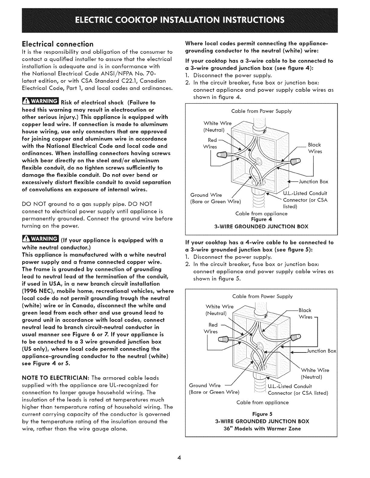
Where local codes permit connecting the appllance-
grounding conductor to the neutral (white) wire:
if your cooktop has a 3-wlre cable to be connected to
a 3-wlre grounded junction box (see figure 4):
1. Disconnect the power supply.
2. In the circuit breaker, fuse box or junction box:
connect appliance and power supply cable wires as
shown in figure 4.
Cable from Power Supply
White Wire ""----_ .....
/Neutral/
i 7{ _+\x
Ground
(Bare or Green Wire)
W I Black
7o n '77F$7°Zj
ii ;-_ _Junction Box
listed)
Cable from appliance
Figure 4
3-WIRE GROUNDED JUNCTION BOX
If your cooklop has a 4-wlre cable to be connected to
a 3-wlre grounded junction box (see figure 5):
1. Disconnect the power supply.
2. In the circuit breaker, fuse box or junction box:
connect appliance and power supply cable wires as
shown in figure 5.
Cable from Power Supply
Whte Wre
Black
(Neutral) _ :::............,_ _"_----_/_---- ....
iI ....:_::_ ), / ---. vvlres
Red :: _ ' /
Wires _'_ __
1
L-J I i t7 . unctionBox
/_:_; .......i ) "White Wire
/ _-ZS. _ (Neutral)
_/ _"--J dmt
Ground Wire L2;;LZ_U.L.-Listed Con "
(Bare or Green Wire) Connector (or CSA listed)
Cable from appliance
Figure 5
3oWIRE GROUNDED JUNCTION BOX
36" Models with Wormer Zone
4
If the appliance is used in a new branch circuit
installatlon (1996 NEC), mobile home, recreational
vehicle, or where local codes DO NOT permit
grounding through the neutral (white) wire, the
appliance frame MUST NOT be connected to the
neutral wire of the 4-wire electrical system.
if your cooktop has a 3=wlre cable (see figure 6):
1. Disconnect the power supply.
2. Separate the green (or bare copper) and white
appliance cable wires.
3. Cap the white wire from the power supply cable if a
3-wire appliance cable is supplied.
4. In the circuit breaker, fuse box or junction box:
connect appliance and power supply cable wires as
shown in figure 6.
Ground Wire
Red
Wires
Cable from Power Supply
.White Wire
Black
Wires
Junction Box
Ground Wire U.L.-Listed Conduit
(Bare or Green Wire) Connector (or CSA
listed)
Cable from appliance
Figure 6
4-WIRE GROUNDED JUNCTION BOX
if your cooktop has a 4 wire cable (see figure 7):
1. Disconnect the power supply.
2. Separate the green (or bare copper) and white
appliance cable wires.
3. In the circuit breaker, fuse box or junction box:
connect appliance and power supply cable wires as
shown in figure 7.
Cable from Power Supply
Ground Wire
Red
White
Wires
-- Black
Ground Wire
(Bare or Green
Wire)
Conduit
Junction Box Connector (or CSA listed)
Cable from appliance
Figure 7
Models 36" with Wormer Zone
4=WIRE GROUNDED JUNCTION BOX
if connecting to a 4=wlre power supply
cable electrlcal system, the appliance frame connected
ground wire MUST NOT be connected to the neutral
wire of the 4=wlre electrlcal system.
5
Cooktop Installation
]. Visually inspect the cooktop for damage. Also make
sure all cool<top screws are tight (see Figure 8).
2. Install the retainer brackets (See Figure 9).
Screws
Figure 8
The retainer brackets MUST be installed, to meet local
codes or, in their absence, with the Natlonal Electrlcal
Code ANSI/NFPA No. 70--latest edition, or with CSA
Standard C22.1, Canadian Electrical Code, Part | (see
Figure 9).
Cooktop Countertop
'Ion
spacer
Retainer bracket
Figure 9
3. Set the cookfop into the countertop cutout.
NOTE: Do not usecauiking compound; cool<top should
be removable for service when needed.
Do not remove the nylon spacers on the
edges of the cooktop. These spacers center the cooktop
in the space provided. The cooktop must be centered
to prevent excess heat buildup that may result in heat
damage or fire (see Figure 10).
2 Nylon
spacers
_JJ__The corners of this unit are fragile.
Carefully install the cooktop by its sides. When
installing, never let the weight of the unit
rest on any one corner.
Checking Operation
Refer to the Use and Care Guide for operation.
Do not touch cooktop glass or elements.
They may be hot enough to burn you.
Model and Serial Number Location
The serial plate is located under the cooktop.
When ordering parts for or making inquiries about your
cookfop, always be sure to include the model and serial
numbers and a lot number or letter from the serial plate
on your cookfop.
Before You Call for Service
Read the Before You Call for Service Checklist and
operating instructions in your Use and Care Guide.
It may save you time and expense. The list includes
common occurrences that are not the result of defective
workmanship or materials in this appliance.
Refer to your Use and Care Guide for Sears service
phone numbers, or caii |=800=4=MY=HOME ®.
6
For typical under counter installation of an electric built-in oven see Figure below.
Only certain cooktop models may be installed
over certain built-in electric oven models.
Approved cooktops and built-in ovens are listed
by the MFG ID number and product code (see the
insert sheet included in the literature package and
cooktop installation instructions for dimensions).
To reduce the risk of
_ersonal injury and
tipping of the wall
oven, the wall oven
mus| be secured to the
cablnet(s) by mounting
brackets.
208/240 Volt junction
box for built-in oven.
Approx. 3'
(Z5cm)
Note 1
i
i
Cut an opening in wood base minimum 4" x 4"
(10.2 X 10.2cm), 2" (5cm) from left side filler
panel, to route armoured cable to junction box.
Note 1: 4" x 4" (10.2cm X 10.2cm) opening to route
armored cable from cooktop to junction box.
Approx. 3", _ 208/240Volt
(7.5cm) _ junction box
for cooktop
Cabinet side fliier panels
are necessary to isolate
the unit from adjoining
cabinets. Cabinet side
filler height should allow
for installation of ap-
proved cooktop models
36" Min.
(91.4cm) Min.
Unit will
overlap
(minimum)
edges by 1"
(2.5cm)
Use 3/4" (1.9cm) plywood,
installed on two runners,
flush with toe plate.
Base must be capable of
supporting 150 pounds
(68kg) for 27" models and
200 pounds (90kg) for
30" models.
If no cooktop is installed
directly over the oven unit,
5" (12.7cm) maximum is
allowed above the floor.
CUTOUT DIMENSIONS
I I
FoWIDTH G. DEPTH H; HEIGHT
27" (68.6cm) 247/8 '' (63.2cm) Min. 27t/4 '' (69.2cm) Min.
Wall Oven 251/4'' (64.1cm) Max. 231/2'' (59.7cm) Min. 28t/4'' (71.8cm) Max.
30" (76.2cm) 281/2'' (72.4cm) Min. 231/2'' (59.7cm) Min. 27t/4 '' (69.2cm) Min.
Wall Oven 29" (73.7cm) Max. 28t/4'' (71.8cm) Max.
Figure 9= TYPICAL UNDER COUNTER INSTALLATION OF A SINGLE ELECTRICBUILT=IN OVEN
WITH AN ELECTRICCOOKTOP MOUNTED ABOVE
7
  • Page 1 1
  • Page 2 2
  • Page 3 3
  • Page 4 4
  • Page 5 5
  • Page 6 6
  • Page 7 7
  • Page 8 8
  • Page 9 9
  • Page 10 10
  • Page 11 11
  • Page 12 12
  • Page 13 13
  • Page 14 14
  • Page 15 15
  • Page 16 16

Kenmore 79041279000 Installation guide

Category
Ovens
Type
Installation guide

Ask a question and I''ll find the answer in the document

Finding information in a document is now easier with AI

in other languages