Dell 567379827 User manual

Category
Notebooks
Type
User manual

This manual is also suitable for

Dell™Latitude™E4200ServiceManual
Notes, Notices, and Cautions
IfyoupurchasedaDELL™nSeriescomputer,anyreferencesinthisdocumenttoMicrosoft
®
Windows
®
operating systems are not applicable.
Information in this document is subject to change without notice.
©2008-2009DellInc.Allrightsreserved.
Reproduction in any manner whatsoever without the written permission of Dell Inc. is strictly forbidden.
Trademarks used in this text: Dell, Latitude, Latitude ON, and the DELL logo are trademarks of Dell Inc.; Bluetooth is a registered trademark owned by Bluetooth SIG, Inc., and is
used by Dell under license; Intel is a registered trademark of Intel Corporation in the U.S. and other countries; Microsoft, Windows, Windows Vista, and the Windows Vista start
button logo are either trademarks or registered trademarks of Microsoft Corporation in the United States and/or other countries.
Other trademarks and trade names may be used in this document to refer to either the entities claiming the marks and names or their products. Dell Inc. disclaims any
proprietary interest in trademarks and trade names other than its own.
October2009Rev.A02
Model PP15S
Troubleshooting
Card With Bluetooth
®
Wireless Technology
Working on Your Computer
Display Assembly
Battery Slice
Camera
Service Panel
Coin-Cell Battery
WLAN/WiMax Card
Palm Rest Assembly
WWAN Card
Fan
LatitudeON™Card
DC Power Cable
Radio Switch Board
System Board Assembly
Solid State Drive
Heatsink Assembly
LED Cover
Smart Card Reader
Keyboard
Speaker
Flashing the BIOS
NOTE: A NOTE indicates important information that helps you make better use of your computer.
NOTICE: A NOTICE indicates either potential damage to hardware or loss of data and tells you how to avoid the problem.
CAUTION: A CAUTION indicates potential for property damage, personal injury, or death.
Back to Contents Page
Battery Slice
Dell™Latitude™E4200ServiceManual
Top View
Bottom View
Setting Up Your Battery Slice
Attaching the Battery Slice to Your Laptop
Detaching the Battery Slice From Your Laptop
Charging Your Battery Slice
Specifications
ThebatterysliceprovidesextendedpoweringcapacitytoyourDell™Latitude™E4200orE4300laptop.
The battery slice attaches to the bottom of the laptop, and can be charged while attached to your laptop or separately.
Top View
Bottom View
Setting Up Your Battery Slice
1
docking connector
2
3
power status light
4
1
charge gauge lights
CAUTION: The AC adapter works with electrical outlets worldwide. However, power connectors and power strips vary among countries. Using an
incompatible cable or improperly connecting the cable to the power strip or electrical outlet may cause fire or equipment damage.
NOTICE: Always use the Dell AC adapter that came with your laptop. If you use any other commercially available AC adapteror the AC adapter
from earlier models of Dell computersyou can damage the battery slice or the laptop.
Connect one end of the AC adapter to the AC adapter connector on your laptop and plug the other end into an electrical outlet.
Attaching the Battery Slice to Your Laptop
1. While holding the laptop at a 30-degree angle to the battery slice, set the slots on the bottom of the laptop onto the battery slice hooks, and then
lower the back of the laptop onto the battery slice. The laptop docking connector should engage the battery slice docking connector.
2. Press the laptop onto the battery slice until you feel a click to indicate that the laptop is firmly seated.
3. Turn on the laptop.
Detaching the Battery Slice From Your Laptop
1. Before you detach the battery slice from your laptop, save and close any open files, and exit any open programs.
2. Set your laptop power management settings so that the laptop does not enter sleep, standby, or hibernate mode when you close (lower) the display:
Microsoft
®
Windows
®
XP
a. Click Start® Control Panel® Performance and Maintenance® Power Options® Advanced.
b. Under When I close the lid of my portable computer, select Do nothing.
Windows Vista
®
a. Click Start ® Control Panel® Mobile PC® Power Options® Change what closing the lid does.
b. Under the When I close the lid drop-down menu, select Do nothing.
c. Pull the laptop release lever to release the laptop from the battery slice.
NOTICE: When you disconnect the Dell AC adapter cable from the laptop, grasp the connector, not the cable itself, and pull firmly but gently to
avoid damaging the cable. When you wrap the AC adapter cable, ensure that you follow the angle of the connector on the AC adapter to avoid
damaging the cable.
NOTE: After attaching the battery slice to your laptop, the laptop AC adapter can charge the battery slice through the laptop AC adapter connector.
1
laptop
2
docking connector
3
battery slice
4
battery slice hooks (2)
4. Lift the back edge of the laptop up and slide the laptop toward the back of the battery slice.
Charging Your Battery Slice
Your battery slice charges whenever it is attached to the laptop and the laptop is attached to an electrical outlet through the AC adapter.
You can also charge your battery slice when it is detached from your laptop using an AC adapter that is compatible with your laptop. Connect an AC adapter to
the AC adapter connector on the battery slice and to an electrical outlet.
Power Status Light
When the battery slice charges, the power status light (see Top View) indicates the following states:
Charge Gauge
The operating time of a battery slice depends on the number of times it is charged. To check the battery charge, press and release the status button on
charge gauge (see Bottom View) to illuminate the charge-level lights. Each light represents approximately 20 percent of total battery charge. For general
battery information, see the Dell Technology Guide at support.dell.com.
Specifications
Latitude E4200 Battery Slice
1
battery slice
2
release lever
Status
Pattern
An unsupported, non-Dell AC adapter is attached to
your laptop.
Alternately blinking amber light and blue light
Temporary battery failure with AC adapter present.
Alternately blinking amber light with steady blue light
Fatal battery failure with AC adapter present.
Constantly blinking amber light
Battery in full charge mode with AC adapter present.
Light off
Battery in charge mode with AC adapter present.
Blue light on
Physical
Height
9.5 mm (0.37 inch)
Width
297 mm (11.69 inches)
Depth
186 mm (7.32 inches)
Weight
614 g (1.35 lb) maximum
AC Adapter
Latitude E4300 Battery Slice
Back to Contents Page
Input voltage
100240 VAC
Input frequency
5060 Hz
Rated output voltage
19.5 VDC
PortsandConnectors
Docking
100-pin connector
Physical
Height
8.9 mm (0.35 inch) to 10.5 mm (0.41 inch)
Width
298.9 mm (11.8 inches)
Depth
200.33 mm (7.9 inches)
Weight
630 g (1.38 lb) maximum
AC Adapter
Input voltage
100240 VAC
Input frequency
5060 Hz
Rated output voltage
19.5 VDC
PortsandConnectors
Docking
100-pin connector
Back to Contents Page
Working on Your Computer
Dell™Latitude™E4200ServiceManual
Recommended Tools
Before Working on Your Computer
After Working on Your Computer
This document provides procedures for removing and installing the components in your computer. Unless otherwise noted, each procedure assumes that:
l You have performed the steps in Before Working on Your Computer.
l You have read the safety information that shipped with your computer.
For additional safety best practices information, see the Regulatory Compliance Homepage on www.dell.com at:
www.dell.com/regulatory_compliance.
Recommended Tools
The procedures in this document may require the following tools:
l Small flat-blade screwdriver
l Phillips screwdriver
l Small plastic scribe
l Flash BIOS update (see the Dell Support website at support.dell.com)
Before Working on Your Computer
Use the following safety guidelines to help protect your computer from potential damage and to help ensure your own personal safety.
1. Ensure that the work surface is flat and clean to prevent the computer cover from being scratched.
2. Shut down your computer.
l In Windows XP, click Start® Shutdown® Shutdown.
l In Windows Vista, click Start , click the arrow icon, and then click Shut Down to turn off your computer.
3. Disconnect your computer and all attached devices from their electrical outlets.
4. Disconnect any network cables from the computer.
NOTE: The color of your computer and certain components may appear differently than shown in this document.
CAUTION: Before working inside your computer, read the safety information that shipped with your computer. For additional safety best
practices information, see the Regulatory Compliance Homepage on www.dell.com at: www.dell.com/regulatory_compliance.
CAUTION: Many repairs may only be done by a certified service technician. You should only perform troubleshooting and simple repairs as
authorized in your product documentation, or as directed by the online or telephone service and support team. Damage due to servicing that is not
authorized by Dell is not covered by your warranty. Read and follow the safety instructions that came with the product.
NOTICE: To avoid electrostatic discharge, ground yourself by using a wrist grounding strap or by periodically touching an unpainted metal
surface, such as a connector on the back of the computer.
NOTICE: Handle components and cards with care. Do not touch the components or contacts on a card. Hold a card by its edges or by its metal
mounting bracket. Hold a component such as a processor by its edges, not by its pins.
NOTICE: When disconnecting a cable, pull on the cable's connector or on its strain-relief loop, not on the cable itself. For cable connectors with
release tabs, pull gently on the release tabs to release the connector. When connecting a cable, ensure that the connectors are correctly oriented
and aligned to avoid damage to the connector and/or the connector's pins.
NOTE: Ensure that the computer is off and not in a power management mode. If you cannot shut down the computer using the operating system,
press and hold the power button for 4 seconds.
NOTICE: To help prevent damage to the system board, you must remove the battery from the battery bay before you service the computer.
5. Disconnect any external devices and remove any installed cards before working on your computer:
l To remove any installed cards, such as an ExpressCard, see the Dell™TechnologyGuide on your computer or at support.dell.com.
l To undock from a docking station, see the E-Port User's Guide or the E-Port Plus User's Guide on support.dell.com.
l To remove a battery slice, see the documentation that shipped with your battery slice or on support.dell.com.
l To remove a media base, see the documentation that shipped with your base or on support.dell.com.
6. Turn the computer upside down.
7. Slide the battery release latches away from each other to lock them in an open position.
8. Slide the battery out of the battery bay.
9. Turn the computer topside up, open the display, and press the power button to ground the system board.
After Working on Your Computer
After you have completed the replacement procedures, ensure you connect the external devices, cards, cables, etc. before turning on your computer.
1. Replace the battery. Slide the battery into the battery bay until it clicks into place.
2. Connect any external devices, such as a docking station, battery slice, or media base, and replace any cards, such as an ExpressCard.
3. Connect any network cables to your computer.
4. Connect your computer and all attached devices to their electrical outlets.
5. Turn on your computer.
Back to Contents Page
1
battery
2
battery release latches (2)
NOTE: To avoid damage to the computer, use only the battery designed for this particular Dell computer. Do not use batteries designed for other Dell
computers.
Back to Contents Page
Flashing the BIOS
Dell™Latitude™E4200ServiceManual
Flashing the BIOS From a CD
Flashing the BIOS From the Hard Drive
Flashing the BIOS From a USB Key
If a BIOS-update program CD is provided with a new system board, flash the BIOS from the CD. If you do not have a BIOS-update program CD, flash the BIOS
from the hard drive.
Flashing the BIOS From a CD
1. Ensure that the AC adapter is plugged in and that the main battery is installed properly.
2. Press <F12> before inserting the BIOS-update program CD so that you can set up the computer to boot from a CD for one time only. Otherwise, you
must enter the system setup program to change the default boot order.
3. Insert the BIOS-update program CD, and turn on the computer.
Follow the instructions that appear on the screen. The computer continues to boot and updates the new BIOS. When the flash update is complete, the
computer will automatically reboot.
4. Remove the flash BIOS update program CD from the drive.
Flashing the BIOS From the Hard Drive
1. Ensure that the AC adapter is plugged in, the main battery is properly installed, and a network cable is attached.
2. Turn on the computer.
3. Locate the latest BIOS update file for your computer at support.dell.com.
4. Click Download Now to download the file.
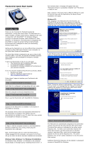
5. If the Export Compliance Disclaimer window appears, click Yes, I Accept this Agreement.
The File Download window appears.
6. Click Save this program to disk, and then click OK.
The Save In window appears.
7. Click the down arrow to view the Save In menu, select Desktop, and then click Save.
The file downloads to your desktop.
8. Click Close if the Download Complete window appears.
NOTICE: If you are replacing the system board, make sure the correct SATA mode is selected in the system setup program. All replacement
system boards for your computer have the SATA operation set to IRRT mode by default. If you have installed or deployed an image in a different
SATA mode (ATA or AHCI), there is a risk of data loss upon boot, which may require you to reinstall the operating system. For more information
onsettingtheSATAmodeinthesystemsetupprogram,seetheDell™TechnologyGuideonyourcomputeroratsupport.dell.com.
NOTE: If you are replacing the system board, the replacement kit for the system board includes media that provides a utility for transferring the Service
Tag to the replacement system board. Make sure that you run this utility before flashing the BIOS.
NOTICE: Plug the AC adapter into a known good power source to prevent a loss of power. Failure to do so may cause damage to your computer.
NOTICE: Do not interrupt this process once it begins. Doing so may cause damage to your computer.
NOTICE: Plug the AC adapter into a known good power source to prevent a loss of power. Failure to do so may cause damage to your computer.
The file icon appears on your desktop and is titled the same as the downloaded BIOS update file.
9. Double-click the file icon on the desktop and follow the instructions on the screen.
Flashing the BIOS From a USB Key
1. Ensure that the AC adapter is plugged in and that the main battery is installed properly.
2. Verify that the USB port is enabled in the system setup program. See the Dell™TechnologyGuide on your computer or at support.dell.com for
information on enabling the USB port.
3. Insert the bootable USB key with the BIOS-update and turn on the computer.
4. Press <F12> so that you can set up the computer to boot from the USB key for one time only. Otherwise, you must enter the system setup program to
change the default boot order, setting USB as the first boot device.
Follow the instructions that appear on the screen. The computer continues to boot and updates the new BIOS. When the flash update is complete, the
computer will automatically reboot.
5. Remove the USB key from the USB port.
Back to Contents Page
NOTICE: Plug the AC adapter into a known good power source to prevent a loss of power. Failure to do so may cause damage to your computer.
NOTICE: Do not interrupt this process once it begins. Doing so may cause damage to your computer.
Back to Contents Page
Card With Bluetooth
®
Wireless Technology
Dell™Latitude™E4200ServiceManual
Removing the Card With Bluetooth Wireless Technology
Replacing the Card With Bluetooth Wireless Technology
Removing the Card With Bluetooth Wireless Technology
1. Follow the procedures in Before Working on Your Computer.
2. Remove the LED cover (see Removing the LED Cover).
3. Remove the keyboard (see Removing the Keyboard).
4. Disconnect the cable from the system board by gently pulling up on the release latch.
5. Lift up on the module to remove it from the base assembly.
6. Turn the module upside down.
7. Remove the M2 x 3-mm screw from the card.
8. Pull up on the card to disconnect it from the connector on the module.
Replacing the Card With Bluetooth Wireless Technology
1. Connect the card to the card connector on the module.
2. Replace the M2 x 3-mm screw on the card.
3. Turn the module topside up, and press the module into the base assembly.
4. Connect the cable to the system board using the release latch.
5. Replace the keyboard (see Replacing the Keyboard).
CAUTION: Before working inside your computer, read the safety information that shipped with your computer. For additional safety best
practices information, see the Regulatory Compliance Homepage on www.dell.com at: www.dell.com/regulatory_compliance.
1
release latch
2
cable
3
base assembly
4
module
5
card
6
card connector
7
screw
6. Replace the LED cover (see Replacing the LED Cover).
7. Follow the procedures in After Working on Your Computer.
Back to Contents Page
Camera
Dell™Latitude™E4200ServiceManual
Removing the Camera
Replacing the Camera
If you ordered a camera with your computer, the camera is already installed.
Removing the Camera
1. Follow the instructions in Before Working on Your Computer.
2. Remove the keyboard (see Removing the Keyboard).
3. Remove the display assembly (see Removing the Display Assembly).
4. Remove the display bezel (see Removing the Display Bezel).
5. Remove the display panel (see Removing the Display Panel).
6. Remove the display hinges (see Removing the Display Hinges).
7. Lift the camera board from the display back cover.
8. Free the display/camera cable assembly from the display hinges.
Replacing the Camera
1. Align the camera board to the alignment posts on the display cover.
2. Re-thread the display cables through the hinges.
3. Replace the display hinges (see Replacing the Display Hinges).
CAUTION: Before working inside the computer, read the safety information that shipped with the computer. For additional safety best practices
information, see the Regulatory Compliance Homepage on www.dell.com at: www.dell.com/regulatory_compliance.
NOTICE: To avoid electrostatic discharge, ground yourself by using a wrist grounding strap or by periodically touching an unpainted metal surface
(such as the back panel) on the computer.
1
alignment post (2)
2
camera board
3
display/camera cable assembly
NOTE: This procedure assumes that you have completed the removal procedure first.
4. Replace the display panel (see Replacing the Display Panel).
5. Replace the display bezel (see Replacing the Display Bezel).
6. Replace the display assembly (see Replacing the Display Assembly).
7. Follow the instructions in After Working on Your Computer.
Back to Contents Page
Coin-Cell Battery
Dell™Latitude™E4200ServiceManual
Removing the Coin-Cell Battery
Replacing the Coin-Cell Battery
Removing the Coin-Cell Battery
1. Follow the procedures in Before Working on Your Computer.
2. Remove the LED cover (see Removing the LED Cover).
3. Remove the keyboard (see Removing the Keyboard).
4. Pry up the coin-cell battery to release the double-sided adhesive tape on the bottom.
5. Lift the coin-cell battery out of the computer.
6. Disconnect the battery cable from the system board.
Replacing the Coin-Cell Battery
1. Connect the coin-cell battery cable to the system board.
2. Insert the coin-cell battery into the computer.
3. If you are re-installing the old coin-cell battery, press down to seal the tape on the bottom.
If you are installing a new coin-cell battery, remove the adhesive backing from the battery and slide the battery under the tab. Press to seal the tape on
the bottom.
CAUTION: Before working inside your computer, read the safety information that shipped with your computer. For additional safety best
practices information, see the Regulatory Compliance Homepage on www.dell.com at: www.dell.com/regulatory_compliance.
1
battery cable
2
LED board cable
3
coin-cell battery
CAUTION: Before working inside your computer, read the safety information that shipped with your computer. For additional safety best
practices information, see the Regulatory Compliance Homepage on www.dell.com at: www.dell.com/regulatory_compliance.
4. Replace the keyboard (see Replacing the Keyboard).
5. Replace the LED cover (see Replacing the LED Cover).
6. Follow the procedures in After Working on Your Computer.
Back to Contents Page
1
battery cable
2
LED board cable
3
coin-cell battery
Back to Contents Page
Display Assembly
Dell™Latitude™E4200ServiceManual
Types of Liquid Crystal Display (LCD) Covers
The five LCD cover designs that can be ordered in different color options are:
l WLAN support only with short antenna cable:
l No bumps
l Short antenna cable (WLAN antenna cables connect to the radio switch board)
l WWAN and WLAN support only:
l A bump on either side of the LCD top cover
l WLAN cables route to the radio switch board
l WWAN cables route to the WWAN card
l WLAN, WWAN, and Camera bump support:
l A bump on either side of the LCD top cover
l WLAN cables route to the radio switch board
l WWAN cables route to the WWAN card
Removing the Display Assembly
1. Follow the instructions in Before Working on Your Computer.
2. Remove the service panel (see Removing the Service Panel).
3. Disconnect the WLAN and WWAN cables.
4. Turn the computer topside up.
5. Remove the LED cover (see Removing the LED Cover).
6. Remove the keyboard (see Removing the Keyboard).
7. Disconnect the cable to the display assembly by gently pulling up on the tab near the cable's connector.
8. Disconnect the antenna cables.
If present, remove the radio switch board (see Removing the Radio Switch Board) and disconnect and unroute the WWAN cables.
If the radio switch board is not present, disconnect and unroute the WLAN and WWAN cables.
9. Position all cables leading to the display assembly to the rear of the computer.
10. Remove the four M2.5 x 5-mm screws securing the display assembly.
Types of Liquid Crystal Display (LCD) Covers
Removing the Display Assembly
Replacing the Display Assembly
Removing the Display Bezel
Replacing the Display Bezel
Removing the Display Panel
Replacing the Display Panel
Removing the Display Hinges
Replacing the Display Hinges
Removing the Display Cable/Display Cable with Camera
Replacing the Display Cable/Display cable with Camera
CAUTION: Before working inside your computer, read the safety information that shipped with your computer. For additional safety best
practices information, see the Regulatory Compliance Homepage on www.dell.com at: www.dell.com/regulatory_compliance.
11. Open the display to 90 degrees and lift the display assembly off the base assembly.
Replacing the Display Assembly
1. Align the display hinges with the holes in the base of the computer, and lower the display into place.
2. Route the display cable under each tab in its routing channel, and connect the cable to the display cable connector on the system board.
3. Route the wireless (WLAN and WWAN) cables and radio switch board cables (if applicable) under each tab in the routing channel and then under the
right I/O board ribbon cable.
4. Close the display and turn the computer upside down.
5. Replace the four M2.5 x 5-mm screws to secure the display assembly.
6. Depending on the cards in your computer configuration, connect the antenna cables to their respective cards:
For WWAN, see Replacing a WWAN Card.
For radio switch board, see Replacing the Radio Switch Board.
1
screws (4)
1
display assembly
2
display cable
3
base assembly
4
wireless cables
CAUTION: Before working inside your computer, read the safety information that shipped with your computer. For additional safety best
practices information, see the Regulatory Compliance Homepage on www.dell.com at: www.dell.com/regulatory_compliance.
For WLAN, see Replacing the WLAN/WiMax Card.
7. Place any unused antenna cables in the base assembly cable holders next to the card slot.
8. Replace the keyboard (see Replacing the Keyboard).
9. Replace the LED cover (see Replacing the LED Cover).
10. Replace the service panel (see Replacing the Service Panel).
11. Follow the procedures in After Working on Your Computer.
Removing the Display Bezel
1. Follow the instructions in Before Working on Your Computer.
2. Remove the service panel (see Removing the Service Panel).
3. Remove the LED cover (see Removing the LED Cover).
4. Remove the keyboard (see Removing the Keyboard).
5. Remove the display assembly (see Removing the Display Assembly).
6. Starting from one side of the bezel, use your fingers to pry the inside edges of the bezel upward and outward from the display panel. Lift up on the
released side of the bezel, and continue to release the top and bottom of the bezel. Release the remaining side of the bezel last.
7. Once all snaps are released, lift the bezel from the display assembly.
Replacing the Display Bezel
CAUTION: Before working inside your computer, read the safety information that shipped with your computer. For additional safety best
practices information, see the Regulatory Compliance Homepage on www.dell.com at: www.dell.com/regulatory_compliance.
NOTICE: Removal of the bezel from the display back cover requires extreme care to avoid damage to the bezel and the display panel. Special
attention is required for the corners, especially for the bezels used with the LED display panels.
NOTICE: To avoid permanent damage to the display panel, do not press or rub on the center of the panel.
1
left side of display bezel
2
top of display bezel
3
right side of display bezel
4
snaps
5
bottom of display bezel
6
display assembly
CAUTION: Before working inside your computer, read the safety information that shipped with your computer. For additional safety best
practices information, see the Regulatory Compliance Homepage on www.dell.com at: www.dell.com/regulatory_compliance.
1. Align the bezel edges with those on the display assembly, and gently snap the bezel into place around the entire perimeter of the assembly.
2. Replace the display assembly (see Replacing the Display Assembly).
3. Replace the keyboard (see Replacing the Keyboard).
4. Replace the LED cover (see Replacing the LED Cover).
5. Replace the service panel (see Replacing the Service Panel).
6. Follow the procedures in After Working on Your Computer.
Removing the Display Panel
1. Follow the instructions in Before Working on Your Computer.
2. Remove the service panel (see Removing the Service Panel).
3. Remove the LED cover (see Removing the LED Cover).
4. Remove the keyboard (see Removing the Keyboard).
5. Remove the display assembly (see Removing the Display Assembly).
6. Remove the display bezel (see Removing the Display Bezel).
7. Remove the four M2 x 3-mm screws from the display panel.
NOTICE: To avoid permanent damage to the display panel, do not press or rub on the center of the panel.
NOTICE: When replacing the display bezel, press only on the outer edges when snapping the bezel into place. Pressing on the inner edges could
cause the display panel to crack.
1
display bezel
2
display assembly
CAUTION: Before working inside your computer, read the safety information that shipped with your computer. For additional safety best
practices information, see the Regulatory Compliance Homepage on www.dell.com at: www.dell.com/regulatory_compliance.
CAUTION: The tabs on the outer edges of the display panel are made of very thin metal, and could cut the skin if not handled with care.
NOTICE: To avoid permanent damage to the display panel, do not press or rub on the center of the panel.
NOTICE: To avoid permanent damage to the display panel, lift the panel using both hands on the sides of the panel.
8. Lift the display panel out of the display cover and carefully lay the display panel flat on your workspace on a clean and soft type of material. Be careful to
avoid damaging the display panel with the hinges and cables on the display cover.
9. Disconnect the display cable.
Peel back the adhesive tape, then pull the cable out of the connector.
Replacing the Display Panel
1. Place the display panel upside down on your workspace in front of the display cover.
1
screws (4)
2
display panel
3
display cover
NOTICE: Failure to peel back the adhesive tape prior to disconnecting the display cable can cause permanent damage to the cable.
NOTICE: To avoid permanent damage to the display cable and the display panel, pull evenly on the left and right sides of the cable connector
when removing the cable.
1
underside of display panel
2
display cable
3
adhesive tape
4
display cable connector
CAUTION: Before working inside your computer, read the safety information that shipped with your computer. For additional safety best
practices information, see the Regulatory Compliance Homepage on www.dell.com at: www.dell.com/regulatory_compliance.
CAUTION: The tabs on the outer edges of the display panel are made of very thin metal, and could cut the skin if not handled with care.
NOTICE: To avoid permanent damage to the display panel, do not press or rub on the center of the panel.
NOTICE: To avoid permanent damage to the display panel, lift the panel using both hands on the sides of the panel.
NOTICE: To avoid permanent damage to the display panel when connecting the display cable, insert the cable into the display panel connector by
evenly pushing the left and right edges of the cable connector. Do not grip or hold the display panel by the circuit board on the bottom edge of the
panel.
  • Page 1 1
  • Page 2 2
  • Page 3 3
  • Page 4 4
  • Page 5 5
  • Page 6 6
  • Page 7 7
  • Page 8 8
  • Page 9 9
  • Page 10 10
  • Page 11 11
  • Page 12 12
  • Page 13 13
  • Page 14 14
  • Page 15 15
  • Page 16 16
  • Page 17 17
  • Page 18 18
  • Page 19 19
  • Page 20 20
  • Page 21 21
  • Page 22 22
  • Page 23 23
  • Page 24 24
  • Page 25 25
  • Page 26 26
  • Page 27 27
  • Page 28 28
  • Page 29 29
  • Page 30 30
  • Page 31 31
  • Page 32 32
  • Page 33 33
  • Page 34 34
  • Page 35 35
  • Page 36 36
  • Page 37 37
  • Page 38 38
  • Page 39 39
  • Page 40 40
  • Page 41 41
  • Page 42 42
  • Page 43 43
  • Page 44 44
  • Page 45 45
  • Page 46 46
  • Page 47 47
  • Page 48 48
  • Page 49 49
  • Page 50 50
  • Page 51 51
  • Page 52 52
  • Page 53 53
  • Page 54 54
  • Page 55 55
  • Page 56 56
  • Page 57 57
  • Page 58 58
  • Page 59 59
  • Page 60 60
  • Page 61 61
  • Page 62 62
  • Page 63 63
  • Page 64 64
  • Page 65 65
  • Page 66 66
  • Page 67 67
  • Page 68 68
  • Page 69 69
  • Page 70 70
  • Page 71 71
  • Page 72 72
  • Page 73 73

Dell 567379827 User manual

Category
Notebooks
Type
User manual
This manual is also suitable for

Ask a question and I''ll find the answer in the document

Finding information in a document is now easier with AI