HP Cell Phone Accessories 8935 User manual
- Category
- Measuring, testing & control
- Type
- User manual
This manual is also suitable for

HP 8935 CDMA Cellular/PCS Base Station
Test Set
AMPS Base Station Tests
Application Guide
Firmware Version: A.01.00 and above
HP Part Number: E6380-90017
Revision A
Printed in U.S.A
November 1997
© Copyright Hewlett-Packard Company 1997
Main Menu

2
Notice
Information contained in this document is subject to change without
notice.
All Rights Reserved. Reproduction, adaptation, or translation without
prior written permission is prohibited, except as allowed under the
copyright laws.
This material may be reproduced by the U.S. Government pursuant to
the Copyright License under the clause at DFARS 52.227-7013 (APR
1998).
Main Menu

3
Manufacturer’s Declaration
This statement is provided to comply with the requirements of the
German Sound Emission Directive, from 18 January 1991.
This product has a sound pressure emission (at the operator position)
< 70 dB(A).
Sound Pressure Lp < 70 dB(A)
At Operator Position
Normal Operation
According to ISO 7779:1988/EN 27779:1991 (Type Test).
Herstellerbescheinigung
Diese Information steht im Zusammenhang mit den Anforderungen der
Maschinenlärminformationsverordnung vom 18 January 1991.
Schalldruckpegel Lp < 70 dB(A).
Am Arbeitsplatz
Normaler Betrieb.
Nach ISO 7779:1988/EN 27779:1991 (Typprüfung).
Main Menu

4
Safety
GENERAL
This product and related documentation must be reviewed for
familiarization with safety markings and instructions before operation.
This product has been designed and tested in accordance with IEC
Publication 1010, "Safety Requirements for Electronic Measuring
Apparatus," and has been supplied in a safe condition. This instruction
documentation contains information and warnings which must be
followed by the user to ensure safe operation and to maintain the
product in a safe condition.
SAFETY SYMBOLS
Indicates instrument damage can occur if indicated operating limits are
exceeded. Refer to the instructions in this guide.
Indicates hazardous voltages.
Indicates earth (ground) terminal
WARNING A WARNING note denotes a hazard. It calls attention to a
procedure, practice, or the like, which, if not correctly
performed or adhered to, could result in personal injury. Do not
proceed beyond a WARNING sign until the indicated conditions
are fully understood and met.
CAUTION A CAUTION note denotes a hazard. It calls attention to an operation
procedure, practice, or the like, which, if not correctly performed or
adhered to, could result in damage to or destruction of part or all of the
product. Do not proceed beyond an CAUTION note until the indicated
conditions are fully understood and met.
Safety Considerations for this Instrument
!
Main Menu

5
WARNING This product is a Safety Class I instrument (provided with a
protective earthing ground incorporated in the power cord).
The mains plug shall only be inserted in a socket outlet
provided with a protective earth contact. Any interruption of
the protective conductor inside or outside of the product is
likely to make the product dangerous. Intentional interruption
is prohibited.
Do not expose to or operate this instrument in outdoor
atmospheric conditions such as direct rain, hail, sleet, snow,
icing, sunshine or wind. Operate this instrument only within its
specified temperature humidity conditions.
This instrument is equipped with internal ground fault circuit
interrupter class A.
• This device does not protect against electrical shock due to
contact with both circuit conductors or a fault in supply
wiring to product.
• Do not use extension cord to connect this product to power
receptacle. Attention-ne pas utiliser de rallonge pour
raccorder le detecteur-disjoncteur a la prise de courant.
• Replace cordset only with HP 8120 series. Attention -
Remplacer uniquement par un cordon amovible numero
8120.
• Do not use in wet location. Ne pas utiliser dans un
emplacement mouille.
WARNING Whenever it is likely that the protection has been impaired, the
instrument must be made inoperative and be secured against
any unintended operation.
If this instrument is to be energized via an autotransformer (for
voltage reduction), make sure the common terminal is
connected to the earth terminal of the power source.
If this product is not used as specified, the protection provided
by the equipment could be impaired. This product must be used
in a normal condition (in which all means for protection are
intact) only.
No operator serviceable parts in this product. Refer servicing to
qualified personnel. To prevent electrical shock, do not remove
covers.
Servicing instructions are for use by qualified personnel only.
To avoid electrical shock, do not perform any servicing unless
you are qualified to do so.
!
!
!
Main Menu

6
The opening of covers or removal of parts is likely to expose
dangerous voltages. Disconnect the product from all voltage
sources while it is being opened.
Adjustments described in the manual are performed with
power supplied to the instrument while protective covers are
removed. Energy available at many points may, if contacted,
result in personal injury.
The power cord is connected to internal capacitors that my
remain live for 5 seconds after disconnecting the plug from its
power supply.
For Continued protection against fire hazard, replace the line
fuse(s) only with 250 V fuse(s) or the same current rating and
type (for example, normal blow or time delay). Do not use
repaired fuses or short circuited fuseholders. FUSE: T 5.0A
CAUTION Always use the three-prong ac power cord supplied with this product.
Failure to ensure adequate earth grounding by not using this cord may
cause personal injury and/or product damage.
This product is designed for use in Installation Category II and
Pollution Degree 2 per IEC 1010 and IEC 664 respectively. For indoor
use only.
This product has autoranging line voltage input, be sure the supply
voltage is within the specified range.
Ventilation Requirements: When installing the product in a cabinet,
the convection into and out of the product must not be restricted. The
ambient temperature (outside the cabinet) must be less than the
maximum operating temperature of the product by 4° C for every 100
watts dissipated in the cabinet. If the total power dissipated in the
cabinet is greater than 800 watts, then forced convection must be used.
To prevent electrical shock, disconnect instrument from mains (line)
before cleaning. Use a dry cloth or one slightly dampened with water to
clean the external case parts. Do not attempt to clean internally.
Main Menu

7
Product Markings
CE - the CE mark is a registered trademark of the European
Community. A CE mark accompanied by a year indicated the year the
design was proven.
CSA - the CSA mark is a registered trademark of the Canadian
Standards Association.
CERTIFICATION
Hewlett-Packard Company certifies that this product met its published
specifications at the time of shipment from the factory.
Hewlett-Packard further certifies that its calibration measurements
are traceable to the United States National Institute of Standards and
Technology, to the extent allowed by the Institute’s calibration facility,
and to the calibration facilities of other International Standards
Organization members.
Main Menu

8
Warranty
This Hewlett-Packard instrument product is warranted against defects
in material and workmanship for a period of one year from date of
shipment. During the warranty period, Hewlett-Packard Company will
at its option, either repair or replace products which prove to be
defective.
For warranty service or repair, this product must be returned to a
service facility designated by HP. Buyer shall prepay shipping charges
to HP and HP shall pay shipping charges, duties, and taxes for products
returned to HP from another country.
HP warrants that its software and firmware designated by HP for use
with an instrument will execute its programming instructions when
properly installed on that instrument. HP does not warrant that the
operation of the instrument, or software, or firmware will be
uninterrupted or error free.
LIMITATION OF WARRANTY
The foregoing warranty shall not apply to defects resulting from
improper or inadequate maintenance by Buyer, Buyer-supplied
software or interfacing, unauthorized modification or misuse, operation
outside of the environmental specifications for the product, or improper
site preparation or maintenance.
NO OTHER WARRANTY IS EXPRESSED OR IMPLIED. HP
SPECIFICALLY DISCLAIMS THE IMPLIED WARRANTIES OF
MERCHANTABILITY AND FITNESS FOR A PARTICULAR
PURPOSE.
EXCLUSIVE REMEDIES
THE REMEDIES PROVIDED HEREIN ARE BUYER’S SOLE AND
EXCLUSIVE REMEDIES. HP SHALL NOT BE LIABLE FOR ANY
DIRECT, INDIRECT, SPECIAL, INCIDENTAL, OR
CONSEQUENTIAL DAMAGES, WHETHER BASE ON CONTRACT,
TORT, OR ANY OTHER LEGAL THEORY.
Main Menu

9
ASSISTANCE
Maintenance Agreements
Product maintenance agreements and other customer assistance
agreements are available for Hewlett-Packard products. For any
assistance, contact your nearest Hewlett-Packard Sales and Service
Office.
Main Menu

10
Regional Sales Offices
IMPORTANT Regional Sales and Service Offices
Eastern USA
Sales Office
Hewlett-Packard Company
2101 Gather Rd.
Rockville, MD 20850
Tel: (301) 258-2000
Eastern USA
Sales Office
Hewlett-Packard Company
2101 Gather Rd.
Rockville, MD 20850
Tel: (301) 258-2000
Midwestern USA
Sales and Service
Hewlett-Packard Company
5201 Tollview Drive
Rolling Meadows, IL 60008
Tel: (708) 342-2000
Southern USA
Sales and Service
Hewlett-Packard Company
1995 North Park Place
Atlanta, GA 30339
Sales
Tel: (404) 955-1500
Fax: (404) 980-7292
Service
Tel: (404) 850-2544
Fax: (404) 980-7292
Southern USA
Service Center
Hewlett-Packard Company
930 E. Campbell Road
Richardson, TX 75081
Tel: (214) 699-4331
Western USA
Service Center
Hewlett-Packard Company
301 E. Evelyn Avenue
Mountain View, CA 94041
Tel: (415) 694-2000
Fax: (415) 694-0601
Western USA
Sales and Service
Hewlett-Packard Company
24 Inverness Place East
Englewood, CO 80112
Sales
Tel: (303) 649-5000
Fax: (303) 649-5787
Service
Tel: (303) 649-5512
Fax: (303) 649-5787
Western USA
Sales and Service
Hewlett-Packard Company
1421 South Manhattan Avenue
Fullerton, CA 92631
Sales
Tel: (714) 999-6700
Fax: (714) 778-3033
Service
Tel: (714) 758-5490
Fax: (714) 778-3033
United States of America
Customer Information Center
Hewlett-Packard Company
Tel: (800) 752-0900
6:00 am to 5:00 pm Pacific Time
Parts Direct: 1-800-227-8164
South Eastern Europe
Sales and Service
Hewlett-Packard Ges. m.b.h.
Liebigasse 1
P.O. Box 72
A-1222 Vienna, Austria
Telephone: 43 222 2500 0
Telex: 13 4425
European Multicountry Region
Sales and Service
Hewlett-Packard S.A.
P.O. Box 95
150, Route dv Nant_dl_AVRIL
CH-1217 Meyrin 2
Geneva, Switzerland
Telephone: (41/22) 780-8111
Fax: (41/22) 780-8542
Northern Europe
Sales and Service
Hewlett-Packard Nederland B.V.
Startbaan 16
1187 XR
Amstelveen, The Netherlands
P.O. Box 667
Telephone: 31/20 5476911 X 6631
Fax: 31-20-6471825NL
Main Menu

11
Asia
Sales and Service
Hewlett-Packard Asia Ltd.
22-30/F Peregrine Tower
Lippo Center
89 Queensway, Central
Hong Kong
G.P.O. Box 863 Hong Kong
Telephone: 852-848-7777
Fax: 852-868-4997
Japan
Sales and Service
Yokogawa-Hewlett-Packard Ltd.
3-29-21, Takaido-Higashi
Suginami-Ku, Tokyo 168
Telephone: 81 3 3331-6111
Fax: 81 3 3331-6631
International Sales Branch
Headquarters
Sales and Service
Hewlett-Packard S.A.
39 Rue Veyrot
P.O. Box 365
1217 Meyrin 1
Geneva, Switzerland
Telephone: 41-22-780-4111
Fax: 41-22-780-4770
Australia, New Zealand
Sales and Service
Hewlett-Packard Ltd.
P.O. Box 221
31-41 Joseph Street
Blackburn, Victoria 3130
Telephone: (61/3) 895-2895
Fax: (61/3) 898-9257
Canada
Sales and Service
Hewlett-Packard (Canada) Ltd.
5150 Spectrum Way
Mississauga, Ontario L4W 5G1
Canada
Telephone: (416) 206-4725
Fax: (416) 206-4739
Canada
Service Center
Hewlett-Packard Company
17500 Transcanada Highway
S. Serv Road
Kirkland, Quebec H9J 2X8
Canada
Telephone: (416) 206-3295
Canada
Service Center
Hewlett-Packard Ltd.
11120 178 Street
Edmonton, Alberta T5S 1P2
Canada
Telephone: (403) 486-6666
Fax: (403) 489-8764
Latin America
Hewlett-Packard Company
LAHQ Mexico City
Col. Lomas de Virreyes
11000 Mexico D.F.
Mexico
Telephone: (52/5) 326-4000
Fax: (52/5) 202 7718
United Kingdom
Sales and Service
Hewlett-Packard Ltd.
Cain Road
Amen Corner
Bracknell, Berkshire
RG12 1HN
United Kingdom
Telephone: 44 344 360000
Main Menu

12
Main Menu

Contents
13
Table of Contents
In This Manual . . . . . . . . . . . . . . . . . . . . . . . . . . . . . . . . . . . . . . . . . . . . 15
1. Getting Started with AMPS Test
About the Test Set. . . . . . . . . . . . . . . . . . . . . . . . . . . . . . . . . . . . . . . . . 18
Product Description . . . . . . . . . . . . . . . . . . . . . . . . . . . . . . . . . . . . . . 18
Batteries . . . . . . . . . . . . . . . . . . . . . . . . . . . . . . . . . . . . . . . . . . . . . . . 18
Getting Help . . . . . . . . . . . . . . . . . . . . . . . . . . . . . . . . . . . . . . . . . . . . 19
What’s Included with this Test Set . . . . . . . . . . . . . . . . . . . . . . . . . . 20
Manual and Automatic Operation Modes . . . . . . . . . . . . . . . . . . . . . . 21
IBASIC programs . . . . . . . . . . . . . . . . . . . . . . . . . . . . . . . . . . . . . . . . 21
Maximizing the Accuracy of Your Measurements. . . . . . . . . . . . . . . . 22
Calibration . . . . . . . . . . . . . . . . . . . . . . . . . . . . . . . . . . . . . . . . . . . . . 22
TX Power Temperature Compensation. . . . . . . . . . . . . . . . . . . . . . . 22
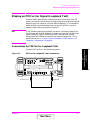
Display an FM Carrier Signal (Loopback Test). . . . . . . . . . . . . . . . . . 23
Connections for FM Carrier Loopback Test . . . . . . . . . . . . . . . . . . . 23
Get Started with the Test Set . . . . . . . . . . . . . . . . . . . . . . . . . . . . . . 24
Preparing the Test Set . . . . . . . . . . . . . . . . . . . . . . . . . . . . . . . . . . . . 24
Generate an FM Carrier Signal. . . . . . . . . . . . . . . . . . . . . . . . . . . . . 24
Analyzing an FM Carrier Signal. . . . . . . . . . . . . . . . . . . . . . . . . . . . 26
What to Do Next. . . . . . . . . . . . . . . . . . . . . . . . . . . . . . . . . . . . . . . . . 27
2. Testing AMPS Base Stations
AMPS Tests You Can Perform . . . . . . . . . . . . . . . . . . . . . . . . . . . . . . . 30
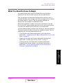
What You Need to Know to Begin . . . . . . . . . . . . . . . . . . . . . . . . . . . . 31
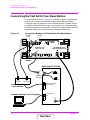
Connecting the Test Set to Your Base Station. . . . . . . . . . . . . . . . . . . 32
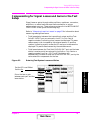
Compensating for Signal Losses and Gains in the Test Setup . . . . . . 33
Transmitter Frequency Error/Offset and Power Test. . . . . . . . . . . . . 34
Prerequisites. . . . . . . . . . . . . . . . . . . . . . . . . . . . . . . . . . . . . . . . . . . . 34
Begin Testing . . . . . . . . . . . . . . . . . . . . . . . . . . . . . . . . . . . . . . . . . . . 34
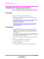
Transmitter SAT Frequency and Deviation. . . . . . . . . . . . . . . . . . . . . 36
Prerequisites. . . . . . . . . . . . . . . . . . . . . . . . . . . . . . . . . . . . . . . . . . . . 36
Test Procedure . . . . . . . . . . . . . . . . . . . . . . . . . . . . . . . . . . . . . . . . . . 36
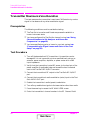
Transmitter Data Deviation . . . . . . . . . . . . . . . . . . . . . . . . . . . . . . . . . 38
Prerequisites. . . . . . . . . . . . . . . . . . . . . . . . . . . . . . . . . . . . . . . . . . . . 38
Test Procedure . . . . . . . . . . . . . . . . . . . . . . . . . . . . . . . . . . . . . . . . . . 38
Transmitter Maximum Voice Deviation. . . . . . . . . . . . . . . . . . . . . . . . 40
Prerequisites. . . . . . . . . . . . . . . . . . . . . . . . . . . . . . . . . . . . . . . . . . . . 40
Test Procedure . . . . . . . . . . . . . . . . . . . . . . . . . . . . . . . . . . . . . . . . . . 40
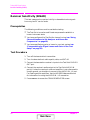
Receiver Sensitivity (SINAD) . . . . . . . . . . . . . . . . . . . . . . . . . . . . . . . . 42
Prerequisites. . . . . . . . . . . . . . . . . . . . . . . . . . . . . . . . . . . . . . . . . . . . 42
Test Procedure . . . . . . . . . . . . . . . . . . . . . . . . . . . . . . . . . . . . . . . . . . 42
Receiver Squelch Threshold . . . . . . . . . . . . . . . . . . . . . . . . . . . . . . . . . 45
Prerequisites. . . . . . . . . . . . . . . . . . . . . . . . . . . . . . . . . . . . . . . . . . . . 45
Test Procedure . . . . . . . . . . . . . . . . . . . . . . . . . . . . . . . . . . . . . . . . . . 45
3. Utility Procedures
Beeper. . . . . . . . . . . . . . . . . . . . . . . . . . . . . . . . . . . . . . . . . . . . . . . . . . . 50
Beeper Control . . . . . . . . . . . . . . . . . . . . . . . . . . . . . . . . . . . . . . . . . . 50
Table of Contents
Main Menu

14
Contents
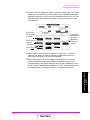
Measuring Insertion Losses . . . . . . . . . . . . . . . . . . . . . . . . . . . . . . . . . 51
Memory Cards . . . . . . . . . . . . . . . . . . . . . . . . . . . . . . . . . . . . . . . . . . . . 52
Memory Cards and Intialization . . . . . . . . . . . . . . . . . . . . . . . . . . . . 52
Oscilloscope . . . . . . . . . . . . . . . . . . . . . . . . . . . . . . . . . . . . . . . . . . . . . . 53
Selecting the Oscilloscope’s Input . . . . . . . . . . . . . . . . . . . . . . . . . . . 54
Selecting the Oscilloscope’s Filters . . . . . . . . . . . . . . . . . . . . . . . . . . 54
Triggering the Oscilloscope . . . . . . . . . . . . . . . . . . . . . . . . . . . . . . . . 55
Using the Marker . . . . . . . . . . . . . . . . . . . . . . . . . . . . . . . . . . . . . . . . 56
Online Help . . . . . . . . . . . . . . . . . . . . . . . . . . . . . . . . . . . . . . . . . . . . . . 57
Help Screen Display. . . . . . . . . . . . . . . . . . . . . . . . . . . . . . . . . . . . . . 57
Ports: HP-IB, Serial and Parallel . . . . . . . . . . . . . . . . . . . . . . . . . . . . . 58
HP-IB Port . . . . . . . . . . . . . . . . . . . . . . . . . . . . . . . . . . . . . . . . . . . . . 58
Serial Ports . . . . . . . . . . . . . . . . . . . . . . . . . . . . . . . . . . . . . . . . . . . . . 58
Parallel Ports . . . . . . . . . . . . . . . . . . . . . . . . . . . . . . . . . . . . . . . . . . . 60
Printing . . . . . . . . . . . . . . . . . . . . . . . . . . . . . . . . . . . . . . . . . . . . . . . . . 61
Configuring the Test Set for Printing . . . . . . . . . . . . . . . . . . . . . . . . 61
Printing a Screen . . . . . . . . . . . . . . . . . . . . . . . . . . . . . . . . . . . . . . . . 61
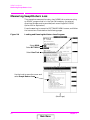
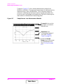
Measuring Swept Return Loss . . . . . . . . . . . . . . . . . . . . . . . . . . . . . . . 62
Tracking Generator . . . . . . . . . . . . . . . . . . . . . . . . . . . . . . . . . . . . . . . . 65
Using the Tracking Generator. . . . . . . . . . . . . . . . . . . . . . . . . . . . . . 65
User Keys. . . . . . . . . . . . . . . . . . . . . . . . . . . . . . . . . . . . . . . . . . . . . . . . 66
Displaying the Pre-assigned Local User Keys . . . . . . . . . . . . . . . . . 66
Assigning a Local User Key. . . . . . . . . . . . . . . . . . . . . . . . . . . . . . . . 66
Assigning a Global User Key. . . . . . . . . . . . . . . . . . . . . . . . . . . . . . . 67
To Release a User Key Assignment. . . . . . . . . . . . . . . . . . . . . . . . . . 67
Using Channel Numbers to Set Analyzer and Generator Frequencies68
RF Chan and Tune Freq Fields . . . . . . . . . . . . . . . . . . . . . . . . . . . . . 69
Voltmeter . . . . . . . . . . . . . . . . . . . . . . . . . . . . . . . . . . . . . . . . . . . . . . . . 70
Measuring AC Level and DC Level. . . . . . . . . . . . . . . . . . . . . . . . . . 70
Main Menu

15
In This Manual
In This Manual
What is Discussed This Manual
This manual explains how to use the HP 8935 to manually test an
AMPS base station.
This document presents a step-by-step approach to AMPS base station
testing using the Test Set, including what you need to know before you
can start testing.
What is Not Discussed in this Manual
• General operation of the Test Set.
Changing display screens and their associated controls is discussed
in the Reference Guide (HP part number E6380-90019).
• Detailed operation of the Test Set’s spectrum analyzer and
oscilloscope.
Although there are basic explanations in this manual, more detail is
provided in the Reference Guide concerning the various control
menus and fields available.
• How to control your base station, switch system, or any other
software or hardware associated with your cell site equipment.
Each manufacturer and cellular service provider has their own cell
site control and base station configuration procedures that go beyond
the scope of this documentation.
• How to perform IBASIC programming operations, such as writing,
editing, copying, or cataloguing programs.
Programming the Test Set is explained in the Programming Manual
(HP part number E6380-90018), and the IBASIC language is
explained in the HP Instrument BASIC User’s Handbook (HP part
number E2083-90005).
Conventions Used in This Manual
The following conventions are used throughout this manual to help
clarify instructions and reduce unnecessary text:
Test Set refers to the HP 8935.
Test Set keys are indicated like this:
Preset
Test Set screen information, such as a measurement result or an error
message, is shown like this: TX Power 7.21 W
In This Manual
Main Menu

16
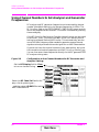
Which Document is
Required?
The following documents are part of the HP 8935 document set. Use the
table to help you decide which document you need.
Table 1 Document Navigation
Document Part Number Usage
CDMA Application
Guide
E6380-90016 Use this manual for basic CDMA measurements
and for getting started with the Test Set.
AMPS Application Guide E6380-90017 Use this manual for making AMPS base station
measurements.
Reference Guide E6380-90019 Use this manual for screen and field descriptions
and general operation information about the Test
Set.
Programmer’s Guide E6380-90018 Use this manual to learn HP-IB syntax and for
learning how to program the Test Set.
Assembly Level Repair
Guide
E6380-90015 Use this manual to perform calibration on the
Test Set and for general service information.
Main Menu

17
1 Getting Started with AMPS Test
This chapter introduces you to the HP 8935 CDMA Cellular/PCS Base
Station Test Set and its AMPS functions. For information on other
functions in the Test Set, see “Which Document is Required?” on page
18. To proceed immediately to the test procedures, see “AMPS Tests
You Can Perform” on page 30.
Chapter 1
Getting Started with AMPS
Test
Main Menu

18 Chapter 1
Getting Started with AMPS Test
About the Test Set
About the Test Set
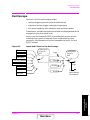
Product Description
This Test Set helps you install, commission, and maintain AMPS base
stations. It also allows you to test CDMA base stations. (This guide
discusses AMPS testing. For more information about CDMA testing,
refer to the CDMA Base Station Tests Applications Guide.)
The Test Set contains an RF signal generator, RF analyzer, AF
analyzer, and AF generator to test AMPS base stations. The following
tools are also included:
Code Domain Analyzer
CDMA Analyzer
CDMA Generator
Spectrum Analyzer
Power Meter
Oscilloscope
AC/DC Voltmeter
IBASIC controller
Batteries
There are two methods the Test Set uses to back up its RAM. One is a
set of two AA batteries mounted inside the rear panel of the Test Set.
You must periodically change these batteries. The second method of
RAM backup is an internal battery. It is not user serviceable.
Failure to take prompt action may result in loss of RAM data including
IBASIC programs and SAVE/RECALL states stored in the RAM.
To change the AA batteries, use the following procedure:
1. Turn off power and unplug the Test Set.
2. Remove the six screws in the rear panel using a TX-15 TORX
(R)
screwdriver.
3. Remove the rear cover.
4. Replace the AA batteries. Do not use rechargeable batteries.
5. Replace the rear panel.
Main Menu

Chapter 1 19
Getting Started with AMPS Test
About the Test Set
Chapter 1
Getting Started with AMPS
Test
Getting Help
If you have problems using this Test Set, and cannot find the solution in
these documents or the help screens, please use one of the following
contacts:
Your local or regional sales office (see "Regional Sales and Service
Offices" on page 12)
U.S. Call Center: 800 542-4844
Korea HP Direct: (82/2) 769-0800
Canada HP Direct: (800) 387-3154
European Call center: +31 20 547-9990
Test and Measurement Organization on the web:
http://www.tmo.hp.com/
Main Menu

20 Chapter 1
Getting Started with AMPS Test
About the Test Set
What’s Included with this Test Set
The equipment commonly shipped with the base Test Set is listed
below. Options that you order with your Test Set may change this list.
Test Set
Documentation:
• CDMA Applications Guide
• CD-ROM with the above listed manual, AMPS Base Station Tests
Applications Guide, Assembly Level Repair Manual,
Programmer’s Guide, and HP 8935 Reference Guide in Adobe™
Acrobat Reader format (.pdf).
Power cord
Cover for the front panel of the Test Set
Main Menu
Page is loading ...
Page is loading ...
Page is loading ...
Page is loading ...
Page is loading ...
Page is loading ...
Page is loading ...
Page is loading ...
Page is loading ...
Page is loading ...
Page is loading ...
Page is loading ...
Page is loading ...
Page is loading ...
Page is loading ...
Page is loading ...
Page is loading ...
Page is loading ...
Page is loading ...
Page is loading ...
Page is loading ...
Page is loading ...
Page is loading ...
Page is loading ...
Page is loading ...
Page is loading ...
Page is loading ...
Page is loading ...
Page is loading ...
Page is loading ...
Page is loading ...
Page is loading ...
Page is loading ...
Page is loading ...
Page is loading ...
Page is loading ...
Page is loading ...
Page is loading ...
Page is loading ...
Page is loading ...
Page is loading ...
Page is loading ...
Page is loading ...
Page is loading ...
Page is loading ...
Page is loading ...
Page is loading ...
Page is loading ...
Page is loading ...
Page is loading ...
Page is loading ...
Page is loading ...
Page is loading ...
Page is loading ...
Page is loading ...
Page is loading ...
Page is loading ...
-
 1
1
-
 2
2
-
 3
3
-
 4
4
-
 5
5
-
 6
6
-
 7
7
-
 8
8
-
 9
9
-
 10
10
-
 11
11
-
 12
12
-
 13
13
-
 14
14
-
 15
15
-
 16
16
-
 17
17
-
 18
18
-
 19
19
-
 20
20
-
 21
21
-
 22
22
-
 23
23
-
 24
24
-
 25
25
-
 26
26
-
 27
27
-
 28
28
-
 29
29
-
 30
30
-
 31
31
-
 32
32
-
 33
33
-
 34
34
-
 35
35
-
 36
36
-
 37
37
-
 38
38
-
 39
39
-
 40
40
-
 41
41
-
 42
42
-
 43
43
-
 44
44
-
 45
45
-
 46
46
-
 47
47
-
 48
48
-
 49
49
-
 50
50
-
 51
51
-
 52
52
-
 53
53
-
 54
54
-
 55
55
-
 56
56
-
 57
57
-
 58
58
-
 59
59
-
 60
60
-
 61
61
-
 62
62
-
 63
63
-
 64
64
-
 65
65
-
 66
66
-
 67
67
-
 68
68
-
 69
69
-
 70
70
-
 71
71
-
 72
72
-
 73
73
-
 74
74
-
 75
75
-
 76
76
-
 77
77


HP Cell Phone Accessories 8935 User manual
- Category
- Measuring, testing & control
- Type
- User manual
- This manual is also suitable for
Ask a question and I''ll find the answer in the document
Finding information in a document is now easier with AI
Related papers
Other documents
-
Agilent Technologies Cell Phone Accessories 8935 series e6380a User manual
-
-
HP (Hewlett-Packard) Network Cables HP 8753E User manual
-
-
Motorola R2008C User manual
-
-
-
Agilent Technologies A.18.00 User manual
-
-