Kohler CH1000 User manual

Category
Garden tools
Type
User manual

This manual is also suitable for

1
OWNER'S MANUAL
HORIZONTAL CRANKSHAFT
COMMAND PRO
CH940-CH1000
2
Safety Precautions
To ensure safe operations please read the following statements and understand their meaning.
Also refer to your equipment owner's manual for other important safety information. This manual
contains safety precautions which are explained below. Please read carefully.
WARNING
Warning is used to indicate the presence of a hazard that can cause severe personal injury,death, or
substantial property damage if the warning is ignored.
CAUTION
Caution is used to indicate the presence of a hazard that will or can cause minor personal injury or
property damage if the caution is ignored.
NOTE
Note is used to notify people of installation, operation, or maintenance information that is important
but not hazard-related.
For Your Safety!
These precautions should be followed at all times. Failure to follow these precautions could result in injury to
yourself and others.
Explosive Fuel!
Gasoline is extremely flammable and its
vapors can explode if ignited. Store
gasoline only in approved containers, in
well ventilated, unoccupied buildings,
away from sparks or flames. Do not fill
the fuel tank while the engine is hot or
running, since spilled fuel could ignite if
it comes in contact with hot parts or
sparks from ignition. Do not start the
engine near spilled fuel. Never use
gasoline as a cleaning agent.
Rotating Parts!
Keep hands, feet, hair, and clothing away
from all moving parts to prevent injury.
Never operate the engine with covers,
shrouds, or guards removed.
Hot Parts!
Engine components can get extremely hot
from operation. To prevent severe burns,
do not touch these areas while the engine
is running, or immediately after it is
turned off. Never operate the engine with
heat shields or guards removed.
Engine exhaust from this product
contains chemicals known to the State
of California to cause cancer, birth
defects, or other reproductive harm.
California
Proposition 65 Warning
Explosive Fuel can cause fires and
severe burns.
Do not fill the fuel tank while the
engine is hot or running.
WARNING
Rotating Parts can cause severe
injury.
Stay away while engine is in
operation.
WARNING
Hot Parts can cause severe burns.
Do not touch engine while operating
or just after stopping.
WARNING
Electrical Shock can cause injury.
Do not touch wires while engine is
running.
CAUTION
Electrical Shock!
Never touch electrical wires or
components while the engine is running.
They can be sources of electrical shock.
3
Safety Precautions (Cont.)
Lethal Exhaust Gases!
Engine exhaust gases contain poisonous
carbon monoxide. Carbon monoxide is
odorless, colorless, and can cause death if
inhaled. Avoid inhaling exhaust fumes,
and never run the engine in a closed
building or confined area.
Accidental Starts!
Disabling engine. Accidental starting
can cause severe injury or death.
Before working on the engine or
equipment, disable the engine as follows:
1) Disconnect the spark plug lead(s).
2) Disconnect negative (-) battery cable
from battery.
Explosive Gas!
Batteries produce explosive hydrogen gas
while being charged. To prevent a fire or
explosion, charge batteries only in well
ventilated areas. Keep sparks, open
flames, and other sources of ignition
away from the battery at all times. Keep
batteries out of the reach of children.
Remove all jewelry when servicing
batteries.
Before disconnecting the negative (-)
ground cable, make sure all switches are
OFF. If ON, a spark will occur at the
ground cable terminal which could cause
an explosion if hydrogen gas or gasoline
vapors are present.
Congratulations – You have selected a fine four-cycle, twin cylinder, air-cooled engine. Kohler designs long life
strength and on-the-job durability into each engine…making a Kohler engine dependable…dependability you
can count on. Here are some reasons why:
Efficient overhead valve design and full pressure lubrication provide maximum power, torque, and
reliability under all operating conditions.
Dependable, maintenance free electronic ignition ensures fast, easy starts time after time.
Kohler engines are easy to service. All routine service areas (like the oil filter, dipstick, oil fill, air cleaner,
spark plug, and carburetor) are easily and quickly accessible.
Parts subject to the most wear and tear (like the cylinder liner and camshaft) are made from precision
formulated cast iron.
Every Kohler engine is backed by a worldwide network of over 10,000 distributors and dealers. Service
support is just a phone call away. Call 1-800-544-2444 (U.S. & Canada) for Sales & Service assistance. Or
visit www.KohlerEngines.com.
To keep your engine in top operating condition, follow the maintenance procedures in this manual.
Accidental Starts can cause severe
injury or death.
Disconnect and ground spark plug
lead before servicing.
WARNING
Carbon Monoxide can cause severe
nausea, fainting or death.
WARNING WARNING
Explosive Gas can cause fires and
severe acid burns.
Charge battery only in a well
ventilated area. Keep sources of
ignition away.
Avoid inhaling exhaust fumes, and
never run the engine in a closed
building or confined area.
4
Figure 1. Typical Command PRO Horizontal Shaft Engine.
Oil Recommendations
Using the proper type and weight of oil in the
crankcase is extremely important. So is checking oil
daily and changing oil regularly. It is also
recommended that a consistent brand of oil be used.
Failure to use the correct oil, or using dirty oil, causes
premature engine wear and failure.
Oil Type
Use high quality detergent oil of API (American
Petroleum Institute) service class SJ or higher. Select
the viscosity based on the air temperature at the time
of operation as shown in the following table.
Figure 2. Viscosity Grades Table.
NOTE: Using other than service class SJ or higher oil
or extending oil change intervals longer than
recommended can cause engine damage.
NOTE: Synthetic oils meeting the listed
classifications may be used with oil changes
performed at the recommended intervals.
However to allow piston rings to properly
seat, a new or rebuilt engine should be
operated for at least 50 hours using standard
petroleum based oil before switching to
synthetic oil.
A logo or symbol on oil containers identifies the API
service class and SAE viscosity grade. See Figure 3.
Figure 3. Oil Container Logo.
Refer to Maintenance Instructions beginning on page
8 for detailed oil check, oil change, and oil filter change
procedures.
Oil
Drain
Plugs
Oil Fill
Dipstick
Fuel
Pump
Electric
Starter
Oil Filter
Air
Cleaner
Throttle
Control
Lever
Choke
Control
Lever
Spark
Plug
Cylinder
Shrouds
Carburetor
Screen
Blower
Housing
5W-20, 5W-30
RECOMMENDED SAE VISCOSITY GRADES
10W-30
Kohler 10W-30
°F -20 0 20 32 40 60 80 100
°C -30 -20 -10 0 10 20 30 40
TEMPERATURE RANGE EXPECTED BEFORE NEXT OIL CHANGE
* Use of synthetic oil having 5W-20 or 5W-30 rating is acceptable,
up to 4°C (40°F)
** Synthetic oils will provide better starting in extreme cold below
23°C (-10°F)
**
*
SAE
10W-30
A
P
I
S
E
R
V
I
C
E
S
J
Lifting
Strap
Lifting Point
5
Fuel Recommendations
WARNING: Explosive Fuel!
Gasoline is extremely flammable and its vapors can explode if
ignited. Store gasoline only in approved containers, in well
ventilated, unoccupied buildings, away from sparks or flames.
Do not fill the fuel tank while the engine is hot or running,
since spilled fuel could ignite if it comes in contact with hot
parts or sparks from ignition. Do not start the engine near
spilled fuel. Never use gasoline as a cleaning agent.
General Recommendations
Purchase gasoline in small quantities that can be used
within 30 days and store only in clean, approved
containers. Do not use gasoline left over from the
previous season unless treated with a fuel stabilizer
(refer to Storage), to minimize gum deposits and
ensure easy starting. Do not use gasoline containing
Methanol, or add oil to the gasoline.
Do not overfill the fuel tank. Leave room for the fuel to
expand.
Fuel Type
For best results use only clean, fresh, unleaded
gasoline with a pump sticker octane rating of 87 or
higher. In countries using the Research method, it
should be 90 octane minimum.
Unleaded gasoline is recommended as it leaves less
combustion chamber deposits and reduces harmful
exhaust emissions. Leaded gasoline is not
recommended and must not be used in any models
where exhaust emissions are regulated.
Gasoline/Alcohol blends
Gasohol (up to 10% ethyl alcohol, 90% unleaded
gasoline by volume) is approved as a fuel for Kohler
engines. Other gasoline/alcohol blends including E20
and E85 are not to be used and not approved. Any
failures resulting from use of these fuels will not be
warranted.
Gasoline/Ether blends
Methyl Tertiary Butyl Ether (MTBE) and unleaded
gasoline blends (up to a maximum of 15% MTBE by
volume) are approved as a fuel for Kohler engines.
Other gasoline/ether blends are not approved.
Engine Identification Numbers
When ordering parts, or in any communication
involving an engine, always give the Model,
Specification, and Serial Numbers of the engine.
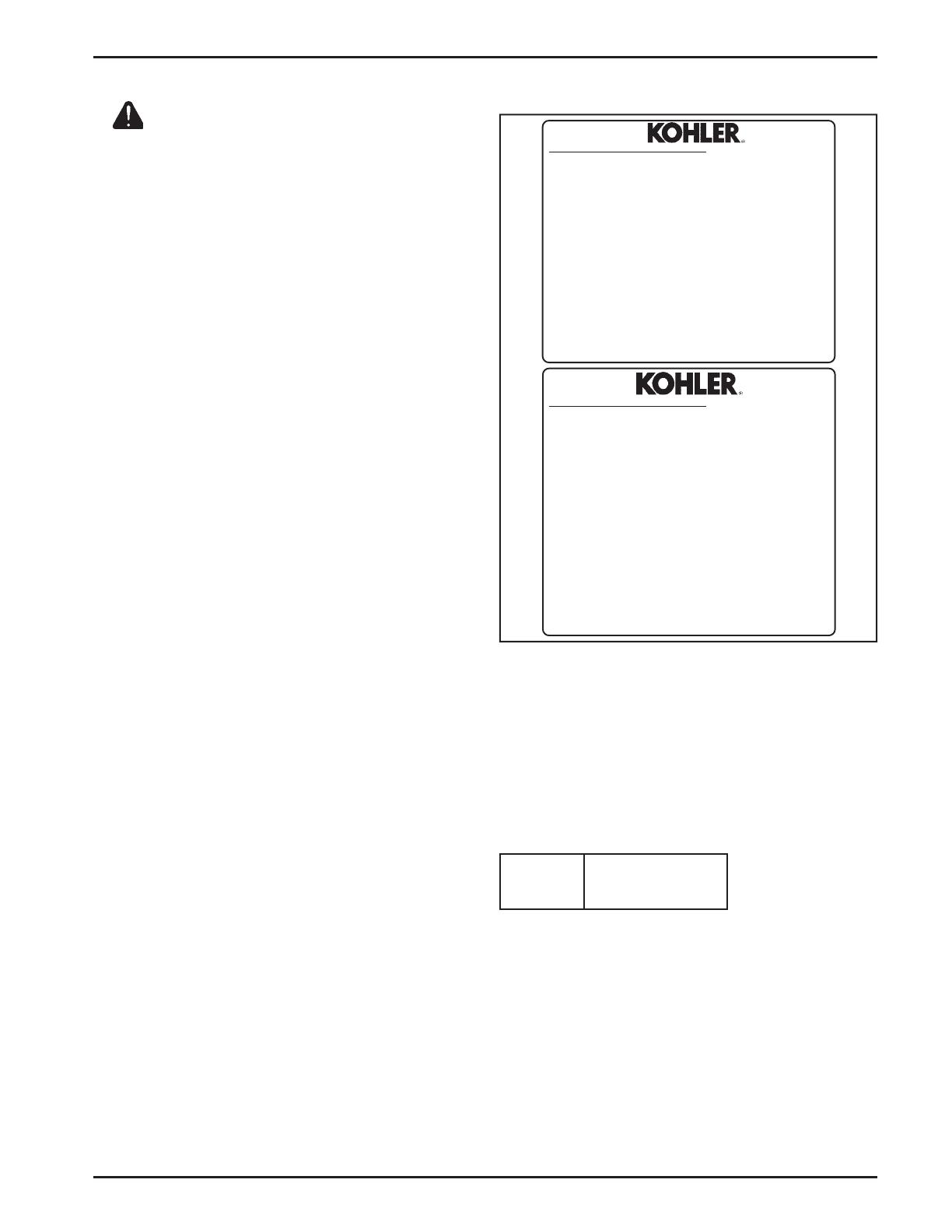
The engine identification numbers appear on a decal
affixed to the engine shrouding. Include letter suffixes,
if there are any.
Figure 4. Engine Identification Label.
The Emission Compliance Period referred to on the
Emission Control or Air Index label indicates the
number of operating hours for which the engine has
been shown to meet Federal emission requirements.
The following table provides the Engine Compliance
Period (in hours) associated with the category
descriptor found on the certification label.
Emission Compliance Period (Hours)
Record your engine identification numbers on the
identification label below (Figure 4) for future reference.
Refer to certification label for engine displacement.
Exhaust Emission Control System for models CH940-
CH1000 is EM.
Model Designation
Model CH980 for example: C designates Command
engine, H designates horizontal crankshaft, and 980
indicates the numerical model designation. A letter
suffix designates a specific version as follows:
Suffix Designates
S Electric Start
EPA
Category A
1000 hours
KOHLER CO. KOHLER, WISCONSIN USA
EMISSION COMPLIANCE PERIOD:
EPA:
CERTIFIED ON:
REFER TO OWNER'S MANUAL FOR HP RATING, SAFETY,
MAINTENANCE AND ADJUSTMENTS
1-800-544-2444 www.kohlerengines.com
FAMILY
DISPL. (CC)
MODEL NO.
SPEC. NO.
SERIAL NO.
BUILD DATE
OEM PROD. NO.
KOHLER CO. KOHLER, WISCONSIN USA
EMISSION COMPLIANCE PERIOD:
EPA:
CERTIFIED ON:
REFER TO OWNER'S MANUAL FOR HP RATING, SAFETY,
MAINTENANCE AND ADJUSTMENTS
1-800-544-2444 KohlerEngines.com
FAMILY
TYPE APP
DISPL. (CC)
MODEL NO.
SPEC. NO.
SERIAL NO.
BUILD DATE
OEM PROD. NO.
IMPORTANT ENGINE INFORMATION
THIS ENGINE MEETS EMISSION REGS FOR U.S. EPA 2006 AND
LATER AND EC STAGE II (SN:4) SI SMALL OFF–ROAD ENGINES
AND CA 2006 AND LATER LSI ENGINES
IMPORTANT ENGINE INFORMATION
THIS ENGINE MEETS EMISSION REGS FOR U.S. EPA PH 2 SMALL
OFF–ROAD ENGINES AND CA 2006 AND LATER LSI ENGINES
6
Operating Instructions
Also read the operating instructions of the equipment this engine powers.
Figure 6. Throttle and Choke Control Linkage in
Inner Pull Configuration.
WARNING: Lethal Exhaust Gases!
Engine exhaust gases contain poisonous carbon monoxide.
Carbon monoxide is odorless, colorless, and can cause death if
inhaled. Avoid inhaling exhaust fumes, and never run the
engine in a closed building or confined area.
Cold Weather Starting Hints
1. Be sure to use the proper oil for the temperature
expected. See Figure 2 on page 4.
2. Disengage all possible external loads.
3. Be sure the battery is in good condition. A warm
battery has much more starting capacity than a
cold battery.
4. Use fresh winter grade fuel. NOTE: Winter grade
gasoline has higher volatility to improve
starting. Do not use gasoline left over from
summer.
Starting
1. Place the throttle control midway between the
SLOW and FAST positions. Place the choke
control into the ON position. See Figures 7 and 8.
Figure 5. Throttle and Choke Control Linkage in
Outer Pull Configuration.
Pre-Start Checklist
Check oil level. Add oil if low. Do not overfill.
Check fuel level. Add fuel if low.
Check cooling air intake areas and external
surfaces of engine. Make sure they are clean and
unobstructed.
Check that the air cleaner components and all
shrouds, equipment covers, and guards are in
place and securely fastened.
Check that any clutches or transmissions are
disengaged or placed in neutral. This is especially
important on equipment with hydrostatic drive.
The shift lever must be exactly in neutral to
prevent resistance which could keep the engine
from starting.
Throttle and Choke Control Linkage Setup
The throttle and choke levers on these engines allow
remote mounted control operation from either side.
The linkage for the throttle and choke is connected in
one of the two available hole locations; A or B in the
control levers. Hole location A in each lever is used for
Outer Pull actuation. Hole Location B used for Inner
Pull actuation. Most engines will have the control
linkage connected in Location A, the primary location.
If the application requires opposite side control
direction or function, unhook the link(s) from the
small clip and reconnect in the other hole location. See
Figures 5 and 6.
Linkages
Connected Here
(A)
(A)
Linkages
Connected Here
(B)
(B)
7
Figure 8. Optional Control Panel with Engine
Mounted Controls.
2. Start the engine by activating the key switch.
Release the switch as soon as the engine starts.
NOTE: Do not crank the engine continuously for
more than 10 seconds at a time. If the engine
does not start, allow a 60 second cool down
period between starting attempts. Failure to
follow these guidelines can burn out, or
permanently damage, the starter motor.
NOTE: Upon start-up, a metallic ticking may occur.
This is caused by hydraulic lifter leakdown
during storage. Run the engine for 5 minutes.
The noise will normally cease in the first
minute. If noise continues, run the engine at
mid-throttle for 20 minutes. If noise persists,
take the engine to your local authorized
Kohler Engine Service Dealer.
NOTE: If the engine develops sufficient speed to
disengage the starter but does not keep
running (a false start), engine rotation must
be allowed to come to a complete stop before
attempting to restart the engine. If the starter
is engaged while the flywheel is rotating, the
starter pinion and flywheel ring gear may
clash resulting in damage to the starter.
Figure 7. Location of Control Levers.
If the starter does not turn the engine over, shut off
starter immediately. Do not make further attempts to
start the engine until the condition is corrected. Do not
jump start using another battery (refer to Battery on
this page). See your Kohler Engine Service Dealer for
service assistance.
3. For a Cold Engine – Gradually return the choke
control to the OFF position after the engine starts
and warms up.
The engine/equipment may be operated during
the warm-up period, but it may be necessary to
leave the choke partially on until the engine
warms up.
4. For a Warm Engine – Return choke to OFF
position as soon as engine starts.
Stopping
1. Remove the load by disengaging all PTO driven
attachments.
2. Position the throttle control somewhere between
half and full throttle; then stop the engine.
Battery
A 12 volt battery is normally used. Refer to the
operating instructions of the equipment this engine
powers for specific battery requirements.
If the battery charge is not sufficient to crank the
engine, recharge the battery (see page 14).
Operating
Angle of Operation
This engine will operate continuously at angles up to
25°. Check oil level to assure crankcase oil level is at
the F mark on the dipstick.
Refer to the operating instructions of the equipment
this engine powers. Because of equipment design or
application, there may be more stringent restrictions
regarding the angle of operation.
NOTE: Do not operate this engine continuously at
angles exceeding 25° in any direction. Engine
damage could result from insufficient
lubrication.
Cooling
NOTE: If debris builds up on the grass screen or
other cooling air intake areas, stop the engine
immediately and clean. Operating the engine
with blocked or dirty air intake and cooling
areas can cause extensive damage due to
overheating.
Control Panel
Control Lever
Knobs
Choke Lever
Throttle Lever
8
Check Oil Level
The importance of checking and maintaining the
proper oil level in the crankcase cannot be
overemphasized. Check oil BEFORE EACH USE as
follows:
1. Make sure the engine is stopped, level, and is cool
so the oil has had time to drain into the sump.
2. To keep dirt, debris, etc., out of the engine, clean
the area around the dipstick before removing it.
3. Remove the dipstick; wipe oil off. Reinsert the
dipstick into the tube and press all the way
down.
WARNING: Hot Parts!
Engine components can get extremely hot from operation. To
prevent severe burns, do not touch these areas while the engine
is running, or immediately after it is turned off. Never operate
the engine with heat shields or guards removed.
Engine Speed
NOTE: Do not tamper with the governor setting to
increase the maximum engine speed.
Overspeed is hazardous and will void the
engine warranty. The maximum allowable
high idle speed for these engines is 3900 RPM,
no load.
Maintenance Instructions
Maintenance, repair, or replacement of the emission control devices and systems, which are being done at the
customers expense, may be performed by any non-road engine repair establishment or individual. Warranty
repairs must be performed by an authorized Kohler service outlet.
WARNING: Accidental Starts!
Disabling engine. Accidental starting can cause severe injury or death. Before working on the engine or equipment, disable
the engine as follows: 1) Disconnect the spark plug lead(s). 2) Disconnect negative (-) battery cable from battery.
Maintenance Schedule
These required maintenance procedures should be performed at the frequency stated in the table. They should
also be included as part of any seasonal tune-up.
1
Perform these maintenance procedures more frequently under extremely dusty, dirty conditions.
2
Have a Kohler Engine Service Dealer perform this service.
Frequency
Maintenance
Daily or Before
Starting Engine
Fill fuel tank.
Check oil level.
Check air cleaner for dirty
1
, loose, or damaged parts.
• Check air intake and cooling areas, clean as necessary.
Seasonally or
Every 150 Hours
Replace air cleaner element
1
(flat air cleaner).
• Check heavy-duty air cleaner element.
Replace fuel filter.
Change oil. Oil filter is recommended. (More frequently under severe conditions.)
Remove cooling shrouds and clean cooling areas
1
.
Check oil cooler fins, clean as necessary.
Check spark plug condition and gap.
Change oil filter.
• Replace heavy-duty air cleaner element.
• Have solenoid shift starter disassembled and cleaned.
Have crankshaft splines lubricated
2
.
• Replace heavy-duty inner air cleaner element.
Replace spark plugs.
Every 200 Hours
Seasonally or
Every 300 Hours
Yearly or
Every 500 Hours
Every 600 Hours
Weekly
• Check filter minder or heavy-duty air cleaner element.
Every 25 Hours
• Service precleaner
1
(flat air cleaner).
9
Figure 9. Dipstick and Oil Fill.
4. Remove the dipstick and check the oil level. The
oil level should be up to, but not over, the F mark
on the dipstick. See Figure 10.
Figure 10. Oil Level Marks on Dipstick.
5. If the level is low, remove the cap from the valve
cover and add oil of the proper type, up to the F
mark on the dipstick. (Refer to Oil Type on page
4.) Always check the level with the dipstick
before adding more oil.
NOTE: To prevent extensive engine wear or damage,
always maintain the proper oil level in the
crankcase. Never operate the engine with the
oil level below the L mark or over the F mark
on the dipstick.
Oil Sentry
Most engines are equipped with an Oil Sentry
oil
pressure switch. On pressure switch equipped
models, if the oil pressure decreases below an
acceptable level, the Oil Sentry
will either shut off
the engine or activate a warning signal, depending on
the application. See Figure 11.
Figure 11. Oil Sentry
Pressure Switch.
NOTE: Make sure the oil level is checked BEFORE
EACH USE and is maintained up to the F
mark on the dipstick. This includes engines
equipped with Oil Sentry
systems.
Change Oil and Filter, Service Oil Cooler
Change Oil
Change oil seasonally or every 150 hours of operation,
(more frequently under severe conditions). Refill with
service class SJ or higher oil as specified in the
Viscosity Grades table (Figure 2) on page 4.
Change the oil while the engine is still warm. The oil
will flow more freely and carry away more
impurities. Make sure the engine is level when filling,
checking, and changing the oil.
Change the oil as follows (see Figures 12 and 13):
1. To keep dirt, debris, etc., out of the engine, clean
the area around the oil fill cap, dipstick and one of
the drain plugs.
2. Remove one of the oil drain plugs, oil fill cap, and
dipstick. Be sure to allow ample time for complete
drainage.
3. Reinstall the drain plug. Make sure it is tightened
to 21.4 N·m (15.7 ft. lb.) torque.
4. Fill the crankcase, with new oil of the proper
type, to the F mark on the dipstick. Refer to Oil
Type on page 4. Always check the level with the
dipstick before adding more oil.
5. Reinstall the oil fill cap and tighten securely.
Reinstall dipstick.
Oil Fill
Dipstick
Pressure Switch
Operating
Range
10
Figure 15. Optional Remote Mounted Oil Filter.
Replace the oil filter as follows:
1. Before removing the oil filter, clean the area
around the oil filter and housing to keep dirt and
debris out of the engine. Remove the old filter. On
crankcase mounted oil filter housings, a spring
loaded inner cup allows automatic oil drainback
into the crankcase as the oil filter is removed.
Wipe off the surface where the oil filter mounts.
2. Drain the oil from the engine crankcase.
3. Allow ample time for the oil to drain from the
crankcase.
4. Reinstall the drain plug and torque to 21.4 N·m
(15.7 ft. lb.).
5. Apply a thin film of clean oil to the rubber gasket
on the new filter.
6. Install the replacement oil filter. Turn the oil filter
clockwise until the rubber gasket contacts the oil
filter housing (not inner cup), then tighten the
filter an additional 3/4 to 1 turn.
7. Fill the crankcase with new oil of the proper type
to the F mark on the dipstick.
8. Start the engine and check for oil leaks. Correct
any leaks before placing the engine into service.
Check oil level to be sure it is up to but not over
the F mark.
Service Oil Cooler
Engines are equipped with an oil cooler mounted
under the No. 2 side cylinder shroud, separate from
the oil filter (see Figure 16).
Inspect and clean the oil cooler every 150 hours of
operation (more frequently under severe conditions).
Oil cooler must be kept free of debris.
Figure 13. Oil Drain Plug (No. 2 Side).
Change Oil Filter
The oil filter on most engines is located on top of the
crankcase between the cylinders. Some models use a
remote mounted oil filter. See Figures 14 and 15.
Replace the oil filter seasonally (150 hours), or at least
every other oil change (every 300 hours of operation).
Always use a genuine Kohler oil filter, Part No. 52 050 02-S.
Figure 14. Engine Mounted Oil Filter.
NOTE: To prevent extensive engine wear or damage,
always maintain the proper oil level in the
crankcase. Never operate the engine with the
oil level below the L mark or over the F mark
on the dipstick.
Figure 12. Oil Drain Plug (Starter Side).
Oil Filter
Oil Filter
Housing
Drain Plug
Drain Plug
11
To access and service the oil cooler, remove the top
mounting screw and loosen the two side screws, then
lift off the No. 2 side cylinder shroud. If required,
remove the two screws holding the oil cooler to the
blower housing. Pull the cooler away from the blower
housing. Clean both sides of the cooler with a brush as
shown in Figures 17 and 18, or with compressed air.
After cleaning, reattach the oil cooler to the lower
blower housing with the two mounting screws.
Figure 17. Cleaning Top of Oil Cooler.
Figure 16. Oil Cooler.
Air Cleaners
These engines use a heavy-duty style air cleaner (see
Figure 19) or a flat air cleaner (see Figure 23). These
systems are CARB/EPA certified and the components
should not be altered or modified in any way.
NOTE: Lift or move this engine using the lifting
strap and lifting point shown in Figure 1.
DO NOT lift the engine by the air cleaner.
Heavy-Duty Air Cleaner
The heavy-duty air cleaner consists of a cylindrical
housing mounted to the carburetor and intake
manifold. The housing contains a paper element and
inner element, designed for longer service intervals.
Figure 19. Heavy-Duty Style Air Cleaner.
Service
Weekly and every 150 hours: Check filter minder (if
equipped), unhook the two retaining clips on each end
and remove the end caps. Perform inspection of the
paper element and inlet screen area.
Seasonally or every 300 hours of operation (more
often under extremely dusty or dirty conditions),
replace the paper element and check the inner
element. Follow these steps.
1. Unhook the two retaining clips on each end and
remove the end caps from the air cleaner housing.
2. Check and clean the screen area on the inlet side.
Pull the air cleaner paper element out of the
housing on opposite side. See Figures 20 and 21.
Figure 18. Cleaning Underside of Oil Cooler.
Figure 20. Accessing Inlet Screen.
Oil Cooler
Inlet
Screen
12
Figure 21. Removing Elements.
3. After the paper element is removed, check the
condition of the inner element. It should be
replaced whenever it appears dirty, typically
every other time the paper element is replaced or
every 600 hours. Clean the area around the base
of the inner element before removing it, so dirt
does not get into the engine.
4. Do not wash the paper element and inner
element or use compressed air, this will damage
the elements. Replace dirty, bent or damaged
elements with new genuine Kohler elements as
required. Handle the new elements carefully; do
not use if the sealing surfaces are bent or
damaged.
5. Check all parts for wear, cracks, or damage, and
make sure ejector area is clean. See Figure 22.
Replace any damaged components.
Figure 22. Ejector Area.
6. Install the new inner element, Kohler Part No.
25 083 04-S followed by the paper element, Part
No. 25 083 01-S. Slide each fully into place in the
air cleaner housing.
7. Reinstall the end caps and secure with the
retaining clips. See Figure 19.
Paper Element
Inner
Element
Ejector
Area
Flat Air Cleaner
The flat air cleaner has a replaceable, high density
paper air cleaner element. Some engines are also
equipped with an oiled, foam precleaner which
surrounds the paper element. See Figure 23.
Figure 23. Flat Air Cleaner.
Service Precleaner
If so equipped, wash and reoil the precleaner every 25
hours of operation (more often under extremely dusty
or dirty conditions).
1. Loosen the cover retaining knobs and remove the
cover.
2. Remove the precleaner from the paper element.
3. Wash the precleaner in warm water with
detergent. Rinse the precleaner thoroughly until
all traces of detergent are eliminated. Squeeze out
excess water (do not wring). Allow the precleaner
to air dry.
4. Saturate the precleaner with new engine oil.
Squeeze out all excess oil.
5. Reinstall the precleaner over the paper element.
6. Reinstall the air cleaner cover. Secure cover with
the cover retaining knobs.
7. When precleaner replacement is necessary, order
genuine Kohler parts.
Element
Precleaner
Cover Knobs
Air Cleaner
Cover
Element Latch
13
Ignition System
An electronic Capacitive Discharge (CD) ignition
system is used. Other than periodically checking/
replacing the spark plugs, no maintenance, timing, or
adjustments are necessary or possible with this
system.
Check Spark Plugs
Every 200 hours of operation, remove the spark plugs,
check condition, and reset the gap. Replace with new
plugs every 600 hours, or as necessary. The standard
spark plug is a Champion
®
XC10YC (Kohler Part No.
62 132 04-S). Equivalent alternate brand plugs can
also be used.
1. Before removing the spark plug, clean the area
around the base of the plug to keep dirt and
debris out of the engine.
2. Remove the plug and check its condition. Replace
the plug if worn or reuse is questionable.
NOTE: Do not clean the spark plug in a machine
using abrasive grit. Some grit could remain
in the spark plug and enter the engine
causing extensive wear and damage.
3. Check the gap using a wire feeler gauge. Adjust
the gap to 0.76 mm (0.030 in.) by carefully
bending the ground electrode. See Figure 24.
Figure 24. Servicing Spark Plug.
4. Reinstall the spark plug into the cylinder head.
Torque the spark plug to 24.4-29.8 N·m
(18-22 ft. lb.).
Service Paper Element
Every 150 hours of operation (more often under
extremely dusty or dirty conditions) replace the paper
element.
1. Loosen the cover retaining knobs and remove the
cover.
2. Rotate the element latch to release the element.
3. Remove the paper element with precleaner.
4. Remove the precleaner (if so equipped) from the
paper element. Service the precleaner as
described above.
5. Do not wash the paper element or use
pressurized air, as this will damage the element.
Replace a dirty, bent, or damaged element with a
genuine Kohler element. Handle new elements
carefully; do not use if the sealing surfaces are
bent or damaged.
6. When servicing the air cleaner, check the air
cleaner base. Make sure it is secured and not bent
or damaged. Replace all damaged air cleaner
components.
NOTE: If any loose dirt or debris fell on the air
cleaner base when the element was
removed, carefully remove it and wipe
the base clean. Be careful that none of it
drops into the intake throat.
7. Reinstall the paper element with precleaner.
Rotate the element latch to secure the element.
8. Reinstall the air cleaner cover. Secure cover with
the cover retaining knobs.
9. When element replacement is necessary, order
genuine Kohler parts.
Clean Air Intake/Cooling Areas
To ensure proper cooling, make sure the grass screen,
cooling fins, and other external surfaces of the engine
are kept clean at all times.
NOTE: Operating the engine with a blocked grass
screen, dirty or plugged cooling fins, and/or
cooling shrouds removed, will cause engine
damage due to overheating.
Wire Gauge
Ground
Electrode
Spark Plug
0.76 mm
(0.030 in.) Gap
14
Figure 26. Keihin Two-Barrel Carburetor.
NOTE: Carburetor adjustments should be made only
after the engine has warmed up.
NOTE: To ensure correct engine operation at altitudes
above 1525 meters (5000 ft.), it may be
necessary to have an authorized Kohler dealer
install a special high-altitude jet kit in the
carburetor. If a high-altitude kit has been
installed, the engine must be reconverted to
the original jet size, before it is operated at
lower altitudes, or overheating and engine
damage can result.
Troubleshooting
If engine troubles are experienced that appear to be fuel
system related, check the following areas before
adjusting the carburetor.
Make sure the fuel tank is filled with clean, fresh
gasoline.
Make sure the fuel tank cap vent is not blocked and
that it is operating properly.
If the fuel tank is equipped with a shut-off valve,
make sure it is open.
If the engine is equipped with an in-line fuel filter,
make sure it is clean and unobstructed. Replace the
filter if necessary.
Make sure fuel is reaching the carburetor. This
includes checking the fuel lines and fuel pump for
restrictions or faulty components, replace as
necessary.
Make sure the air cleaner element is clean and all
air cleaner element components are fastened
securely.
If, after checking the items listed above, the engine is
hard to start, runs roughly, or stalls at low idle speed, it
may be necessary to adjust or service the carburetor.
Figure 25. Low Permeation Fuel Line.
Carburetor Troubleshooting and
Adjustments
These engines use a Keihin BK two-barrel carburetor
with fixed main jets, and fixed or limiter-equipped
low idle fuel adjusting needles. See Figure 26. In
compliance with government emission standards, the
carburetor is calibrated to deliver the correct fuel-to-
air mixture to the engine under all operating
conditions. Adjustments are made as follows.
Battery Charging
WARNING: Explosive Gas!
Batteries produce explosive hydrogen gas while being charged.
To prevent a fire or explosion, charge batteries only in well
ventilated areas. Keep sparks, open flames, and other sources of
ignition away from the battery at all times. Keep batteries out of
the reach of children. Remove all jewelry when servicing
batteries.
Before disconnecting the negative (-) ground cable, make sure
all switches are OFF. If ON, a spark will occur at the ground
cable terminal which could cause an explosion if hydrogen gas
or gasoline vapors are present.
NOTE: Do not apply 12 volt DC to kill terminal of
ignition module.
Fuel System
Fuel Filter
Most engines are equipped with an in-line fuel filter.
Periodically inspect the filter and replace with a
genuine Kohler filter seasonally or every 150
operating hours.
Fuel Line
These engines use Low Permeation SAE 30 R7 rated
fuel line; certified to meet emission requirements.
Standard fuel line may not be used. Order
replacement hose by part number through a Kohler
Engine Service Dealer.
Drain Screw
Idle Speed (RPM)
Adjustment Screw
Idle Fuel
Adjustments
Vacuum Port
15
Adjust Carburetor
Low Idle Speed (RPM) and Governed Idle
Adjustment
1. Low Idle Speed (RPM) Setting: Place the throttle
control into the idle or slow position. Hold the
governor lever away from carburetor so the
throttle lever is against the Idle Speed (RPM)
Adjustment Screw of carburetor. See Figure 26.
Set the low idle speed to 1200 RPM* (± 75 RPM)
by turning the low idle speed adjusting screw on
carburetor in or out. Check the speed using a
tachometer.
*NOTE: The actual low idle speed depends on the
application. Refer to the equipment
manufacturers recommendations. The low
idle speed for basic engines is 1200 RPM. To
ensure best results when setting the low idle
fuel needle, the low idle speed should be 1200
RPM (± 75 RPM).
2. Release the governor lever and check that the
throttle lever is in the idle position. Turn the
governed idle (outer) adjustment screw on main
control bracket to obtain the equipment
manufacturer's recommended idle speed (1400-
1800 RPM). See Figure 27.
Governed Idle
Speed Screw
High Speed
Adjustment Screw
Lean
Rich
Adjust to
Midpoint
Lean
Rich
Adjust to
Midpoint
Left Side Right Side
2. Place the throttle control into the idle or slow
position. Adjust the low idle speed to 1200 RPM*.
Follow the Adjusting the Low Idle Speed (RPM)
procedure.
3. Low Idle Fuel Needle(s) Setting: Place the
throttle into the idle or slow position.
a. Turn one of the low idle fuel adjusting needles
out (counterclockwise) from the preliminary
setting until the engine speed decreases (rich).
Note the position of the needle. Now turn the
adjusting needle in (clockwise). The engine
speed may increase, then it will decrease as
the needle is turned in (lean). Note the
position of the needle. Set the adjusting needle
midway between the rich and lean settings.
See Figure 28.
b. Repeat the procedure on the other low idle
adjustment needle.
4. Recheck/adjust the Low Idle Speed (RPM), to the
specified setting.
Figure 28. Optimum Low Idle Fuel Settings.
High Speed (RPM) Adjustment
The high speed RPM (inner) adjustment screw is
preset at the factory and normally does not need
readjustment.
Figure 27. Adjusting Governed Idle Speed Screw.
Low Idle Fuel Adjustment
NOTE: Engines will have fixed low idle or limiter
caps on the two idle fuel adjusting needles.
Step 3 can only be performed within the
limits allowed by the cap. Do not attempt to
remove the limiter caps.
1. Start the engine and run at half throttle for 5 to
10 minutes to warm up. The engine must be
warm before doing steps 2, 3 and 4.
16
Troubleshooting
When troubles occur, be sure to check the simple causes which, at first, may seem too obvious to be considered.
For example, a starting problem could be caused by an empty fuel tank. Some common causes of engine troubles
are listed in the following table.
Do not attempt to service or replace major engine components, or any items that require special timing or
adjustment procedures. Have your Kohler Engine Service Dealer do this work.
Possible Cause No Improper Dirt In Dirty Incorrect Engine Dirty Air Faulty
Problem Fuel Fuel Fuel Line/System Grass Screen Oil Level Overloaded Cleaner Spark Plug
Will Not Start ••
Hard Starting ••
Stops Suddenly ••
Lacks Power ••
Operates Erratically ••
Knocks or Pings ••
Skips or Misfires ••
Backfires ••
Overheats ••
High Fuel Consumption ••
Storage
If the engine will be out of service for 30 days or more,
use the following storage procedure:
1. Clean the exterior surfaces of the engine. Avoid
spraying water at the wiring harness or any of
the electrical components.
2. Change the oil and filter while the engine is still
warm from operation. Refer to Change Oil and
Change Oil Filter on pages 9 and 10.
3. The fuel system must be completely emptied, or
the gasoline must be treated with a stabilizer to
prevent deterioration. If you choose to use a
stabilizer, follow the manufacturers
recommendations, and add the correct amount
for the capacity of the fuel system. Fill the fuel
tank with clean, fresh gasoline. Run the engine for
2-3 minutes to get stabilized fuel into the rest of
the system. Close fuel shut-off valve when unit is
being stored or transported.
To empty the system, run the engine until the
tank and fuel system are empty.
4. Remove the spark plugs. Add one tablespoon of
engine oil into each spark plug hole. Install the
plugs, but do not connect the plug leads. Crank
the engine two or three revolutions.
5. Store the engine in a clean, dry place.
Parts Ordering
The engine Specification, Model, and Serial Numbers
are required when ordering replacement parts from
your Kohler Engine Service Dealer. These numbers are
found on the identification plate which is affixed to the
engine shrouding. Include letter suffixes if there are
any. Refer to Engine Identification Numbers on page 5.
Always insist on genuine Kohler parts. All genuine Kohler
parts meet strict standards for fit, reliability, and
performance.
Major Repair
Major repair information is available in Kohler Engine
Service Manuals. This type of repair generally requires
the services of a trained mechanic and the use of special
tools and equipment. Kohler Engine Service Dealers
have the facilities, training, and genuine Kohler
replacement parts necessary to perform this service.
For the nearest Sales & Service location:
• visit our website www.kohlerengines.com
call 1-800-544-2444 (U.S. & Canada)
look in the local telephone directory under
Engines-Gasoline
17
Specifications
Model: ................................................................... CH940 .................... CH960 .................. CH980 .............................. CH1000
Bore: ................................................ mm (in.) ..... 90 (3.54) ................. 90 (3.54) ............... 90 (3.54) ........................... 90 (3.54)
Stroke: .............................................mm (in.) ..... 78.5 (3.1) ................ 78.5 (3.1) .............. 78.5 (3.1) .......................... 78.5 (3.1)
Displacement: ...............................cm
3
(in
3
) ..... 999 (61) .................. 999 (61) ................ 999 (61) ............................ 999 (61)
Power (@3600 RPM): .....................kW (HP) ..... 25.4 (34*)................ 26.9 (36*) .............. 28.3 (38*).......................... 29.8 (40*)
Compression Ratio: ........................................... 8.8:1 ........................ 8.8:1 ...................... 8.8:1 .................................. 8.8:1
Weight: ............................................... kg (lb.) ..... 59.8 (132) ............... 59.8 (132) ............. 59.8 (132) ......................... 59.8 (132)
Oil Capacity (w/filter) - approximate,
determined by oil filter used:
____________________________
2.7 L (2.9 U.S. qt.)
__________________________________
Lubrication:
________________________________________
Full Pressure w/full Flow Filter
______________________________
Exhaust Emission Control System for models CH940-CH1000 is EM.
*Horsepower ratings exceed Society of Automotive Engineers Small Engine Test Code J1940. Actual engine
horsepower is lower and affected by, but not limited to, accessories (air cleaner, exhaust, charging,
cooling, fuel pump, etc.), application, engine speed and ambient operating conditions (temperature,
humidity, and altitude). Kohler reserves the right to change product specifications, designs and
equipment without notice and without incurring obligation.
LIMITED 2 YEAR COMMAND PRO ENGINE WARRANTY
Kohler Co. warrants to the original consumer that each new COMMAND PRO engine sold by Kohler Co. will be free from
manufacturing defects in materials or workmanship in normal service for a period of two (2) years from date of purchase, provided it
is operated and maintained in accordance with Kohler Co.’s instructions and manuals.
Our obligation under this warranty is expressly limited, at our option, to the replacement or repair at Kohler Co., Kohler, Wisconsin
53044, or at a service facility designated by us of such parts as inspection shall disclose to have been defective.
EXCLUSIONS
Mufflers on engines used commercially (non-residential) are warranted for one (1) year from date of purchase, except catalytic
mufflers, which are warranted for two (2) years.
This warranty does not apply to defects caused by casualty or unreasonable use, including faulty repairs by others and failure to
provide reasonable and necessary maintenance.
The following items are not covered by this warranty:
Engine accessories such as fuel tanks, clutches, transmissions, power-drive assemblies, and batteries, unless supplied or installed by
Kohler Co. These are subject to the warranties, if any, of their manufacturers.
KOHLER CO. AND/OR THE SELLER SHALL NOT BE LIABLE FOR SPECIAL, INDIRECT, INCIDENTAL, OR CONSEQUENTIAL
DAMAGES OF ANY KIND, including but not limited to labor costs or transportation charges in connection with the repair or
replacement of defective parts.
IMPLIED OR STATUTORY WARRANTIES, INCLUDING WARRANTIES OF MERCHANTABILITY OR FITNESS FOR A
PARTICULAR PURPOSE, ARE EXPRESSLY LIMITED TO THE DURATION OF THIS WRITTEN WARRANTY. We make no other
express warranty, nor is any one authorized to make any on our behalf.
Some states do not allow limitations on how long an implied warranty lasts, or the exclusion or limitation of incidental or
consequential damages, so the above limitation or exclusion may not apply to you.
This warranty gives you specific legal rights, and you may also have other rights which vary from state to state.
TO OBTAIN WARRANTY SERVICE
Purchaser must bring the engine to an authorized Kohler service facility. To locate the nearest facility, visit our website,
www.kohlerengines.com, consult your local telephone directory, or telephone 1-800-544-2444.
ENGINE DIVISION, KOHLER CO., KOHLER, WISCONSIN 53044
18
KOHLER CO.
FEDERAL AND CALIFORNIA EMISSION CONTROL SYSTEMS
LIMITED WARRANTY
SMALL OFF-ROAD AND CLASS 1 LSI ENGINES
The U.S. Environmental Protection Agency (EPA), the California Air Resources Board (CARB), and Kohler Co. are pleased to
explain the Federal and California Emission Control Systems Warranty on your off-road equipment engine. In California beginning
in 2006, "emissions" means both exhaust and evaporative emissions. For California, small off-road engines produced in 2006 and
later, and Class 1 LSI (Large Spark Ignited engines at or below 1.0 liter) produced in 2002 and later, must be designed, built and
equipped to meet the state’s stringent anti-smog standards. In other states, 1997 and later model year engines must be designed,
built and equipped, to meet the U.S. EPA regulations for small non-road engines. The engine must be free from defects in materials
and workmanship, which cause it to fail to conform with U.S. EPA standards for the first two years of engine use from the date of
sale to the ultimate purchaser. Kohler Co. must warrant the emission control system on the engine for the period of time listed
above, provided there has been no abuse, neglect or improper maintenance.
The emission control system may include parts such as the carburetor or fuel injection system, the ignition system, and catalytic
converter. Also included are the hoses, belts and connectors and other emission
related assemblies.
Where a warrantable condition exists, Kohler Co. will repair the engine at no cost, including diagnosis (if the diagnostic work is
performed at an authorized dealer), parts and labor.
MANUFACTURER’S WARRANTY COVERAGE
Small off-road engines produced in 2006 or later, and Class 1 LSI engines produced in 2002 and later, are warranted for two years
in California. In other states, 1997 and later model year engines are warranted for two years. If any emission related part on the
engine is defective, the part will be repaired or replaced by Kohler Co. free of charge.
OWNER’S WARRANTY RESPONSIBILITIES
(a) The engine owner is responsible for the performance of the required maintenance listed in the owners manual. Kohler Co.
recommends that you retain all receipts covering maintenance on the engine, but Kohler Co. cannot deny warranty solely
for the lack of receipts or for your failure to assure that all scheduled maintenance was performed.
(b) Be aware, however, that Kohler Co. may deny warranty coverage if the engine or a part has failed due to abuse, neglect,
improper maintenance or unapproved modifications.
(c) For warranty repairs, the engine must be presented to a Kohler Co. service center as soon as a problem exists. Call
1-800-544-2444 or access our website at: www.kohlerengines.com, for the names of the nearest service centers. The
warranty repairs should be completed in a reasonable amount of time, not to exceed 30 days.
If you have any questions regarding warranty rights and responsibilities, you should contact Kohler Co. at 1-920-457-4441 and
ask for an Engine Service representative.
COVERAGE
Kohler Co. warrants to the ultimate purchaser and each subsequent purchaser that the engine will be designed, built and equipped,
at the time of sale, to meet all applicable regulations. Kohler Co. also warrants to the initial purchaser and each subsequent
purchaser, that the engine is free from defects in materials and workmanship which cause the engine to fail to conform with
applicable regulations for a period of two years.
Small off-road engines produced in 2006 or later, and Class 1 LSI engines produced in 2002 and later, are warranted for two years
in California. For 1997 and later model years, EPA requires manufacturers to warrant engines for two years in all other states.
These warranty periods will begin on the date the engine is purchased by the initial purchaser. If any emission related part on the
engine is defective, Kohler Co. will replace the part at no cost to the owner. Kohler Co. is liable for damages to other engine
components caused by the failure of a warranted part still under warranty.
Kohler Co. shall remedy warranty defects at any authorized Kohler Co. engine dealer or warranty station. Warranty repair work
done at an authorized dealer or warranty station shall be free of charge to the owner if such work determines that a warranted part
is defective.
19
Listed below are the parts covered by the Federal and California Emission Control Systems Warranty. Some parts listed below
may require scheduled maintenance and are warranted up to the first scheduled replacement point for that part. The warranted
parts include the following if they were present in the engine purchased:
Oxygen sensor (if equipped) Ignition module(s) with high tension lead
Intake manifold (if equipped) Gaseous fuel regulator (if equipped)
Exhaust manifold (if equipped) Electronic control unit (if equipped)
Catalytic muffler (if equipped) Carburetor or fuel injection system
Thermal reactor muffler (if equipped) Fuel metering valve (if equipped)
Fuel lines, fuel line fittings and clamps (if equipped) Air filter, fuel filter, and spark plugs (only
Spark advance module (if equipped) to first scheduled replacement point)
Crankcase breather Evaporative System (if equipped)
Air Injection System (if equipped) - Canister (if equipped)
- Air pump or pulse valve assembly (if equipped) - Canister filter (if equipped)
- Control/distribution valve (if equipped) - Vapor hose (if equipped)
- Distribution manifold (if equipped) - Orifice connector (if equipped)
- Air hoses (if equipped) - Fuel tank (if equipped)
- Vacuum lines (if equipped) - Fuel cap (if equipped)
- Primer bulb canister (if equipped)
LIMITATIONS
This Emission Control Systems Warranty shall not cover any of the following:
(a) repair or replacement required because of misuse or neglect, improper maintenance, repairs improperly performed or
replacements not conforming to Kohler Co. specifications that adversely affect performance and/or durability and
alterations or modifications not recommended or approved in writing by Kohler Co.,
(b) replacement of parts and other services and adjustments necessary for required maintenance at and after the first scheduled
replacement point,
(c) consequential damages such as loss of time, inconvenience, loss of use of the engine or equipment, etc.,
(d) diagnosis and inspection fees that do not result in eligible warranty service being performed, and
(e) any add-on or modified part, or malfunction of authorized parts due to the use of add-on or modified parts.
MAINTENANCE AND REPAIR REQUIREMENTS
The owner is responsible for the proper use and maintenance of the engine. Kohler Co. recommends that all receipts and records
covering the performance of regular maintenance be retained in case questions arise. If the engine is resold during the warranty
period, the maintenance records should be transferred to each subsequent owner. Kohler Co. reserves the right to deny warranty
coverage if the engine has not been properly maintained; however, Kohler Co. may not deny warranty repairs solely because of
the lack of repair maintenance or failure to keep maintenance records.
Normal maintenance, replacement or repair of emission control devices and systems may be performed by any repair
establishment or individual; however, warranty repairs must be performed by a Kohler authorized service center. Any
replacement part or service that is equivalent in performance and durability may be used in non-warranty maintenance or repairs,
and shall not reduce the warranty obligations of the engine manufacturer.
ENGINE DIVISION, KOHLER CO., KOHLER, WISCONSIN 53044
FOR SALES AND SERVICE INFORMATION
IN U.S. AND CANADA, CALL 1-800-544-2444
LITHO IN U.S.A.
FORM NO.: 62 590 01-A
ISSUED: 1/07
REVISED: 4/09
KohlerEngines.com
1 / 1

Kohler CH1000 User manual

Category
Garden tools
Type
User manual
This manual is also suitable for

Ask a question and I''ll find the answer in the document

Finding information in a document is now easier with AI

Ask the document