Smooth Fitness V2300 User manual
- Type
- User manual
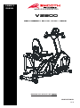
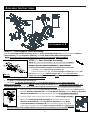
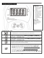
Smooth Fitness V2300 is a 2-in-1 recumbent elliptical/bike designed for semi-commercial, light-commercial, and home usage. The equipment can be used by only one person at a time and is suitable for users weighing up to 300 pounds. The V2300 features a pulse sensor to monitor heart rate and a console that displays workout metrics such as time, distance, calories burned, and speed. The recumbent elliptical/bike has adjustable resistance levels, allowing users to customize their workouts based on their fitness level and goals.
Smooth Fitness V2300 is a 2-in-1 recumbent elliptical/bike designed for semi-commercial, light-commercial, and home usage. The equipment can be used by only one person at a time and is suitable for users weighing up to 300 pounds. The V2300 features a pulse sensor to monitor heart rate and a console that displays workout metrics such as time, distance, calories burned, and speed. The recumbent elliptical/bike has adjustable resistance levels, allowing users to customize their workouts based on their fitness level and goals.


-
 1
1
-
 2
2
-
 3
3
-
 4
4
-
 5
5
-
 6
6
-
 7
7
-
 8
8
-
 9
9
-
 10
10
-
 11
11
-
 12
12
-
 13
13
-
 14
14
-
 15
15
-
 16
16
-
 17
17
-
 18
18
-
 19
19
-
 20
20
-
 21
21
-
 22
22
-
 23
23
-
 24
24
-
 25
25
-
 26
26
-
 27
27
-
 28
28
-
 29
29


Smooth Fitness V2300 User manual
- Type
- User manual
Smooth Fitness V2300 is a 2-in-1 recumbent elliptical/bike designed for semi-commercial, light-commercial, and home usage. The equipment can be used by only one person at a time and is suitable for users weighing up to 300 pounds. The V2300 features a pulse sensor to monitor heart rate and a console that displays workout metrics such as time, distance, calories burned, and speed. The recumbent elliptical/bike has adjustable resistance levels, allowing users to customize their workouts based on their fitness level and goals.
Ask a question and I''ll find the answer in the document
Finding information in a document is now easier with AI
Related papers
-
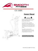 Smooth Fitness CE-3.0DS User manual
-
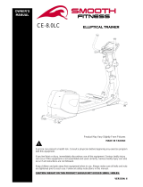 Smooth Fitness CE-8.0LC Owner's manual
-
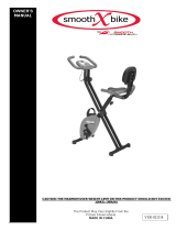 Smooth Fitness SMB-XBIKE Owner's manual
-
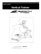
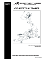 Smooth Fitness VT-3.4 Owner's manual
-
 Smooth Fitness CE 2.1 User manual
-
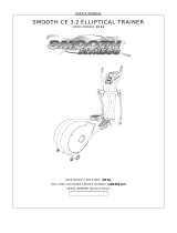 Smooth Fitness CE 3.2 User manual
-
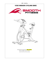 Smooth Fitness V350 User manual
-
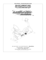 Smooth Fitness SB4 User manual
-
 Smooth Fitness E4250 Owner's manual
-
 Smooth Fitness SNC‐16 Owner's manual


Other documents
-
Boss Office Products B1002-BK Operating instructions
-
Boss Office Products B6338 Installation guide
-
Titan Fitness Stall Bars - Set of 4 User manual
-
 Living Spaces A629-29 User manual
-
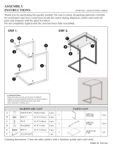
ROOMS TO GO 20010675 Assembly Instructions
-
Disney 38209929 Assembly Instructions
-
Vision Fitness T8200HRC User manual
-
-
-
 Tortuga Outdoor PSR2-C-WH Operating instructions

