Smeg SCB80GX User manual

Category
Kitchen & houseware accessories
Type
User manual

This manual is also suitable for

Smeg SCB80GX is a multifunctional gas-powered cooking appliance that combines a gas hob, oven, and grill, offering versatile cooking options for various culinary needs. It features four gas burners on the hob, including auxiliary, semi-rapid, rapid, and triple crown burners, providing a range of heating capacities for different cooking tasks. The oven, with a 66-liter capacity, allows for spacious cooking, while the grill function adds the ability to grill and brown food.

Smeg SCB80GX is a multifunctional gas-powered cooking appliance that combines a gas hob, oven, and grill, offering versatile cooking options for various culinary needs. It features four gas burners on the hob, including auxiliary, semi-rapid, rapid, and triple crown burners, providing a range of heating capacities for different cooking tasks. The oven, with a 66-liter capacity, allows for spacious cooking, while the grill function adds the ability to grill and brown food.

Contents
3
1 INSTRUCTIONS FOR SA
F
E AND PROPER US
E
_
______________________________
4
2 INSTALLATION OF THE APPLIANCE ________________________________________6
3 ADAPTATION TO DIFFERENT TYPES OF GAS ________________________________8
4 FINAL OPERATIONS ____________________________________________________11
5 DESCRIPTION OF FRONT PANEL CONTROLS _______________________________13
6 USE OF THE COOKING HOB______________________________________________15
7 USE OF THE OVEN _____________________________________________________16
8 ELECTRONIC PROGRAMMER (ONLY ON EQUIPPED MODELS)_________________20
9 DIGITAL TIMER (CERTAIN MODELS ONLY)__________________________________22
10 ANALOGUE CLOCK (ONLY ON EQUIPPED MODELS) _________________________22
11 CLEANING AND MAINTENANCE ___________________________________________23
12 EXTRAORDINARY MAINTENANCE _________________________________________25
THESE INSTRUCTIONS ARE VALID ONLY FOR END USER COUNTRIES WHOSE
IDENTIFICATION SYMBOLS APPEAR ON THE COVER OF THIS MANUAL.
INSTRUCTIONS FOR THE INSTALLER: these are for the qualified technician who must carry out a
suitable check of the gas system, install the appliance, set it functioning and carry out an inspection
test.
INSTRUCTIONS FOR THE USER: these contain user advice, description of the commands and the
correct procedures for cleaning and maintenance of the appliance.
Introduction
4
1 INSTRUCTIONS FOR SAFE AND PROPER USE
THIS MANUAL IS AN INTEGRAL PART OF THE APPLIANCE AND THEREFORE MUST BE KEPT
IN ITS ENTIRETY AND IN AN ACCESSIBLE PLACE FOR THE WHOLE WORKING LIFE OF THE
COOKER. WE ADVISE READING THIS MANUAL AND ALL THE INSTRUCTIONS THEREIN
BEFORE USING THE COOKER. ALSO KEEP THE SERIES OF NOZZLES SUPPLIED.
INSTALLATION MUST BE CARRIED OUT BY QUALIFIED PERSONNEL IN ACCORDANCE WITH
THE REGULATIONS IN FORCE. THIS APPLIANCE IS INTENDED FOR DOMESTIC USES AND
CONFORMS TO CURRENT REGULATIONS IN FORCE. THE APPLIANCE HAS BEEN BUILT TO
CARRY OUT THE FOLLOWING FUNCTIONS: COOKING AND HEATING-UP OF FOOD. ALL
OTHER USES ARE CONSIDERED IMPROPER.
THE MANUFACTURER DECLINES ALL RESPONSIBILITY FOR IMPROPER USE.
DO NOT LEAVE THE PACKING IN THE HOME ENVIRONMENT. SEPARATE THE VARIOUS
WASTE MATERIALS AND TAKE THEM TO THE NEAREST SPECIAL GARBAGE COLLECTION
CENTRE.
IT IS OBLIGATORY FOR THE ELECTRICAL SYSTEM TO BE GROUNDED ACCORDING TO THE
METHODS REQUIRED BY SAFETY RULES.
WHEN LINKING UP TO MAINS BY PLUG AND SOCKET, MAKE SURE THAT BOTH ARE
COMPATIBLE AND CONNECT BY MEANS OF A POWER CABLE COMPLYING WITH
APPLICABLE REGULATIONS.
THE SOCKET MUST BE ACCESSIBLE AFTER THE APPLIANCE HAS BEEN BUILT IN.
NEVER UNPLUG BY PULLING ON THE CABLE.
IMMEDIATELY AFTER INSTALLATION CARRY OUT A BRIEF INSPECTION TEST OF THE
APPLIANCE, FOLLOWING THE INSTRUCTIONS BELOW. SHOULD THE APPLIANCE NOT
FUNCTION, DISCONNECT IT FROM THE SUPPLY AND CALL THE NEAREST TECHNICAL
ASSISTANCE CENTRE.
NEVER ATTEMPT TO REPAIR THE APPLIANCE.
WHEN NOT IN USE, MAKE SURE THAT THE CONTROL KNOBS ARE IN THE CORRECT (OFF)
POSITION
.
NEVER PUT INFLAMMABLE OBJECTS IN THE OVEN: THEY COULD BE ACCIDENTALLY
LIGHTED AND CAUSE FIRES.
THE I.D. PLATE WITH TECHNICAL DATA, REGISTRATION NUMBER AND BRAND NAME IS
POSITIONED VISIBLY IN THE STORAGE COMPARTMENT.
THE PLATE MUST NOT BE REMOVED.
DO NOT PUT PANS WITHOUT PERFECTLY SMOOTH AND FLAT BOTTOMS ON THE COOKING
hob GRIDS.
DO NOT USE CONTAINERS OR BROILERS THAT EXTEND BEYOND THE OUTER PERIMETER
OF THE HOB.
Introduction
5
LOWER THE GLASS COVER SLOWLY AND BY HAND.
WARNING: THE GLASS COVER MAY SHATTER IF IT OVERHEATS. SWITCH OFF ALL RINGS
AND WAIT FOR THEM TO COOL DOWN BEFORE CLOSING THE COVER.
DURING USE THE APPLIANCE BECOMES VERY HOT. TAKE CARE NOT TO TOUCH THE
HEATING ELEMENTS INSIDE THE OVEN.
THE APPLIANCE IS DESIGNED FOR USE BY ADULTS. DO NOT ALLOW CHILDREN TO GO
NEAR OR PLAY WITH IT.
WHEN OPERATING THE GRILL ALL ACCESSIBLE PARTS COULD BECOME VERY HOT: KEEP
OUT OF THE WAY OF CHILDREN.
IF THE APPLIANCE IS TO BE POSITIONED ON A PLATFORM IT MUST BE INSTALLED IN SUCH
A WAY AS TO PREVENT IT FROM SLIPPING OFF THE FORMER.
INSTALL THE APPLIANCE SO THAT WHEN DRAWERS OR DOORS OF UNITS INSTALLED AT
HOB HEIGHT ARE OPENED, ACCIDENTAL CONTACT WITH PANS ON THE HOB IS NOT
POSSIBLE.
THIS APPLIANCE IS MARKED ACCORDING TO THE EUROPEAN DIRECTIVE 2002/96/EC ON
WASTE ELECTRICAL AND ELECTRONIC EQUIPMENT (WEEE).
THIS GUIDELINE IS THE FRAME OF A EUROPEAN-WIDE VALIDITY OF RETURN AND
RECYCLING ON WASTE ELECTRICAL AND ELECTRONIC EQUIPMENT.
BEFORE THE APPLIANCE IS PUT INTO OPERATION, ALL THE LABELS AND PROTECTIVE
FILMS APPLIED INSIDE OR OUTSIDE MUST BE REMOVED.
The manufacturer declines all responsibility for damage to persons or things caused by non-
observance of the above prescriptions or by interference with any part of the appliance or by the use
of non-original spares.
Instruction for the installer
6
2 INSTALLATION OF THE APPLIANCE
It is the law that all gas appliances are installed by competent persons. Depending on the type of
installation, it is in class 1 (Fig. A) or class 2 - sub-class 1 (Fig. B-C).
Corgi gas installers are approved to work to safe and satisfactory standards. All gas installation,
servicing and repair work must be in accordance with the gas safety regulations 1984 (installation
and use) as amended 1990.
It can be placed against walls higher than the hob, at a distance of at least 50 mm from the side of
the appliance, as shown in the drawings A and B relating to the installation classes. Wall units or
extractor hoods located above the hob must be at least 750 mm away from it.
A
B
Built-in appliance Free-standing installation
C
2.1 Electrical connection
Make sure that the power line voltage matches the specifications indicated on the rating plate
located inside the storage compartment.
This rating plate must never be removed.
If the appliance is hooked-up to the supply by means of a fixed connection, install a multipolar cut-
out device on the line, with contact opening distance equal to or greater than 3 mm, located near the
appliance and in an easily reachable position.
Hook-up to the supply may be fixed or with plug and socket. In the latter case the plug and socket
must be suitable for the cable employed and conform with the regulations in force. Regardless of the
type of connection, earthing of the appliance is absolutely obligatory. Before connection make sure
that the supply line is suitably earthed. Avoid the use of reducers, adapters or shunts.1
Instruction for the installer
7
If the power cable is replaced, the wire section on the new cable must
not be less than 1.5 mm
2
(3 x 1.5 cable), keeping in mind that the end
to be connected to the hob must have the ground wire (yellow-green)
longer by at least 20 mm. Use only H05V2V2-F cable or similar which
has a maximum temperature of 9C. This must be done by a
specialised technician, who must connect the cooker to the electricity
supply according to the diagram shown here.
L = brown
N = blue
= yellow-green.
2.2 Ventilation requirements
The room containing the appliance should have an air supply in accordance with B.S. 5440 part 2
1989.
1. All rooms require an opening window or equivalent, and some rooms will require a permanent
vent as well.
2. For room volumes up to 5 m
3
an air vent of 100 cm
2
is required.
3. If the room has a door that opens directly to the outside, and the room exceeds 1 m
3
no air vent
is required.
4. For room volumes between 5 m
3
and 10 m
3
an air vent of 50 cm
2
is required.
5. If there are other fuel burning appliances in the same room B.S. 5440 part 2 1989 should be
consulted to determine the air vent requirements.
6. This appliance must not be installed in a bed sitting room of less than 20 m
3
or in a bathroom or
shower room.Windows and permanent vents should therefore not be blocked or removed without
first consulting a Corgi gas installer.
Failure to install appliances correctly is dangerous and could lead to prosecution.
2.3 Connecting to natural and LPG gas
(Please see connection diagram)
Make the connection to the appliance using flexible bayonet style hose in
accordance to B.S. 669. The hose connection at the rear of the appliance has a
½” BSP internal thread. Please use seal C between the flexible connection L and
the appliance supply tube B. When making the connection, make sure that no
stress of any kind is applied to the cooker and that the hose does not touch any
sharp edges.
If connecting to LPG the bayonet hose must have red bands on it.
Instruction for the installer
8
3 ADAPTATION TO DIFFERENT TYPES OF GAS
Before performing any cleaning or maintenance work, detach the appliance from the electrical socket.
The cooker hob is set for natural gas G20 (2H) at a pressure of 20 mbar for cookers with maxi oven,
and for LPG G30/G31 (3+) at a pressure of 28/37 mbar for cookers with gas-bottle compartments. In
the case of functioning with other types of gas the burner nozzles must be changed and the
minimum flame adjusted on the gas taps. To change the nozzles, proceed as described below.
3.1 Replacement of nozzles on the hob
This operation requires no primary air regulation.
1. Extract the grids and remove all the caps and flame-spreader crowns;
2. unscrew the burner nozzles with a 7 mm socket wrench;
3. replace the nozzles according to the type of gas to be used and the description in paragraph “3.2
Burner and nozzle characteristics table”.
4. Replace the burners in the correct position.
Instruction for the installer
9
3.2 Burner and nozzle characteristics table
Burner
Rated
heating
capacity
(kW)
LPG G30/G31 28/37 mbar
Nozzle
diameter
1/100 mm
By-pass
mm
1/100
Reduced
flowrate
(W)
Flowrate
g/h G30
Flowrate
g/h G31
Auxiliary
1.0 50 30 350 73 71
Semi-rapid
1.75 65 33 450 127 125
Rapid
2.3 75 45 800 167 164
Triple crown
3.5 94 65 1500 254 250
Oven
3.2 87 48 850 233 229
Maxi Oven
4.6 106 59 1200 334 329
Grill
3.7 95 // // 268 264
Burner
Rated
heating
capacity
(kW)
NATURAL GAS – G20 20 mbar
Nozzle diameter
1/100 mm
Reduced flowrate
(W)
Auxiliary
1.0 72 350
Semirapido
1.75 97 450
Rapido
2.3 103 800
Triple crown
3.5 140 1500
Oven
3.2 130 850
Maxi Oven
4.6 155 1200
Grill
3.7 145 //
3.3 Arrangement of burners on cooking hob
BURNERS
1. Auxiliary
2. Semi-rapid
3. Rapid
4. Triple crown
Instruction for the installer
10
3.4 Adjustment of the oven burner (only for gas oven models)
To adjust the oven burners follow the procedure described below from
inside the oven:
Open the oven door;
Remove the oven dish and shelf.
Lift up the oven floor and remove.
3.4.1 Replacement of the oven burner nozzle
Loosen the fixing screws A on the oven burner.
Push the burner B towards the right to get to the
nozzle.
Use a 13 socket wrench to change the nozzle, fitting
the one for the type of gas to be used (see point “3.2
Table of burner and nozzle characteristics”).
3.4.2 Regulation of the primary air on the oven burner
Loosen the register screws “A” on the air regulation coupling.
Turn the register coupling “B” to the position corresponding to the type of
gas to be used according to the table below.
Tighten the register screws and mount the seals.
Once the operation is completed reassemble the burner correctly.
NATURAL GAS
G30/G31 (GPL)
90cm Oven
G30/G31 (GPL)
60cm Oven
X =
5 mm 15 mm 10 mm
Instruction for the installer
11
4 FINAL OPERATIONS
After replacing the nozzles, reposition the flame-spreader crowns, the burner caps and the grids.
Following adjustment to a gas other than the preset one, replace the gas adjustment label fixed to
the appliance with the one corresponding to the new gas. This label is in the packet together with the
nozzles.
4.1 Regulation of the hob burner minimum level for natural gas
Light the burner and turn it to the minimum position
. Extract the gas tap
knob and turn the adjustment screw at the side of the tap rod until the
correct minimum flame is achieved.
Replace the knob and check burner flame stability: (rapidly turning the
knob from maximum to minimum position, the flame should not go out).
Repeat the operation on all the gas taps.
For models with valves, keep the knob at minimum level for about 1 minute to keep the flame lit and
to activate the safety device.
4.2 Regulation of the hob burner minimum level for LPG
For regulating the minimum with LPG, the screw at the side of the tap rod must be turned clockwise
all the way.
The bypass diameters for each individual burner are shown in paragraph “3.2 / 3.3 Burner and
nozzle characteristics table”. Once the regulation has been completed, replace the seal on the by-
passes using paint or similar materials.
4.3 Regulation of the oven burner minimum level
The oven thermostat is equipped with a by-pass to regulate the minimum level, which is visible
underneath the thermostat knob.
When the gas type is changed, the by-pass should be regulated as follows:
1. Turn on the oven burner to maximum for 10/15 minutes with the door closed and without the
floor. Turn the knob to the minimum temperature, remove the knob and regulate using a flat
screwdriver.
2. For LPG turn the by-pass screw clockwise as far as it will go. The by-pass diameter is shown in
the paragraph “3.2 / 3.3 Burner and nozzle characteristics table”.
3. For natural gas, regulate the by-pass so that turning the thermostat knob from minimum to
maximum the flame remains stable and constant. Once the regulation has been completed,
replace the seal on the by-pass using paint or similar materials. Close the oven door and make
sure that the burner stays on minimum.
Instruction for the installer
12
4.4 Mounting the rear top skirtboard (where applicable)
Loosen nuts B.
Position the skirt above the top, taking care
to align pins C with holes D.
Secure the skirt to the top by tightening
screws A.
4.5 Wall fixing
Stretch out the chain attached to the cooker
horizontally so that the other end touches the
wall.
Mark the wall in the position where the hole is
to be drilled.
Drill the hole, insert the finned dowels and
attach the chain.
Move the cooker up against the wall.
4.6 Positioning and levelling of the appliance
Having carried out the electricity and gas hook-up, level the appliance using the four adjustable legs.
For best cooking the appliance must be perfectly level.
Depending on the model you have purchased, the foot height adjustment range may vary from 70 to
95 mm and from 110 to 160 mm. These heights refer to the distance between the highest point of the
foot (fixed part) and the lowest point (movable part which rests on the floor).
Instruction for the user
13
5 DESCRIPTION OF FRONT PANEL CONTROLS
All the oven controls are grouped together on the front panel. The table below provides a description
of the symbols used.
FRONT RIGHT BURNER
GAS OVEN THERMOSTAT KNOB
BACK RIGHT BURNER OVEN LIGHT / ROTISSERIE / GRILL SWITCH
BACK LEFT BURNER
ELECTRIC OVEN FUNCTION KNOB
FRONT LEFT BURNER
OVEN FUNCTION
CENTRAL BURNER
If the cooker is equipped with an electronic programmer, before using the oven make sur
e
that the symbol ; appears on the display. See paragraph “8.1 Clock adjustment”.
COOKING HOB BURNER COMMAND KNOB
The flame is lit by pressing the knob and turning it anticlockwise to minimum
flame
. To adjust the flame turn the knob between maximum ( ) and
minimum (
). The burner goes out when the knob is returned to the position
.
GAS OVEN THERMOSTAT KNOB
(CERTAIN MODELS ONLY)
This knob is used to ignite the gas burner inside the oven. The cooking
temperature is selected by turning the knob anticlockwise to the desired setting,
between Min. and 275°C.
For information on how to ignite the gas oven, see point “ 7.3 Use of the gas oven ”.
OVEN LIGHT / ROTISSERIE / GRILL SELECTOR KNOB
(CERTAIN MODELS ONLY)
This knob allows the user to activate the Grill / Rotisserie function or to switch
on the light inside the oven to check the point reached in cooking the food.
CAUTION: IT IS NOT POSSIBLE TO OPERATE THE GAS OVEN AND THE
GRILL / ROTISSERIE SIMULTANEOUSLY.
ELECTRIC OVEN THERMOSTAT KNOB
(CERTAIN MODELS ONLY)
Selection of cooking temperature is carried out by turning the knob clockwise to
the required temperature, between 50° and 260°C.
The tell-tale light comes on to indicate that the oven is warming up. When it
goes out it means that the required temperature has been reached. Regular
flashing means that oven temperature is being constantly maintained at the
programmed level.
Instruction for the user
14
STATIC ELECTRIC OVEN CONTROL KNOB
(CERTAIN MODELS ONLY)
The various electric oven functions are suitable for different cooking modes.
After selecting the function required, set the cooking temperature using the
thermostat knob.
OVEN LIGHT
LARGE GRILL FUNCTION
STATIC OVEN FUNCTION
SMALL GRILL FUNCTION
LOWER RESISTANCE FUNCTION
SMALL GRILL FUNCTION +
ROTISSERIE (IN THOSE MODELS WITH
ROTISSERIE)
VENTILATED ELECTRIC OVEN FUNCTION KNOB
(CERTAIN MODELS ONLY)
The various electric oven functions are suitable for different cooking modes.
After selecting the function required, set the cooking temperature using the
thermostat knob.
OVEN LIGHT
GRILL AND VENTILATOR FUNCTION
STATIC OVEN FUNCTION
LOWER RESISTANCE AND
VENTILATOR FUNCTION
GRILL FUNCTION
VENTILATED OVEN FUNCTION
MINUTE COUNTER KNOB
(CERTAIN MODELS ONLY)
Turn clockwise to wind up the alarm and set to the desired time.
Time is expressed in minutes (maximum 55 minutes).
Adjustment is continuous so that intermediate times between markings can also
be set. Alarm activation at end of pre-set time does not turn off the oven (no
end of cooking).
Instruction for the user
15
6 USE OF THE COOKING HOB
6.1 Lighting of the cooking hob burners
Before lighting the hob burners check that the flame caps are in the correct position and that their
burner caps are in place, making sure that the holes A in the flame caps correspond to the spark
plugs and thermocouples.
Before lighting the burners lift the glass cover; before lowering the cover, turn off all the burners
and wait for them to cool down.
The optional grid B is for use with “woks” (Chinese pans).
To prevent deterioration of the hob we have equipped the cooker with a raised pan stand C to be
placed underneath pans more than 26 cm in diameter.
The supplied reduction rest C is also used for small pans.
The drawing next to each knob shows the corresponding burner. The appliance
has an electronic lighting device. Simply press and turn the knob anticlockwise
to the minimum flame symbol
, until the ring is lit. If it does not light within the
first 15 seconds, turn the knob to 0 and wait at least 60 seconds before trying to
light the burner again. Hold the knob down for a few seconds to allow the
thermocouples to heat up. The burner may go out when the knob is released:
this is because the thermocouple has not been sufficiently heated. Repeat the
operation holding down the knob for a little longer. This operation is not
necessary for burners without thermocouples.
For models with thermocouples, if the burner should accidentally go out, a safety device will be
activated which stops the gas flow even if the tap is open. In this case, turn the knob back to the off
position and wait at least 60 seconds before trying to relight the burner.
6.2 Practical advice for using the cooking hob burners
For better use of the burners and lower gas consumption, use covered containers that are
proportional in size to the burner to prevent the flame from licking the sides (see paragraph “6.3
Diameter of containers”). When water reaches the boiling point, lower the flame so that it doesn’t
overflow. To avoid burns or damage to the hob, all recipients or griddle plates must be placed within
the perimeter of the cooking hob. All containers have to have a flat and smooth bottom. When using
fats or oils, be extremely careful that they don’t overheat and catch fire.
If the flame accidentally goes out, turn off the control knob and wait at least 1 minute before trying to
re-light the burner.
6.3 Diametro dei recipienti
BURNERS
1. Auxiliary
2. Semi-rapid
3. Rapid
4. Triple crown
Ø min. and max. (in cm.)
12 – 14
16 – 22
18 – 26
18 – 26
Instruction for the user
16
7 USE OF THE OVEN
For those models with electronic programmer, before using the oven make sure that the
display shows the symbol .
For those models with analogue clock and timer, place on the symbol .
7.1 Warnings and general advice
Using the oven and the grill for the first time, heat them to the maximum temperature (260°C for
electric oven and 275°C for gas oven) for as long as it takes to burn off any production oil residues
which could give a nasty flavour to the food. After a power cut, the oven display will flash
intermittently and show
. To adjust refer to paragraph "8 ELECTRONIC PROGRAMMER (ONLY
ON EQUIPPED MODELS)”.
The oven accessories which may come into contact with food are made from materials which
conform to the standing directives.
WARNING: the gas oven is lit with the door open. The oven is equipped
with a safety system which stops the burners being lit when the door is
closed. If this is done wrongly, open the door and wait for a few moments
before lighting once more.
To prevent any steam in the oven creating problems, open the door in two
stages: half open (5 cm approx.) for 4-5 seconds and then fully open. To access
food, always leave the door open as short a time as possible to prevent the
temperature in the oven from falling and ruining the food.
7.2 Cooling system
The oven is equipped with a cooling system which automatically comes on upon a few minutes after
the oven has been turned on.
Fans cause a steady outflow of air from above the door which may continue for a brief period of time
even after the oven has been turned off.
7.3 Use of the gas oven
7.3.1 Electronic spark lighting
Open the oven door completely, press the thermostat knob and turn it clockwise
to max. temperature. The electronic spark lighting device will be enabled
automatically. Once the oven is lit, hold the knob down for a few seconds to
allow the thermocouple to heat up.
This device should not be enabled for more than 15 seconds; if after this time
the burner has not come on, stop, fully open the oven door and try again after
one minute.
7.3.2 Manual lighting
Open the oven door completely and turn the thermostat knob. Place a
lit match to the mouth of the flame pipe A in the centre of the oven
floor and press the thermostat knob. Once the oven is lit, hold the knob
down for a few seconds to allow the thermocouple to heat up and
check that the oven is lit through the inspection hole B. Choose the
cooking temperature by turning the knob clockwise to the desired
temperature, between 50° and 275°C.
If the burner is accidentally switched off, turn the knob to the off position ( ) and wait for one minute
before lighting again.
Instruction for the user
17
7.4 Use of the electric grill
7.4.1 Using the grill in cookers with electric oven
For short cooking procedures, such as the final crisping of meat which is already cooked, select the
static grill function
and turn the thermostat knob to the maximum temperature. The fan grill
function (certain models only) allows actual cooking procedures to be carried out, thanks to the fan
function which ensures that the heat penetrates into the food. For this cooking mode, select the fan
grill function
and turn the thermostat knob to the ideal cooking temperature (never set at more
than 200° C).
7.4.2 Using the grill in gas cookers
To activate this function, the oven burner must first be switched off by turning
the relative knob back to the
position; the switch must then be turned to .
CAUTION: IT IS NOT POSSIBLE TO OPERATE THE GAS OVEN AND THE
GRILL / ROTISSERIE SIMULTANEOUSLY.
7.4.3 Operation of the grill + rotisserie
Both the static and the fan grill functions can be used for cooking in combination with the rotisserie.
Fit the spit rod into the rotisserie bushing, select the
or or fan grill function and turn the
thermostat knob to the temperature of choice (never set at more than 200° C).
7.4.4 Using the rotisserie in cookers with maxi oven
Fit the supporting frame onto the second
runner up from the bottom so that the seat to
take the rod projects outside the oven. Place
the rod as shown in the diagram (1) and push
the frame into the oven until the end of the rod
reaches the hole in the rotisserie motor. Now
push the rotisserie rod to the left until it
reaches the position shown in the diagram (2).
To activate this function, turn the switch to
(
).
These operations must be carried out with
the oven switched off and cold.
When cooking is over, use the tool provided to
extract the rod from the hole (3) and remove
the frame (4) to bring the rotisserie rod out of
the oven cavity.
1
2
3
4
Instruction for the user
18
How to use the grill
Once the grill is lit, the red warning light will come on. Leave the oven to heat up for five minutes
before placing the food inside.
Food should be flavoured and basted with oil or melted butter before cooking. An oven dish should
be used to contain the sauces.
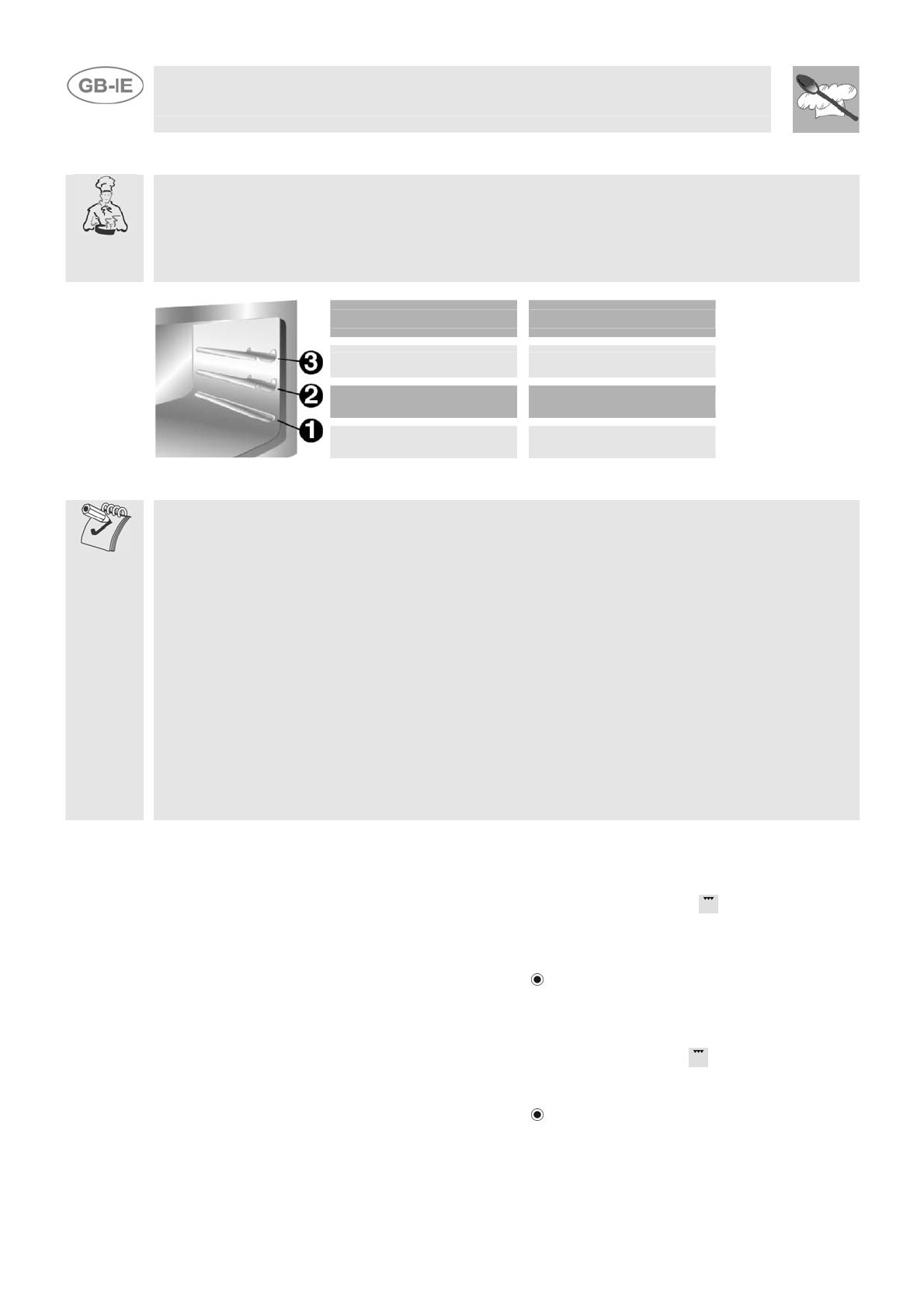
The food should be placed on the oven shelf which is positioned on one of the guides supplied with
the different ovens, following the instructions below:
FOOD GRILLE ON THE SHELF
Flat or thin meat
3
Rolled roast joints
2 – 3
Poultry
2 – 3
WARNINGS
Cooking procedures in this mode must never last more than 60 minutes.
In models with gas oven, the door must be half-open on the first catch during grilling and
grill-rotisserie cooking.
In models with electric oven, the door must be close during grilling and grill-rotisserie
cooking.
To avoid dangerous overheating when the oven or the grill is used, the glass cover must
always be up. The electric grill and the gas oven cannot be used at the same time.
During and after use the accessible parts of the oven may be very hot, and children must
always be kept at a distance.
During cooking with the rotisserie, one of the oven trays provided with the cooker should
be placed in the bottom of the oven, inserting it on the bottom runners, in order to collect
the grease and fats which may be formed.
During cooking, do not cover the bottom of the oven with aluminium or tin foil and do not
place pans or oven trays on it as this may damage the enamel coating. If you wish to use
greaseproof paper, place it so that it will not interfere with the hot air circulation inside
the oven.
When using the oven, remove all unused baking sheets and shelves from the interior.
7.5 Use of the gas grill
7.5.1 Manual lighting of the gas grill burner
Having opened the oven door, press the knob and turn it clockwise to the grill position, placing a
lit match to the burner on the roof of the oven.
Once the burner is lit, hold the knob down for about 10 seconds. If the burner does not stay lit after
this time, release the knob and wait for at least one minute before trying again. If the burner
accidentally goes out, turn the knob to the off position (
) and wait at least one minute before lighting
again.
7.5.2 Electric lighting of the gas grill burner
Having opened the oven door, press the knob and turn it clockwise to the grill
position.
Once the burner is lit, hold the knob down for about 10 seconds. If the burner has not come on by
this time, release the knob and wait for at least one minute before trying again. If the burner
accidentally goes out, turn the knob to the off position (
) and wait at least one minute before lighting
again.
During a power cut the burner can always be lit with a match.
Instruction for the user
19
7.6 Storage compartment
A storage compartment, accessible by pulling on the top edge
of the door, is located beneath the oven.
Never store flammable materials such as rags, paper or the
like. The compartment is intended only for holding the metal
accessories of the range.
Never open the storage compartment when the oven is on and still hot. The temperature inside may
be very high.
7.7 Upright (certain models only).
Some models have an additional storage compartment beside
the oven; this can be used to store the metal accessories
supplied with the cooker when they are not in use.
7.8 Removable basket (certain models only)
On some models, the compartment beside the oven houses a
removable basket with 2 shelves, which can be used to store
various objects.
The basket is not designed to take heavy loads. No more
than 3-3.5 kg should be placed on the shelves in order to
avoid the risk of tipping.
Instruction for the user
20
8 ELECTRONIC PROGRAMMER (ONLY ON EQUIPPED MODELS)
LIST OF FUNCTIONS
MINUTE-COUNTER KEY
COOKING TIME KEY
END-OF-COOKING KEY
DECREASE TIME KEY
INCREASE TIME KEY
8.1 Clock adjustment
When using the oven for the first time, or after a power failure, the display flashes regularly and
indicates
. Press the keys and at the same time the keys or : each single press
changes the time by 1 minute either up or down.
Before setting the programmer activate the desired function and temperature.
8.2 Semiautomatic cooking
Use this setting for automatic oven switch-off at the end of cooking time.
By pressing key
, the display lights up, showing ; keep the key pressed and at the same time,
press keys
or to set the cooking time.
Release key
to start the programmed cooking time count. The display will now show the right time
together with symbols A and
.
8.3 Automatic cooking
Use this setting to automatically start and stop the oven.
By pressing key
, the display lights up showing ; keep the key pressed and at the same time,
press keys or to set the cooking time.
By pressing key
the sum of the right time + cooking time will appear; keep the key pressed and at
the same time, press keys
or to regulate the end of cooking time. Release key to start the
programmed count and the display will show the right time together with symbols A and
.
After set-up, to see the cooking time remaining, press the key ; to see the end of cooking time
press the key . Set-up with incoherent values is logically prevented (e.g. the contrast between a
cooking time and a longer period will not be accepted by the programmer).
Instruction for the user
21
8.4 End of cooking
When cooking is over, the oven will automatically switch off and, at the same time, an intermittent
alarm will sound. After switching off the alarm, the display will once again show the right time
together with the symbol
, indicating that the oven has returned to manual operation mode.
8.5 Minute Counter
The programmer can also be used as a simple minute counter. By pressing key , the display
shows
; keep the key pressed and at the same time press keys or . On releasing the key
, programmed counting will begin and the display will show the current time and the symbol .
After set-up, to see the remaining time, press the key .
Use as a minute counter does not interrupt functioning of the oven at the end of the programmed
time.
8.6 Adjusting alarm volume
The acoustic alarm has 3 different volume settings.
To change the setting, press the
key at the end of the minute counter function with the acoustic
alarm in operation.
8.7 Switching off the alarm
The alarm switches off automatically after seven minutes. They can be manually de-activated by
pressing the keys
and together. To switch off the appliance, rotate all the knobs to
position 0.
8.8 Cancellation of set data
Once the programme has been set, keep the key of the function to be cancelled pressed, while at
the same time
is reached by means of variation keys or . Time cancellation will be
considered as end-of-cooking time by the programmer.
8.9 Changing the set data
The cooking data entered can be changed at any time by keeping the function key pressed and at
the same time adjusting the keys
or .
Instruction for the user
22
9 DIGITAL TIMER (CERTAIN MODELS ONLY)
This component allows an on-off beeper to be set to indicate the end of the cooking time. It is
therefore just a timer, with no programming functions.
LIST OF FUNCTIONS
TIME-SETTING BUTTON
VALUE DECREASE BUTTON
VALUE INCREASE BUTTON
9.1.1 Setting the time
When the oven is used for the first time, or after a power blackout, the display flashes on and off at
regular intervals showing
. Press the key and use the or keys to set the current
time.
9.1.2 Setting the timer
To set the timer, press the
key and keep it pressed until the required number of minutes is shown.
When the key is released, after 5 seconds the countdown will start; once this finishes, an
acoustic device will sound.
During the countdown the display will show the
symbol; pressing the key displays the current
time for 5 seconds.
9.1.3 Deactivating the acoustic device
The acoustic device stops sounding automatically after seven minutes. It can be deactivated in
manual mode by pressing the key.
9.1.4 Adjusting the volume of the acoustic device
The volume can be adjusted (3 settings) while it is in operation by pressing the key.
9.1.5 Modifying the data set
The timer data set can be modified at any moment by pressing the
or keys.
10 ANALOGUE CLOCK (ONLY ON EQUIPPED MODELS)
The mechanical timer is set by turning the knob clockwise.
The timer can be set from 0 to 55 minutes. At the end of the cooking time, an
alarm signal will be heard: to stop the alarm turn the external part of the knob to
position
.
The clock is set by pulling the knob and turning it clockwise.
  • Page 1 1
  • Page 2 2
  • Page 3 3
  • Page 4 4
  • Page 5 5
  • Page 6 6
  • Page 7 7
  • Page 8 8
  • Page 9 9
  • Page 10 10
  • Page 11 11
  • Page 12 12
  • Page 13 13
  • Page 14 14
  • Page 15 15
  • Page 16 16
  • Page 17 17
  • Page 18 18
  • Page 19 19
  • Page 20 20
  • Page 21 21
  • Page 22 22
  • Page 23 23
  • Page 24 24

Smeg SCB80GX User manual

Category
Kitchen & houseware accessories
Type
User manual
This manual is also suitable for

Smeg SCB80GX is a multifunctional gas-powered cooking appliance that combines a gas hob, oven, and grill, offering versatile cooking options for various culinary needs. It features four gas burners on the hob, including auxiliary, semi-rapid, rapid, and triple crown burners, providing a range of heating capacities for different cooking tasks. The oven, with a 66-liter capacity, allows for spacious cooking, while the grill function adds the ability to grill and brown food.

Ask a question and I''ll find the answer in the document

Finding information in a document is now easier with AI