Page is loading ...

1
NOTE: DIAGRAMS & ILLUSTRATIONS NOT TO SCALE.
INSTALLATION
INSTRUCTIONS
VENTED GAS FIREPLACE HEATERS - DIRECT VENT MODELS
P/N 700,020M REV. M 11/2004
RETAIN THESE INSTRUCTIONS
FOR FUTURE REFERENCE
FOR YOUR SAFETY: Do not store or use gasoline
or other flammable vapors or liquids in the vicin-
ity of this or any other appliance.
FOR YOUR SAFETY: What to do if you smell gas:
• DO NOT light any appliance.
• DO NOT touch any electrical switches.
• DO NOT use any phone in your building.
• Immediately call your gas supplier from a
neighbor’s phone. Follow your gas suppliers
instructions.
• If your gas supplier cannot be reached, call the
fire department.
Installation and service must be performed by a
qualified installer, service agency or the gas
supplier.
MODELS
POUR VOTRE SÉCURITÉ: Ne pas entreposer ni utiliser
d'essence ni d'autre vapeurs ou liquides inflammables
dans le voisinage de cet appareil ou de tout autre
appareil.
POUR VOTRE SÉCURITÉ: Que faire si vous sentez une
odeur de gaz:
• Ne pas tenter d'allumer d'appareil.
• Ne touchez à aucun interrupteur. Ne pas vous servir
des téléphones se trouvant dans le batiment où
vous vous trouvez.
• Evacuez la piéce, le bâtiment ou la zone.
• Appelez immédiatement votre fournisseur de gaz
depuis un voisin. Suivez les instructions du
fournisseur.
• Si vous ne pouvez rejoindre le fournisseur de gaz,
appelez le service dos incendies.
L'installation et service doit être exécuté par un qualifié
installeur, agence de service ou le fournisseur de gaz.
AVERTISSEMENT: ASSUREZ-VOUS DE BIEN SUIVRE
LES INSTRUCTIONS DONNÉ DANS CETTE NOTICE POUR
RÉDUIRE AU MINIMUM LE RISQUE D'INCENDIE OU
POUR ÉVITER TOUT DOMMAGE MATÉRIEL, TOUTE
BLESSURE OU LA MORT.
DIRECT VENT
DT-400 & DR-400
WARNING: IF THE INFORMATION IN THIS MANUAL
IS NOT FOLLOWED EXACTLY, A FIRE OR EXPLO-
SION MAY RESULT CAUSING PROPERTY DAM-
AGE, PERSONAL INJURY OR LOSS OF LIFE.
This appliance may be installed in an aftermar-
ket permanently located, manufactured home
(USA only) or mobile home, where not prohib-
ited by local codes. This appliance is only for
use with the type of gas indicated on the rating
plate. This appliance is not convertible for use
with other gases, unless a certified kit is used.
tlovilliM
sledoM
cinortcelE
sledoM
NMC004-TDNEC004-TD
PMC004-TDPEC004-TD
NMC004-RDNEC004-RD
PMC004-RDPEC004-RD
OTL Report No. 116-F-17-4

2
NOTE: DIAGRAMS & ILLUSTRATIONS NOT TO SCALE.
Figure 1
Installation must conform to local codes. In the
absence of local codes, installation must com-
ply with the current National Fuel Gas Code,
ANSI Z223.1. (In Canada, the current CAN-1
B149 installation code.) Electrical wiring must
comply with the National Electrical Code ANSI/
NFPA 70 - (latest edition). (In Canada, the
current CSA C22-1 Canadian Electrical Code.)
TABLE OF CONTENTS
Packaging ........................................ page 2
Introduction ..................................... page 2
General Information......................... page 2
Location .......................................... page 4
Appliance and Vent Clearances ....... page 4
Vent Termination Clearances ........... page 5
Typical Installation Sequence .......... page 5
Detailed Installation Steps ............... page 5
Step 1. Framing ............................. page 5
Step 2. Routing Gas Line ............... page 5
Fireplace Specifications ................... page 8
Step 3. Install the Venting System . page 8
Vertical Termination Systems .......... page 9
Vent Section Length Chart ............... page 9
Vertical Vent Tables and Figures...... page 12
Horizontal Termination System ........ page 14
Horizontal Vent Tables and Figures . page 16
Venting Using Flexible Vent Pipe ..... page 19
Step 4. Field Wiring ....................... page 20
Step 5. Optional Blower Kit Wiring page 20
Step 6. Connecting Gas Line.......... page 21
Step 7. Installing Logs ................... page 22
Step 8. Checking Unit Operation ..... page 22
Step 9. Installing Glass Door ......... page 22
Step 10. Burner Adjustments........... page 23
Step 11. Hood Installation ............... page 23
Finishing Requirements ................... page 23
Cold Climate Insulation.................... page 24
Installation Accessories ................... page 24
Gas Conversion Kits.................. page 26
TYPICAL INSTALLATION
DO NOT ATTEMPT TO ALTER OR MODIFY
THE CONSTRUCTION OF THE APPLIANCE OR
ITS COMPONENTS. ANY MODIFICATION OR
ALTERATION MAY VOID THE WARRANTY,
CERTIFICATION AND LISTINGS OF THIS UNIT.
PACKAGING
The assembled vented gas fireplace heater is
packaged with:
1 -one log set shrink-wrapped to the in-
side surface of the front glass enclo-
sure panel.
2 - one plastic bag containing the literature
package which consists of the homeowner's
care and operation instructions, installation
instructions and warranty; plastic bag lo-
cated in the control area.
3 - one vent restrictor for use in top vent appli-
cations; restrictor is taped to the inside of
the cabinet bottom.
4 - one hood wrapped in plastic taped to the
front of the top unit standoffs.
5 - one bag of glowing embers located in the
control area.
INTRODUCTION
These vented gas fireplace heaters are sealed
combustion, air circulating gas fireplaces de-
signed for residential applications. These appli-
ances must be installed with the Secure Vent™
and /or Secure Flex™ vent systems routed to
the outside atmosphere.
Millivolt appliances are designed to operate on
natural or propane gas. A millivolt gas control
valve with piezo ignition system provides safe,
efficient operation. External electrical power is
required to operate the optional blower if in-
stalled in these units.
GENERAL INFORMATION
Note: Installation and repair should be per-
formed by a qualified service person. The appli-
ance should be inspected annually by a quali-
fied professional service technician. More fre-
quent inspections and cleanings may be re-
quired due to excessive lint from carpeting,
bedding material, etc. It is imperative that the
control compartment, burners and circulating
air passage ways of the appliance be kept clean.
S'assurer que le brùleur et le compartiment des
commandes sont propres. Voir les instruc-
tions d'installation et d'utilisation qui
accompagnent l'appareil.
Provide adequate clearances around air open-
ings and adequate accessibility clearance for
service and proper operation. Never obstruct
the front openings of the appliance.
These appliances are designed to operate on
natural or propane gas only.
These millivolt and electronic versions of
these appliances are listed by Omni Test
Laboratories for installation in bedrooms
and mobile homes.
Electronic appliances are designed to operate
on natural or propane gas. An electronic inter-
mittent pilot ignition system provides safe,
efficient operation. External electrical power is
required to operate these units.
This installation manual will help you obtain a
safe, efficient, dependable installation for your
appliance and vent system.
Please read and understand these
instructions before beginning your
installation.

3
NOTE: DIAGRAMS & ILLUSTRATIONS NOT TO SCALE.
htiwsledoMtlovilliM
evlaVsaGdetaludoM-yllaunaM
saGenaporPdnalarutaN
srebmuNledoM)H/UTB(etartupnI
004-TD
004-RD
005,71ot005,31
.oNledoM
ezisecifirO
larutaNenaporP
004-TD
54#
840.0
hcni
004-RD
Table 1
Test gage connections are provided on the
front of the millivolt gas control valve (iden-
tified IN for the inlet and OUT for the mani-
fold side). A ¹⁄₈" NPT test gage connection
is provided at the inlet and outlet side of
the electronic gas control valve.
Minimum inlet gas pressure to these appli-
ances is 5.0 inches water column (1.24 kPa)
for natural gas and 11 inches water column
(2.74 kPa) for propane for the purpose of input
adjustment.
Maximum inlet gas supply pressure to these appli-
ances is 10.5 inches water column (2.61 kPa) for
natural gas and 13.0 inches water column (3.23
kPa) for propane.
The millivolt appliances are manually controlled
and feature a spark ignitor (piezo) that allows the
appliance's pilot gas to be lit without the use of
matches or batteries. This system provides
continued service in the event of a power outage.
Do not use these appliances if any part has been
under water. Immediately call a qualified, pro-
fessional service technician to inspect the ap-
pliance and to replace any parts of the control
system and any gas control which have been
under water.
Ne pas se servir de cet appareil s'il a été plongé
dans l'eau, complètement ou en partie. Appeler
un technicien qualifié pour inspecter l'appareil et
remplacer toute partie du système de contrôle et
toute commande qui ont été plongés dans l'eau.
Installations at Altitudes of 0 to 4500 ft.-
Units are tested and approved for elevations
of 0 to 4500 feet (0 to 1372 meters).
Installations at Altitudes above 4500 ft.-
For elevations above 4500 feet (1372
meters), install the unit according to the
regulations of the local authorities having
jurisdiction and, in the USA, the latest edition
of the National Fuel Gas Code (ANSI Z223.1)
or, in Canada, the latest edition of the
CAN1-B149.1 and .2 codes.
WARNING: FAILURE TO COMPLY WITH
THE INSTALLATION AND OPERATING IN-
STRUCTIONS PROVIDED IN THIS DOCU-
MENT WILL RESULT IN AN IMPROP-
ERLY INSTALLED AND OPERATING AP-
PLIANCE, VOIDING ITS WARRANTY. ANY
CHANGE TO THIS APPLIANCE AND/OR
ITS OPERATING CONTROLS IS DANGER-
OUS. IMPROPER INSTALLATION OR USE
OF THIS APPLIANCE CAN CAUSE SERI-
OUS INJURY OR DEATH FROM FIRE,
BURNS, EXPLOSION OR CARBON MON-
OXIDE POISONING.
These appliances must be isolated from the gas
supply piping system (by closing their individual
manual shut-off valve) during any pressure test-
ing of the gas supply piping system at test
pressures equal to or less than ¹⁄₂ psig (3.5 kPa).
These appliances and their individual shut-off
valves must be disconnected from the gas
supply piping system during any pressure test-
ing of that system at pressures in excess of ¹⁄₂
psig (3.5 kPa).
These appliances must not be connected to a
chimney or flue serving a separate solid fuel
burning appliance.
Carbon Monoxide Poisoning: Early signs of
carbon monoxide poisoning are similar to
the flu with headaches, dizziness and/or
nausea. If you have these signs, obtain fresh
air immediately. Turn off the gas supply to
the appliance and have it serviced by a
qualified professional, as it may not be op-
erating correctly.
WARNING: CHILDREN AND ADULTS
SHOULD BE ALERTED TO THE HAZARDS
OF HIGH SURFACE TEMPERATURES. USE
CAUTION AROUND THE APPLIANCE TO
AVOID BURNS OR CLOTHING IGNITION.
YOUNG CHILDREN SHOULD BE CARE-
FULLY SUPERVISED WHEN THEY ARE IN
THE SAME ROOM AS THE APPLIANCE.
WARNING: DO NOT PLACE CLOTHING
OR OTHER FLAMMABLE MATERIALS
ON OR NEAR THIS APPLIANCE.
AVERTISSEMENT: SURVEILLER LES
ENFANTS. GARDER LES VÊTEMENTS,
LES MEUBLES, L'ESSENCE OU AUTRES
LIQUIDES À VAPEUR INFLAMMABLES
À COTE DE L'APPAREIL.
Millivolt Models -
Millivolt models come standard with the
manually-modulated gas valve; flame ap-
pearance and heat output can be con-
trolled at the gas valve. Input of millivolt
models is shown in the following table:
All Models -
Maximum manifold pressure is 3.5 in. w.c.
(0.87 kPa) for natural gas and 10 in. w.c.
(2.49 kPa) for LP/Propane gas.
Table 1
shows the units' gas orifice size for
the elevations indicated.
Electronic Models -
Electronic models have a fixed rate gas valve.
Input of electronic models is shown in the
following table:
This appliance may be installed in an af-
termarket permanently located, manufac-
tured home (USA only) or mobile home,
where not prohibited by local codes. This
appliance is only for use with the type of
gas indicated on the rating plate. This ap-
pliance is not convertible for use with
other gases, unless a certified kit is used.
Cet appareil peut être installé dans un
maison préfabriquée (É.-U. seulement)
ou mobile déjà installée à demeure si
les réglements locaux le permettent. Cet
appareil doit être utilisé uniquement
avec les types de gaz indiqués sur la
plaque signalétique. Ne pas l'utiliser
avec d'autres gaz sauf si un kit de con-
version certifié est installé.
etaR-dexiFhtiwsledoMcinortcelE
evlaVsaG
saGenaporPdnalarutaN
srebmuNledoM)H/UTB(etartupnI
004-TD
004-RD
005,71

4
NOTE: DIAGRAMS & ILLUSTRATIONS NOT TO SCALE.
Figure 2
Figure 3
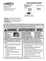
APPLIANCE AND VENT CLEARANCES
The appliance is approved with zero clearance
to combustible materials on all sides (as de-
tailed in
Table 2
), with the following excep-
tion: When the unit is installed with one side
flush with a wall, the wall on the other side of
the unit must not extend beyond the front edge
of the unit. In addition, when the unit is re-
cessed, the side walls surrounding the unit
must not extend beyond the front edge of the
unit. See
Figure 2
.
LOCATION
In selecting the location, the aesthetic and
functional use of the appliance are primary
concerns. However, vent system routing to
the exterior and access to the fuel supply are
also important. Consideration should be given
to traffic ways, furniture, draperies, etc., due
to elevated surface temperatures (
Figure 2
).
The location should also be free of electrical,
plumbing or other heating/air conditioning
ducting.
These direct vent appliances are uniquely suited
for installations requiring a utility shelf posi-
tioned directly above the fireplace. Utility
shelves like these are commonly used for
locating television sets and decorative plants.
To provide for the lowest possible shelf surface
use the alternate rear vent outlet with attached
venting routed in a way to minimize obstruc-
tions to the use of the space above the appli-
ance. Do not insulate the space between the
appliance and the area above it. See
Figure 3
.
The minimum height from the base of the
appliance to the underside of combustible ma-
terials used to construct a utility shelf in this
fashion is shown in the table in
Figure 3
.
The appliance should be mounted on a fully
supported base extending the full width and
depth of the unit. The appliance may be located
on or near conventional construction materi-
als. However, if installed on combustible ma-
terials, such as carpeting, vinyl tile, etc., a
metal or wood barrier covering the entire bot-
tom surface must be used.
Shelf Above Fireplace With Rear Venting
Do not insulate the
space between the
appliance and the
area above it.
Shelf Height
(
see table)
Shelf Height
(
see table)
Do not insulate the
space between the
appliance and the
area above it.
Shelf Above Fireplace With Top Venting
.oNledoM
)mm(sehcnithgieHflehS
woblEeergeD09enOhtiw-tneVpoTkcaBehttuOthgiartS-tneVraeR
tneVeruceSxelFeruceStneVeruceSxelFeruceS
004-TD 8/144)1211(8/754)5611(A/NA/N
004-RD A/NA/N4/133)548(4/133)548(
KCAB
)mm31(.ni2/1
srecaps)mm0(.ni0
SEDIS
)mm31(.ni2/1
srecaps)mm0(.ni0
SRECAPSPOT)mm0(.ni0
ROOLF)mm0(.ni0
mottoBmorF
ottinUfo
gnilieC
)mm6261(.ni46
TNEV*)mm4.52(.ni1
SECNARAELCECIVRES
TNORF)sretem9.0(.teeF3
(Rear Vent Application
HORIZONTAL VENT
without a chase)
HORIZONTAL VENT
(Rear Vent Application
With a chase)
HORIZONTAL VENT
(Top Vent
Application)
VERTICAL VENT
(Top Vent
Application)
(Rear Vent
VERTICAL VENT
Application)
APPLICATION
REAR VENT
APPLICATION
TOP VENT
APPLICATION
TOP VENT
REAR VENT
APPLICATION
TOP VENT
APPLICATION
RECESSED
INSTALLATION
TOP VENT
APPLICATION
APPLICATION
TOP VENT
APPLICATION
TOP VENT
Typical Locations

5
NOTE: DIAGRAMS & ILLUSTRATIONS NOT TO SCALE.
hctiPfooR
H
)teef(
21/6ottalF0.1
21/7ot21/6revO52.1
21/8ot21/7revO5.1
21/9ot21/8revO0.2
21/01ot21/9revO5.2
21/11ot21/01revO52.3
21/21ot21/11revO0.4
Right Side
Front Corner of
Fireplace Framing
6 ¹⁄₂"
(152 mm)
3"
(76 mm)
12
X
Roof Pitch is X/12
2 FT
MIN.
2 FT MIN.
Lowest
Discharge
Opening
H*
*H = MINIMUM HEIGHT FROM ROOF TO
LOWEST DISCHARGE OPENING OF VENT
TERMINATION HEIGHTS FOR VENTS ABOVE
FLAT OR SLOPED ROOFS
Horizontal Overhang
Vertical
Wall
Vent
Termination
Storm Collar
Concentric
Vent Pipe
Flashing
1 inch (25.4 mm) Minimum
Clearance to Combustibles
Figure 4
Figure 5 -
Side Elevation View
Figure 7
Horizontal Vent Termination Clearances
The horizontal vent termination must have a
minimum of 3" (76 mm) clearance to any
overhead combustible projection of 2 ¹⁄₂" (64
mm) or less. See
Figure 5.
For projections
exceeding 2 ¹⁄₂" (64 mm), see
Figure 5
. For
additional vent location restrictions refer to
Figure 7 on page 6
.
Terminate multiple vent terminations accord-
ing to the installation codes listed at the top of
this page.
Vertical Vent Termination Clearances
VENT TERMINATION CLEARANCES
These instructions should be used as a guide-
line and do not supersede local codes in any
way. Install vent according to local codes,
these instructions, the current National Fuel
Gas Code (ANSI-Z223.1) in the USA or the
current standards of CAN/CGA-B149.1 and -
B149.2 in Canada.
Terminate single vent caps relative to building
components according to
Figure 4
.
See
Figure 31
or 32 for the recess allowances,
into exterior walls, of the round and square
horizontal terminations.
Step 2. (page 5) Route gas supply line to
appliance location.
Step 3. (page 8) Install the vent system and
exterior termination.
Step 4. (page 20) Field Wiring
Millivolt Appliances – The operating control
switch is factory installed.
Step 5. (page 20) Install blower kit (optional
equipment).
Step 6. (page 21) Make connection to gas
supply.
Step 7. (page 22) Install the logs, vermicu-
lite and glowing embers.
Step 8. (page 22) Checkout appliance opera-
tion.
Step 9. (page 22) Install glass door frame
assembly.
Step 10. (page 23) Adjust burner to ensure
proper flame appearance.
Step 11. (page 23) Install the hoods.
Step 1. FRAMING
Frame these appliances as illustrated in
Fig-
ures 8 on page 7,
unless the appliance is to be
installed in a corner
.
See
Figure 9 on page 7
for corner framing installations. All framing
details must allow for a minimum clearance to
combustible framing members as shown in
Table 2 on page 4
.
If the appliance is to be elevated above floor level,
a solid continuous platform must be constructed.
Headers may be in direct contact with the appli-
ance top spacers but must not be supported by
them or notched to fit around them. All construc-
tion above the appliance must be self supporting,
DO NOT use the appliance for structural support.
Step 2. ROUTING GAS LINE
Route a ¹⁄₂" (13 mm) gas line along the inside of
the right side framing as shown in
Figure 7
.
Gas lines must be routed, constructed and
made of materials that are in strict accordance
with local codes and regulations.
All appliances are factory-equipped with a flex-
ible gas line connector and ¹⁄₂ inch shutoff
valve. (See step 6 on page 20).
TYPICAL INSTALLATION SEQUENCE
The typical sequence of installation follows,
however, each installation is unique resulting
in variations to those described.
See the page numbers references in the follow-
ing steps for detailed procedures.
Step 1. (page 5) Construct the appliance
framing. Position the appliance within the
framing and secure with nailing brackets.
DETAILED INSTALLATION STEPS
The appliance is shipped with all gas controls
and components installed and pre-wired. Re-
move the shipping carton, exposing the front
glass door. Remove the top panel. Remove
the cardboard from underneath the pressure
relief plates. Gently depress the outer top
corners of the access panel until the catches
"pop" the panel free, allowing it to swing out and
down to open. Open the two latches (located
under the firebox floor) securing the glass
door. Remove the door by tilting it outward at
the bottom and lifting it up. Set the door aside
protecting it from inadvertent damage.
See
Figure 50 on page 21.
Remove the two card-
board pad strips from between the firebox
subfloor and the firebox sides.
The fireplace should be secured to the side framing
members using the unit's nailing flanges - one top
and bottom on each side of the fireplace front. See
Figure 6.
Use 8d nails or their equivalent.
Figure 6
Note: The nailing flanges, combustible members
and screw heads located in areas directly adjacent
to the nailing flanges, are EXEMPT from the 1/2
”
clearance to combustible requirements for the
firebox outer wrapper. Combustible framing may be
in
direct contact with the nailing flanges and may
be located closer than 1/2
” from screw heads and
the firebox wrapper in areas adjacent to the nailing
flanges. Frame the opening to the exact dimensions
specified in the framing details of this manual.
Side
Framing
Unit Nailing Flange
(No clearance to
combustible
framing is required)
Left Side Front Corner of Fireplace Shown
(Right Side Requirements the Same)
Unit Being Secured By Its Nailing Flanges
To The Framing
3"
(76 mm)
12"
(305 mm)
Termination Kit
Combustible Projection
greater than 2¹⁄₂ inches in length
Horizontal Vent Termination Clearances
Combustible Projection
2¹⁄₂ inches or less in length
18"
(457 mm)
Ventilated
Soffit
Unventilated
Soffit

6
NOTE: DIAGRAMS & ILLUSTRATIONS NOT TO SCALE.
Figure 8
EXTERIOR HORIZONTAL VENT TERMINATION CLEARANCE REQUIREMENTS
*noitallatsnInaidanaC**noitallatsnISU
,hcrop,adnarev,edargevobaecnaraelC=A
.ynoclabro,kced
*)mc03(sehcni21**)mc03(sehcni21
ebyamtahtroodrowodniwotecnaraelC=B
.denepo
secnailpparof)mc51(ni6
)mc03(ni21,)Wk3(hutB000,01<
dna)Wk3(hutB000,01>secnailpparof
)mc19(sehcni63,)Wk03(hutB000,001<
*)Wk03(hutB000,001>secnailpparof
secnailpparof)mc51(ni6
)mc32(ni9,)Wk3(hutB000,01<
dna)Wk3(hutB000,01>secnailpparof
)mc03(sehcni21,)Wk51(hutB000,05<
**)Wk51(hutB000,05>secnailpparof
wodniwdesolcyltnenamrepotecnaraelC=C tneverpotdednemmocer)mm503("21
noitasnednocwodniw
tneverpotdednemmocer)mm922("9
noitasnednocwodniw
tiffosdetalitnevotecnaraelclacitreV=D
latnozirohanihtiwlanimretehtevobadetacol
retnecehtmorf)mm854(sehcni81foecnatsid
lanimretehtfoenil
)mm854("81)mm854("81
tiffosdetalitnevnuotecnaraelC=E)mm503("21)mm503("21
renrocedistuootecnaraelC=Fmuminim)mc7.21("5muminim)mc7.21("5
renrocedisniotecnaraelC=Gmuminim)mc2.51("6muminim)mc2.51("6
enilretnecfoedisnihcaeotecnaraelC=H
ylbmessarotaluger/retemevobadednetxe
teef51fothgiehanihtiw)mc19(teef3
*ylbmessarotaluger/retemehtevoba
teef51fothgiehanihtiw)mc19(teef3
**ylbmessarotaluger/retemehtevoba
teltuotnevrotalugerecivresotecnaraelC=I*)mc19(teef3**)mc19(teef3
telniylppusrialacinahcemnonotecnaraelC=J
ynaottelnirianoitsubmocehtrognidliubot
ecnailpparehto
secnailpparof)mc51(ni6
)mc03(ni21,)Wk3(hutB000,01<
dna)Wk3(hutB000,01>secnailpparof
)mc19(sehcni63,)Wk03(hutB000,001<
*)Wk03(hutB000,001>secnailpparof
secnailpparof)mc51(ni6
)mc32(ni9,)Wk3(hutB000,01<
dna)Wk3(hutB000,01>secnailpparof
)mc03(sehcni21,)Wk51(hutB000,05<
**)Wk51(hutB000,05>secnailpparof
telniylppusrialacinahcemaotecnaraelC=K*)m38.1(teef6 )m3(teef01nihtiwfievoba)mc19(teef3
**yllatnoziroh
devaproklawedisdevapevobaecnaraelC=L
ytreporpcilbupnodetacolyawevid
‡)m31.2(teef7 ‡)m31.2(teef7
rokced,hcrop,adnarevrednuecnaraelC=M
ynoclab
‡*)mc03(sehcni21 ‡)mc03(sehcni21
V
V
V
V
V
F
C
Fixed
Closed
Window
Operable
Window
B
B
A
B
H
M
I
= Vent Terminal = Area where Terminal is not Permitted
= Air Supply Inlet
X
V
D
V
3 ft.
3 ft.
A
A
A
= 9” in U.S.
= 12” in Canada
V
L
B
J
X
E
V
A
G
Inside
Corner Detail
*18”
Ventilated Soffit
Horizontal
Termination
Detail D
Exterior Wall
Center Line
of Termination
18”
Inside Corner
B
C
C
C
*
See Item D in the Text Below.
.edoCnoitallatsnIenaporPdnAsaGlanoitaN1.941B-ASCtnerrucehthtiwecnadroccanI*
.sedoCsaGleuFlanoitaN45APFN/1.322ZSISNAtnerucehthtiwecnadroccanI**
sevresdnasgnillewdylimafelgnisowtneewtebdetacolsihcihwyawevirddevaproklawedisaevobayltceridetanimrettonllahstnevA‡
.sgnillewdhtob
:roolfehthtaenebsedis2muminimanonepoyllufsiynoclabrokced,hcrop,adnarevfidettimrepylnO‡*

7
NOTE: DIAGRAMS & ILLUSTRATIONS NOT TO SCALE.
*34⁵⁄₁₆
(872)
Back wall of chase/enclosure (including any finishing materials)
a
8³⁄₁₆ (208)
b
Note-
Venting requirements for rear vent applications in corner installations -
- the round termination (SV4.5HTR) may not be used
- the horizontal vent length “a” to “b,” must not exceed 28 inches (711 mm)
*17³⁄₁₆
(437)
Inches
(millimeters)
*These dimensions occur when one 45
degree elbow is connected directly to the
appliance collar and the unit moved ¹⁄₂ in.
(13 mm) into the room. This ¹⁄₂ in.
movement is required to achieve a min. of
5 in (127 mm) in the F dimension.
*F = 5 in.
(127 mm)
*24¹⁄₄
(616)
33¹⁄₈
(841)
*48¹⁄₂
(1232)
CORNER FRAMING WITH SQUARE HORIZONTAL
TERMINATIONS (SV4.5HTSSL, SV4.5HTSS or SV4.5HTS)
SV4.5HTSS & SV4.5HTSSL
Termination
Framing should be constructed of
2x4 or larger lumber.
7 (178)
b
SV4.5HTS Termination
7
(178)
5¹⁄₈
12¹⁄₈
(308)
10¹⁄₂
(267)
VENT FRAMING -
TOP VENT WITH ONE
90° ELBOW
VENT FRAMING -
REAR VENT WITH
NO ELBOWS
Framing should be constructed of
2x4 or larger lumber.
Inches (mm)
(130)
5¹⁄₈
(130)
7
(308)
12¹⁄₈
(178)
*12⁷⁄₈ inches (327 mm) is the required
framing depth dimension when the finish
material (drywall) thickness is 1/2 in.
(13mm).
*12⁷⁄₈
(327)
33¹⁄₄
(845)
33¹⁄₄
(845)
16⁵⁄₈
(422)
37¹⁄₈
(943)
19⁵⁄₈
(498)
**FRAMING WITH SQUARE HORIZONTAL TERMINATIONS (SV4.5HTSSL, SV4.5HTSS or SV4.5HTS)
AND ROUND HORIZONTAL TERMINATION (SV4.5HTR)
** See the horizontal venting Figures 35
and 36 on page 16 for restrictions on the
use of the round termination (SV4.5HTR)
Figure 9
Figure 10
FIREPLACE FRAMING SPECIFICATIONS

8
NOTE: DIAGRAMS & ILLUSTRATIONS NOT TO SCALE.
21¹⁄₂
(546)
13
(330)
¹⁄₂
(13)
1⁵⁄₈
(42)
8¹¹⁄₃₂
(212)
3 (76)
Top View
NOTE - Eyebrow
hood shown as positioned
in louvered front model.
*CONCENTRIC FLUE
FLUE - 4¹⁄₂ (114)
COMBUSTION AIR - 7¹⁄₂ (190)
FRAMING
SPACERS
(Top and Sides
and Rear)
GAS INLET
(Either Side
and bottom)
Front View
3 (76)
(Louvered Front Model Shown)
**Rear vent models only
ELECTRICAL INLET
2³⁄₄ x 2 (70 x 51)
COVER PLATE with
KNOCKOUT)
Right Side View
*DR models have only a rear vent
*DT models have only a top vent
6¹³⁄₁₆
(173)
2³⁄₄
(70)
33¹⁄₈
(841)
30¹⁄₈
(765)
27¹⁄₂
(699)
17
(432)
**19⁵⁄₈
(498)
10³⁄₄
(273)
33¹⁄₈
(841)
Inches (millimeters)
1 (25)
1
(25)
VENT RESTRICTOR INSTALLATION
(TOP VENT)
In all venting applications using the top vent of
the appliance, a vent restrictor may be
needed. Install the vent restrictor in the top
vent of the appliance outlet.
RESTRICTOR
APPLIANCE TOP VENT OUTLET
If needed, install the restrictor orientated as
shown, either from inside or outside the unit,
in the inner fireplace collar.
INNER
FIREPLACE
COLLAR
Figure 11
Figure 12
Step 3. INSTALL THE VENT SYSTEM
General Information
These instructions should be used as a guide-
line and do not supersede local codes in any
way. Install vent according to local codes,
these instructions, the current National Fuel
Gas Code (ANSI-Z223.1) in the USA or the
current standards of CAN/CGA-B149.1 and -
B149.2 in Canada.
These fireplaces are designed, tested and
listed for operation and installation with,
and only with, Secure Vent™ (SV 4.5)
Direct Vent System Components, Secure
Flex™ Flexible Vent Components manu-
factured by Security Chimneys Interna-
tional. These approved vent system com-
ponents are labeled for identification.
FIREPLACE SPECIFICATIONS
DO NOT use any other manufacturer's
vent components with these appli-
ances. These fireplaces must be vented
directly to the outside.
The vent system may not service multiple
appliances, and must never be connected to a
flue serving a solid fuel burning appliance. The
vent pipe is tested to be run inside an enclos-
ing wall (such as a chase). There is no require-
ment for inspection openings in the enclosing
wall at any of the joints in the vent pipe.
Preparing the Appliance Top Vent Outlet in
All Venting Applications Using the Appliance
Top Vent Outlet
A vent restrictor may be needed with this
appliance. Install the vent restrictor (provided)
in the appliance top flue outlet as shown in
Figure 12
. It is held in place by friction, only.

9
NOTE: DIAGRAMS & ILLUSTRATIONS NOT TO SCALE.
TRAHCHTGNELNOITCESTNEV
lanimoN
htgneLnoitceS
)sehcni(
621426384
T
O
T
A
L
Q
T
Y
noitceSteN
)sehcni(htgneL
2/1-42/1-012/1-222/1-432/1-64
tneVfothgieHsnoitceStneVforebmuN
sehcnitf
5.4573.0100001
957.0200002
5.01578.0010001
5152.1110002
5.91526.12100
0
3
1257.1020002
5.22578.1001001
5.52521.2120003
5.13526.2030003
5.43578.2000101
5.73521.3111003
5.34526.3021003
5457.3002002
5.64578.3000011
5.94521.4102003
1552.4100012
5.55526.4012003
7557.4001102
6652.5022004
5.76526.5003003
9657.5000202
27 6103004
5.37521.6100203
5.97526.6010203
1857.6000112
095.7021014
5.19526.7002013
3957.7000022
69 8101204
5.79521.8100023
2015.8200024
5.301526.8000303
801 9100304
4115.9020024
71157.9105006
5.811578.9110305
6215.01001304
5.031578.01101305
53152.11006006
8315.11000404
5.931526.11000033
5.241578.11100405
TRAHCHTGNELNOITCESTNEV
noitceSlanimoN
)sehcni(htgneL
621426384
T
O
T
A
L
Q
T
Y
noitceSteN
)sehcni(htgneL
2/1-42/1-012/1-222/1-432/1-64
tneVfothgieHsnoitceStneVforebmuN
sehcnitf
44121100034
0515.21010034
5.451578.21110035
5.061573.31020035
5.271573.41000505
77157.41100506
38152.51010506
6815.51000044
5.091578.51100045
5.691573.61010045
5.502521.71011507
70252.71000606
5.112526.71100607
5.712521.81010607
5.922521.91001607
5.232573.91000055
73257.91100056
5.142521.02000707
6425.02100708
25212010708
46222001708
67232000808
97252.32000066
5.082573.32100809
5.382526.32100067
5.982521.42010067
5.103521.52001067
5.013578.52000909
5135.621009001
5.523521.72000077
0335.72100078
63382010078
54357.8200001001
5.943521.9210001011
27313000088
5.673573.13100089
5.973526.1300011011
5.814578.43000099
32452.531000901
56457.8300000101
With the appliance secured in framing, deter-
mine vent routing and identify the exterior
termination location. The following sections
describe vertical (roof) and horizontal (exterior
wall) vent applications. Refer to the section
relating to your installation. A list of approved
venting components is shown in the tables on
pages 24 and 25.
SV4.5CGV-1
Termination
SV4.5FA OR
SV4.5FB Flashing
AND SV4.5SC
STORM COLLAR
*SV4.5BF
Firestop/Spacer
SV4.5L6/12/24/36/48
Vent Sections
40' Max
(12.2 M)
1" (25.4 mm)
Minimum
Clearance to
Combustibles
*When using Secure Flex,
use Firestop/Spacer
SF4.5BF
Figure 13
VERTICAL TERMINATION SYSTEMS (ROOF)
Vertical (Straight) Installation
Select Venting System - Horizontal or Vertical
Figures 13, and Figures 23 through 27 on
pages 12 to 13
and their associated
Vertical Vent Tables illustrate the various ver-
tical venting configurations that are possible
for use with these appliances. Secure Vent
pipe applications are shown in these figures;
Secure Flex pipe may also be used. A Vertical
Vent Table summarizes each system’s mini-
mum and maximum vertical and horizontal
length values that can be used to design and
install the vent components in a variety of
applications. Both these vertical vent systems
terminate through the roof. The minimum
vent height above the roof and/or adjacent
walls is specified in ANSI Z223.1-(latest edi-
tion) (In Canada, the current CAN-1 B149
installation code) by major building codes.
Always consult your local codes for specific
requirements. A general guide to follow is the
Gas Vent Rule (refer to
Figure 4
on page 5).
Determine the number of straight vent sections
required. 4 ¹⁄₂" (114 mm), 10 ¹⁄₂" (267 mm), 22
¹⁄₂" (572 mm), 34 ¹⁄₂" (876 mm) and 46 ¹⁄₂" (1181
mm) net section lengths are available. Plan the
vent lengths so that a joint does not occur at the
intersection of ceiling or roof joists. Refer to
the Vent Section Length Chart.

10
NOTE: DIAGRAMS & ILLUSTRATIONS NOT TO SCALE.
10¹⁄₂” Min.
(267 mm)
10¹⁄₂” Min.
(267 mm)
First Vent
Component
Align the dimple (four places)
with the opening of the locking
incline channel on appliance
collar. Twist vent component
clockwise to engage and seal.
Locking
Incline Channel
Dimple
Appliance collar
Vent / Appliance Collar
Connection
Align the dimple (four places) of the
upper vent section with the opening of
the locking incline channel on the
lower vent section. Twist vent
component clockwise to engage and
seal until arrow and dimple align.
Locking
Incline Channel
Dimple
Arrow
Connected
Vent Sections
Vent / Vent Section
Connection
Arrow
Arrow
Figure 14
Figure 15
Figure 17
Figure 16
Vertical (Offset) Installation
Analyze the vent routing and determine the
quantities of vent sections and number of el-
bows required. Refer to Vertical Vent Figures
and Tables on page 12 and 13 to select the type
of vertical installation desired. Vent sections
are available in net lengths of 4 ¹⁄₂" (114 mm),
10 ¹⁄₂" (267 mm), 22 ¹⁄₂" (572 mm), 34 ¹⁄₂" (876
mm) and 46 ¹⁄₂" (1181 mm). Refer to the Vent
Section Length Chart on page 9 for an aid in
selecting length combinations. Elbows are avail-
able in 90° and 45° configurations. Refer to
Figure 18
for the SV4.5E45 and SV4.5E90
elbow dimensional specifications.
Where required, a telescopic vent section
(SV4.5LA) may be used to provide the installer
with an option in installing in tight and confined
spaces or where the vent run made up of fixed
length pieces develops a joint in a undesirable
location, or will not build up to the required
length. The SV4.5LA Telescopic Vent Section
has an effective length of from 1 ¹⁄₂" (38 mm) to
7 ¹⁄₂" (191 mm). The SV4.5LA is fitted with a
locking inclined channel end (identical to a
normal vent section component) and a plain
end with 3 pilot holes. Slip the plain end over the
locking channel end of a standard SV4.5 vent
component the required distance and secure
with three screws.
Maintain a minimum 1" (25 mm) clearance to
combustible materials for all vertical elements.
Clearances for all horizontal elements are 3"
(76 mm) on top, 1" (25 mm) on sides and 1"
(25 mm) on the bottom.
A. Frame ceiling opening - Use a plumb line
from the ceiling above the appliance to lo-
cate center of the vertical run. Cut and/or
frame an opening, 10¹⁄₂" x 10¹⁄₂" (267mm x
267mm) inside dimensions, about this cen-
ter mark
(Figure 14)
.
To attach a vent component to the appliance
collar, align the dimpled end over the collar,
adjusting the radial alignment until the four
locking dimples are aligned with the inlet of the
four inclined channels on the collar (
refer to
Figure 15
). Push the vent component against
the collar until it fully engages, then twist the
component clockwise, running the dimples
down and along the incline channels until they
seat at the end of the channels. The unitized
design of the Secure Vent components will
engage and seal both the inner and outer pipe
without the need for sealant or screws. If
desired, a #6 x ¹⁄₂" screw may be used at the
joint, but is not required as the pipe will se-
curely lock when twisted.
Note: An elbow may also be attached to the
appliance collar. Attach in the same manner as
you would a vent section.
C. Attach vent components to each other -
Other vent sections may be added to the pre-
viously installed section in accordance with
the requirements of the vertical vent figures
and tables.
B. Attach vent components to appliance -
Secure Vent SV4.5 direct vent system compo-
nents are unitized concentric pipe components
featuring positive twist lock connections (
see
Figure 15
).
To add another vent component to a length of
vent run, align the dimpled end over the inclined
channel end of the previously installed section,
adjusting the radial alignment until the four
locking dimples are aligned with the inlets of the
four incline channels of the previous section.
Push the vent component against the previous
section until it fully engages, then twist the
component clockwise running the dimples down
and along the incline channels until they seat at
the end of the channels.This seating position
is indicated by the alignment of the arrow and
dimple as shown in
Figure 16.
D. Install firestop/spacer at ceiling - Use a
SV4.5BF firestop/spacer at ceiling joists. If
there is living space above the ceiling level, the
firestop/spacer must be installed on the bot-
tom side of the ceiling. If attic space is above
the ceiling, the firestop/spacer must be in-
stalled on the top side of the joist. Route the
vent sections through the framed opening and
secure the firestop/spacer with 8d nails or
other appropriate fasteners at each corner.
Remember to maintain 1" (25 mm) clear-
ance to combustibles, framing members,
and attic or ceiling insulation when running
vertical chimney sections.
E. Support the vertical vent run sections -
Note - Proper venting support is very impor-
tant. The weight of the vent must not be sup-
ported by the firplace in any degree.
Support the vertical portion of the venting sys-
tem every 8 feet (2.4m) above the fireplace vent
outlet. One method of support is by utilizing
field provided support straps (conventional
plumber's tape). Secure the plumber's tape to
the framing members with nails or screws.
All of the appliances covered in this document
are fitted with collars having locking inclined
channels. The dimpled end of the vent compo-
nents fit over the appliance collar to create the
positive twist lock connection.
1 inch
(25.4 mm)
minimum
clearance to
combustibles
Support Straps
(Plumber’s tape)
8 feet (2.4 m)
Maximum
Blocking

11
NOTE: DIAGRAMS & ILLUSTRATIONS NOT TO SCALE.
Framing Dimensions for Roof
Pitch C D
0/12 10¹⁄₂ in. 10¹⁄₂ in.
(267 mm) (267 mm)
6/12 10¹⁄₂ in. 12 in.
(267 mm) (305 mm)
12/12 10¹⁄₂ in. 17 ³⁄₄ in.
(267 mm) (451 mm)
SV4.5E90
(90° Elbow)
8 ¹⁄₈"
(206 mm)
Swivel Joint
(360
°
swivel)
4 ¹³⁄₁₆"
(122 mm)
SV4.5E45
(45° Elbow)
Swivel Joint
(360
°
swivel)
C
D
Storm
Collar
Figure 19
Figure 20
Figure 22
Figure 21
Figure 18
K. Install the vertical termination - The final
step involves installation of the SV4.5CGV-1
Vertical Termination. Extend the vent sections to
the height as shown in the "Vertical vent termina-
tion section" on page 5. The SV4.5CGV-1 Verti-
cal Termination (
Figure 22
) installs in the exact
same fashion as any other Secure Vent section.
Align the termination over the end of the previ-
ously installed section, adjusting the radial align-
ment until the four locking dimples of the termi-
nation are aligned with the inlets of the four
incline channels of the last vent section. Push the
termination down until it fully engages, then twist
the termination clockwise running the dimples
down and along the incline channels until they
seat at the end of the channels.
I. Install the roof flashing - Extend the vent
sections through the roof structure. Install the
roof flashing over the vent section and posi-
tion such that the vent column rises vertically
(use carpenters level) (
Figure 20
). Nail along
perimeter to secure flashing or adjust roofing
to overlap the flashing edges at top and sides
only and trim where necessary. Seal the top
and both sides of the flashing with waterproof
caulking.
If the vent system extends more than 5' (1.5 m)
above the roof flashing, stabilizers may be
necessary. Additional screws may be used at
section joints for added stability. Guide wires
may be attached to the joint for additional
support on multiple joint configurations.
G. Continue installation of horizontal/inclined
sections - Continue with the installation of the
straight vent sections in horizontal/inclined run
as described in Step C. Install support straps
every 5' (1.52 m) along horizontal/inclined vent
runs using conventional plumber’s tape.
It is
very important that the horizontal/inclined
run be maintained in a straight (no dips) and
recommended to be in a slightly elevated
plane, in a direction away from the fireplace
of ¹⁄₄" rise per foot (20 mm per meter) which is
ideal, though rise per foot run ratios that are
smaller are acceptable all the way down to at or
near level. Use a carpenter’s level to measure
from a constant surface and adjust the support
straps as necessary.
It is important to maintain the required clear-
ances to combustibles: 1" (25 mm) at all sides
for all vertical runs; and 3" (76 mm) at the top,
1" (25 mm) at sides, and 1" (25 mm) at the
bottom for all horizontal/inclined runs.
H. Frame roof opening - Identify location for
vent at the roof. Cut and/or frame opening per
Roof Framing Chart and
Figure 19.
J. Install the storm collar - Install the storm
collar, supplied with the flashing, over the vent/
flashing joint. See
Figure 21.
Loosen the storm
collar screw. Slide collar down until it meets the
top of the flashing. Tighten the adjusting screw.
Apply non-combustible caulking or mastic
around the circumference of the joint to pro-
vide a water tight seal.
Loop the tape around the vent, securing the
ends of the tape to the framing. If desired,
sheet metal screws #6 x ¹⁄₂" length may be
used to secure the support straps to the vent
pipe. Refer to
Figure 17.
F. Change vent direction to horizontal/inclined
run - At transition from or to a horizontal/
inclined run, install the SV4.5E45 and SV4.5E90
elbows in the same manner as the straight vent
sections. The elbows feature a twist section to
allow them to be routed about the center axis of
their initial collar section to align with the re-
quired direction of the next vent run element.
Twist elbow sections in a clockwise direction
only so as to avoid the possibility of unlocking
any of the previously connected vent sec-
tions. See
Figure 18.

12
NOTE: DIAGRAMS & ILLUSTRATIONS NOT TO SCALE.
Figure 24
-
Rear Vent - ONE 90 DEGREE ELBOW
Figure 23
- Top Vent - STRAIGHT
Figure 25
-
Top Vent - TWO 90 DEGREE ELBOWS
VERTICAL VENT FIGURES/TABLES
Note: Secure Vent (rigid vent pipe) is shown
in the figures; Secure Flex (flexible vent pipe)
may also be used.
WARNING: UNDER NO CIRCUMSTANCES
MAY SEPARATE SECTIONS OF CONCEN-
TRIC FLEXIBLE VENT PIPE BE JOINED
TOGETHER.
Note: It is very important that the horizontal/
inclined run be maintained in a straight (no
dips) and recommended to be in a slightly
elevated plane, in a direction away from the
fireplace of
¹⁄₄
" rise per foot (20 mm per
meter) which is ideal, though rise per foot run
ratios that are smaller are acceptable all the
way down to at or near level.
Note: SV4.5BF (Secure Vent), SF4.5BF (Secure
Flex) firestop/spacer must be used anytime vent
pipe passes through a combustible floor or ceil-
ing. SV4.5HF (Secure Vent), SF4.5HF (Secure
Flex)firestop/spacer must be used anytime vent
pipe passes through a combustible wall.
Note: Two 45 degree elbows may be used in
place of one 90 degree elbow. The same rise to
run ratios, as shown in the venting figures for
90 elbows, must be followed if 45 degree
elbows are used.
AELBAT
VM MUMINI mumixaMH
teef)m(teef)m(
1)503.0(2)16.0(
2)16.0(4 )222.1(
3)419.0(6)68.1(
4)22.1(8)4.2(
.xaM)m4.21(teef04=H+V
.xaM)m4.2(teef8=H
V
H
*Ceiling
Firestop/Spacer
(SV4.5BF)
**Wall
Firestop/Spacer
(SV4.5HF)
*When using Secure Flex,
use Firestop/Spacer
SF4.5BF
**When using Secure
Flex, use Firestop/Spacer
SF4.5HF
BELBAT
VM
MUMINI
HmumixaM
teef)sretem(teef)sretem(
1)503.0(5)25.1(
2)016.0(01)1.3(
3)419.0(51)56.4(
4)22.1(02)2.6(
V+V
1
)m4.21(teef04=H+
.xaM
H.xaM)m2.6(teef02=
H
V
V1
*Ceiling
Firestop/Spacer
(SV4.5BF)
**Wall
Firestop/Spacer
(SV4.5HF)
**When using Secure
Flex, use Firestop/Spacer
SF4.5HF
*Ceiling
Firestop/Spacer
(SV4.5BF)
*When using Secure Flex,
use Firestop/Spacer
SF4.5BF
40 feet (12.2 meters)
Maximum
*Ceiling
Firestop/Spacer
(SV4.5BF)
*When using
Secure Flex, use
Firestop/Spacer
SF4.5BF

13
NOTE: DIAGRAMS & ILLUSTRATIONS NOT TO SCALE.
Figure 26
- Rear Vent - THREE ELBOWS
Figure 27 -
Top Vent - THREE ELBOWS
VERTICAL VENT FIGURES/TABLES
(continued)
EELBAT
VM
MUMINI
HH+
1
mumixaM
teef)m(teef)m(
1)503.0(5)25.1(
2)016.0(01)1.3(
3)419.0(51)56.4(
4)22.1(02)2.6(
H+H
1
.xaM)m2.6(teef02=
V+V
1
H+H+
1
.xaM)m4.21(teef04=
DELBAT
muminiMVmumixaMHH+H
1
mumixaM
teef)m(teef)m(teef)m(
1)503.0(2)016.0(5)25.1(
2)016.0(4)22.1(01)1.3(
3)419.0(6)68.1(51)56.4(
4)22.1(8)84.2(02)2.6(
V+V
1
H+H+
1
.xaM)m4.21(teef04=
.xaM)m84.2(teef8=H
H+H
1
.xaM)m2.6(teef02=
H1
V
V1
H
*Ceiling
Firestop/Spacer
(SV4.5BF)
**Wall
Firestop/Spacer
(SV4.5HF)
*Ceiling
Firestop/Spacer
(SV4.5BF)
A Vent Restrictor, as
shown in Figure 18,
page 10, must be used
in this application
*When using Secure Flex,
use Firestop/Spacer
SF4.5BF
**When using Secure
Flex, use Firestop/Spacer
SF4.5HF
V
H
1
H
V
1
*Ceiling
Firestop/Spacer
(SV4.5BF)
**Wall
Firestop/Spacer
(SV4.5HF)
*When using Secure Flex,
use Firestop/Spacer
SF4.5BF
**When using Secure
Flex, use Firestop/Spacer
SF4.5HF

14
NOTE: DIAGRAMS & ILLUSTRATIONS NOT TO SCALE.
Vertical
Rise
SV4.5E90
Elbow
Horizontal / Inclined Run
SV4.5HTSSL
Termination
Shown
*Ceiling
Firestop/Spacer
(SV4.5BF)
SV4.5L6/12/24/36/48
Vent Sections
Support Bracket Spacing
Every 5 ft (1.52 m)
See Figure 17 on page 10
for vertical vent section
support.
Support
Brackets
Building
Support
Framing
Ceiling
Fireplace
Exterior
Wall
Exterior
Wall
TYPICAL HORIZONTAL VENT INSTALLATION
Firestop/Spacer
SV4.5HTSSL
Termination
Shown
Fireplace
*When using Secure Flex
use Firestop/Spacer
(SF4.5BF)
Figure 28
Secure Vent SV4.5 direct vent system compo-
nents are unitized concentric pipe components
featuring positive twist lock connection, (
refer to
Figure 15
on page 10). All of the appliances
covered in this document are fitted with collars
having locking inclined channels. The dimpled
end of the vent components fit over the appliance
collar to create the positive twist lock connection.
A. Plan the vent run -
Analyze the vent routing and determine the
types and quantities of sections required
4 ¹⁄₂" (114 mm), 10 ¹⁄₂" (267 mm), 22 ¹⁄₂" (572
mm), 34 ¹⁄₂" (876 mm) and 46 ¹⁄₂" (1181 mm)
net section lengths are available. Make allow-
ances for elbows as indicated in
Figure 18 on
page 10
. Maintain a minimum 1" (25 mm)
clearance to combustibles on the vertical
sections. Clearances for the horizontal runs
are; 3" (76 mm) on top, 1" (25 mm) on sides,
and 1" (25 mm) at the bottom.
B. Frame exterior wall opening -
Locate the center of the vent outlet on the exterior wall
according to the dimensions shown in
Figure 9
on
page 7. Cut and/or frame an opening, 10¹⁄₂" x 12¹⁄₈"
(267 mm x 308mm) inside dimensions, about this
center.
H. Change vent direction - At transition from
or to a horizontal/inclined run, install the
SV4.5E45 and SV4.5E90 elbows in the same
manner as the straight vent sections. The
elbows feature a twist section to allow them
to be routed about the center axis of their
initial collar section to align with the required
direction of the next vent run element. Twist
elbow sections in a clockwise direction only
so as to avoid the possiblity of unlocking
any of the previously connected vent sec-
tions. See
Figure 18 on page 11
.
F. Install firestop/spacer at ceiling -
When using Secure Vent, use SV4.5BF fir-
estop/spacer at ceiling joists; when using Se-
cure Flex, use SF4.5BF firestop/spacer. If there
is living space above the ceiling level, the fir-
estop/ spacer must be installed on the bottom
side of the ceiling. If attic space is above the
ceiling, the firestop/ spacer must be installed
on the top side of the joist. Route the vent
sections through the framed opening and se-
cure the firestop/spacer with 8d nails or other
appropriate fasteners at each corner.
Note: An elbow may also be attached to the
appliance collar. Attach in the same manner as
you would a vent section.
Remember to maintain 1" (25 mm) clearance
to combustibles, framing members, and attic
or ceiling insulation when running vertical
chimney sections.
E. Attach vent components to each other -
Other vent sections may be added to the previ-
ously installed section in accordance with the
requirements of the vent tables. To add another
vent component to a length of vent run, align the
dimpled end of the component over the inclined
channel end of the previously installed section,
adjusting the radial alignment until the four
locking dimples are aligned with the inlets of the
four incline channels of the previous section.
Push the vent component against the previous
section until it fully engages, then twist the
component clockwise running the dimples down
and along the incline channels until they seat at
the end of the channels.This seating position is
indicated by the alignment of the arrow and
dimple as shown in
Figure 16 on page 10.
D. Attach vent components to appliance - To
attach a vent component to the appliance collar,
align the dimpled end over the collar, adjusting
the radial alignment until the four locking dimples
are aligned with the inlets of the four incline
channels on the collar (
refer to Figure 15
on
page 10). Push the vent component against the
collar until it fully engages, then twist the com-
ponent clockwise, running the dimples down
and along the incline channels until they seat at
the end of the channels. The unitized design of
the Secure Vent components will engage and
seal both the inner and outer pipe elements with
the same procedure.
I. Continue installation of horizontal/inclined
sections - Continue with the installation of the
straight vent sections in horizontal/inclined
run as described in Step E. Install support
straps every 5 ft. (1.52 m) along horizontal/
inclined vent runs using conventional plumber’s
tape. See
Figure 28.
It is very important that
the horizontal/inclined run be maintained in a
straight (no dips) and recommended to be in
a slightly elevated plane, in a direction away
from the fireplace of
¹⁄₄" rise per foot (20 mm
per meter) which is ideal, though rise per foot
run ratios that are smaller are acceptable all the
way down to at or near level. Use a carpenter’s
level to measure from a constant surface and
adjust the support straps as necessary.
Figures 28, and Figures 34 to 41 on pages 16 to
18
and their associated Horizontal Vent Table
illustrate the various horizontal venting configura-
tions that are possible for use with these appli-
ances. Secure Vent pipe applications are shown in
these figures; Secure Flex pipe may also be used.
A Horizontal Vent Table summarizes each system’s
minimum and maximum vertical and horizontal
length values that can be used to design and install
the vent components in a variety of applications.
Both of these horizontal vent systems terminate
through an outside wall. Building Codes limit or
prohibit terminating in specific areas. Refer to
Figure 8
on page 6 for location guidelines.
HORIZONTAL (OUTSIDE WALL)
TERMINATION SYSTEM
G. Support the vertical run sections -
On the vertical run, support the venting system
every 8 feet (2.4m) above the fireplace vent
outlet with field provided support straps
(Plumber's tape).
Attach the straps to the vent
pipe and secure to the framing members with
nails or screws.
See
Figure 17 on page 10.
C. Frame ceiling opening - If the vertical
route is to penetrate a ceiling, use plumb line
to locate the center above the appliance. Cut
and/or frame an opening, 10¹⁄₂" x 10¹⁄₂" (267
mm x 267 mm) inside dimensions, about this
center (refer to
Figure 14
on page 10 ).
J. Assemble vent run to exterior wall - If not
previously measured, locate the center of the
vent at the exterior wall. Prepare an opening as
described in Step B
When using square (SV4.5 HTS), short square
(SV4.5 HTSS) or round (SV4.5HTR) horizon-
tal termination -
Assemble the vent system to point where the
terminus of the last section is within 6 in. (152
mm) to 10¹⁄₄ in. (260 mm) inboard of the
exterior surface to which the termination is to
be attached, see
Figure 31 on page 15
.
Sealant and securing screws are not required.
It is important to maintain the required clear-
ances to combustibles: 1" (25 mm) at all sides
for all vertical runs; and 3" (76 mm) at the top,
1" (25 mm) at sides, and 1" (25 mm) at the
bottom for all horizontal/inclined runs.

15
NOTE: DIAGRAMS & ILLUSTRATIONS NOT TO SCALE.
*Firestop/Spacer (SV4.5HF) shown
on the exterior side of the wall. It
may also be installed on the
interior side.
SV4.5 HTSS
Termination
Shown.
10¹⁄₂"
(267 mm)
7"
(178)
5¹⁄₈"
(130 mm)
12¹⁄₈"
(308 mm)
Note: Centerline of Vent
Piping is NOT the Same as
the Centerline of the
Framed Opening.
6 to 48 inch Vent Section,
Telescopic vent section,
Elbow or Appliance Collar
See Figure 9 on page
7 for Min. Distance to
Base of Appliance.
Base of Appliance
3"
(76 mm)
1"
(25.4 mm)
*Note - Firestop/Spacer integral
with round termination
(SV4.5HTR)
See Venting Figures for Use
Restrictions on the Horizontal
Round Termination (SV4.5HTR).
Adapter
SV4.5RCH
*Note - When using Secure Flex
use Firestop/Spacer SF4.5HF
*Firestop/Spacer (SV4.5HF) shown
on the exterior side of the wall. It
may also be installed on the
interior side.
SV4.5 HTSSL
Termination
10¹⁄₂"
(267 mm)
7"
(178)
5¹⁄₈"
(130 mm)
12¹⁄₈"
(308 mm)
Note: Centerline of Vent Piping is
NOT the Same as the Centerline of
the Framed Opening.
6 to 48 inch Vent Section,
Elbow or Appliance Collar
See Figure 9 on page 7
for Min. Distance to
Base of Appliance.
Base of Appliance
3"
(76 mm)
1"
(25.4 mm)
*When using Secure Flex, use
Firestop/Spacer (SF4.5HF)
1¹⁄₄" Maximum Recess of Square
Termination into Exterior Finishing
Material. Round Termination may
not be recessed at all.
Exterior Surface of Framing
6 in. to 10¹⁄₄ in.
(152 mm to 260 mm)
Exterior Surface of Siding
Minimum wall thickness
*6 in. (152 mm)
Interior Surface of Finished Wall
Maximum wall thickness
10¹⁄₄ in. (260 mm)
Maximum Extent of
Vent Run Sections
Relative to Exterior
Surface of Framing
Last Vent Section. Use
Telescopic Vent Section
(SV4.5LA), If Necessary
Adapter
SV4.5RCH
SV4.5HTSS Short
Square Termination
Shown
*Note - Firestop/Spacer
(SV4.5HF) required, but
not shown for clarity.
*Cut termination collar
for wall thicknesses
less than 6 in. (152 mm).
Siding
Stucco
SV4.5HTSS Short Square
Termination Shown
*When using Secure Flex, use
Firestop/Spacer SF4.5HF
Siding
Stucco
1¹⁄₄" Maximum Recess of
Square Termination into
Exterior Finishing Material
Exterior Surface of Framing
Exterior Surface of Siding
Minimum wall thickness
*10³⁄₄ in. (273 mm)
Interior Surface of
Finished Wall
Maximum wall thickness
20 in. (508 mm)
Maximum Extent of
Vent Run Sections
Relative to Exterior
Surface of Framing
Last Vent Section
SV4.5HTSSL Long
Square Termination
*When using Secure Flex, use
Firestop/Spacer SF4.5HF.
Termination Securing
Screw
SV4.5HTSSL Long
Square Termination
*Cut termination collar
for wall thicknesses
less than 10³⁄₄ in. (273 mm).
10³⁄₄ to 20 in.
(273 to 508 mm)
*Note - Firestop/Spacer
(SV4.5HF) required, but not
shown for clarity.
Figure 32
Figure 30
Installing Long Square HorizontalTermination (SV4.5HTSSL)
Figure 29
Figure 31
If the terminus of the last section is not within
this distance, use the telescopic vent section
SV4.5LA, as the last vent section. For wall
thicknesses greater than that shown in
Figure
31
, refer to
table 3 on page 16
. This table lists
the additional venting components needed (in
addition to the termination and adapter) for a
particular range of wall thicknesses.
Installing Square HorizontalTermination (SV4.5HTS) Short Square Horizontal
Termination (SV4.5HTSS) Round Horizontal Termination (SV4.5HTR)
Connecting/Recessing
Square (SV4.5HTS)
Short Square (SV4.5HTSS)
or Round (SV4.5HTR)
Horizontal Termination
Connecting/Recessing
Long Square Horizontal
Termination (SV4.5HTSSL)
L. Install Firestop/Spacer at exterior wall -
When using either of the square terminations,
install SV4.5HF (Secure Vent), or SF4.5HF
(Secure Flex) firestop/spacer over the opening
at the exterior side of the framing, long side up,
with the 3 inch spacer clearance at the top as
shown in
Figure 29 or 30
, and nail into place.
(The Firestop/Spacer may be installed over the
opening at the interior side of the framing.)
When using the round termination, a separate
firestop/spacer is not required since this termi-
nation has integral spacers which provide the
same function as a separate firestop/spacer.
K. When using square (SV4.5HTS) or short
square (SV4.5 HTSS) horizontal termination
- attach termination adapter -
Attach the adapter (adapter - SV4.5RCH - pro-
vided with the termination) to the vent section or
telescoping vent section), elbow or appliance
collar as shown in
Figure 29
in the same manner
as any SV4.5 vent component (refer to Step E).
When using long square (SV4.5HTSSL)
horizontal termination -
Assemble the vent system to point where the
terminus of the last section is within 0 in. (0
mm) to 9³⁄₄ in. (248 mm) inboard of the
exterior surface to which the termination is to
be attached, see
Figure 32
.

16
NOTE: DIAGRAMS & ILLUSTRATIONS NOT TO SCALE.
SFHRK Snorkel Cap –The snorkel cap is de-
signed to be fitted into a basement window
box. The SFHRK cap is for use with flex vent
The vertical distance between the inlet and
outlet of the cap is 28 in. (711 mm). pipe.
*Note: See Figure 35 for wall thickness range reductions when using
SV4.5HTS and SV4.5HTSS terminations.
Figure 35
-
Figure 34
-
See
Table 3
as an aid in venting component selection for a particular
range of exterior wall thicknesses.
HORIZONTAL VENT FIGURES/TABLES
Note: Two 45 degree elbows may be used in place of one 90 degree elbow. The same
rise to run ratios, as shown in the venting figures for 90 elbows, must be followed if
45 degree elbows are used.
Note: It is very important that the horizontal/inclined run be maintained
in a straight (no dips) and recommended to be in a slightly elevated
plane, in a direction away from the fireplace of
¹⁄₄
" rise per foot (20 mm
per meter) which is ideal, though rise per foot run ratios that are smaller are
acceptable all the way down to at or near level.
The round horizontal termination (SV4.5HTR) may not be used.
WARNING: UNDER NO CIRCUMSTANCES MAY SEPARATE SECTIONS
OF CONCENTRIC FLEXIBLE VENT PIPE BE JOINED TOGETHER.
The round horizontal termination (SV4.5HTR) may not be used.
Note: Secure Vent components (rigid vent pipe and terminal) are shown in
the figures; Secure Flex components (flexible vent pipe and terminal) may also
be used.
Rear Vent - NO ELBOWS - with SV4.5HTS SQUARE OR
SV4.5HTSS SHORT SQUARE TERMINATION
Rear Vent - NO ELBOWS - with SV4.5HTSSL
LONG SQUARE TERMINATION
Note: SV4.5BF (Secure Vent), SF4.5BF (Secure Flex) firestop/spacer must be
used anytime vent pipe passes through a combustible floor or ceiling. SV4.5HF
(Secure Vent), SF4.5HF (Secure Flex) firestop/spacer must be used anytime
vent pipe passes through a combustible wall.
roiretxEsuoiraVrofderiuqeRstnenopmoCgnitneV-3ELBAT
-stiKnoitanimreTesehTfoynAgnisUnehW,sessenkcihTllaW
noitanimreTerauqSllamS)STH5.4VS(noitanimreTerauqS
)RTH5.4VS(noitanimreTdnuoR)SSTH5.4VS(
stnenopmoCgnitneV
deriuqeR
sessenkcihTllaWroiretxE
mm(sehcni )
ylnOtiKnoitanimreT64/101ot)062ot251(
tnev.ni6dnatiKnoitanimreT
)6L5.4VS(noitces
)573ot062(4/341ot4/101
tnev.ni21dnatiKnoitanimreT
)21L5.4VS(noitces
)725*ot524(4/302*ot4/361
cipocseleTdnatiKnoitanimreT
.ni6dna)AL5.4VS(noitces
)6L5.4VS(noitcestnev
)255*ot892(4/312*ot4/311
*Wall Firestop/Spacer
(SV4.5HF)
28 in. (711 mm)
Maximum
Note - In applications where the wall thickness is less than 6 inches
(152 mm), field shortening of the termination collar may be required.
SV4.5HTSS Termination Shown
20 in. (508 mm)
Maximum
*When using Secure Flex,
use Firestop/Spacer
(SF4.5HF)
*Wall Firestop/Spacer
(SV4.5HF)
28 in. (711 mm)
Maximum.
Note - It may be necessary to cut the termination collar
in some applications.
10³⁄₄ to 20 in.
(273 to 508 mm)
12 in. Vent Section
(SV4.5L12)
*When using Secure flex,
use Firestop/Spacer
SF4.5HF)
Do Not recess the SV4.5HTR round termina-
tion at all.
See Horizontal Venting
Figures and Tables for
Use Restrictions
SV4.5HTR Horizontal
Round Termination
Figure 33
3. Install the round termination (SV4.5HTR)
– See
Figure 33
for an illustration of the round
termination. For the last step, from outside the
exterior wall, slide the collars of the termina-
tion onto the adapter (same as shown in
Fig-
ure 31
for the SV4.5HTSS short square termi-
nation) until the termination seats against the
exterior wall surface to which it will be at-
tached. Orient the housing of the termination
with the arrow pointed upwards. Secure the
termination to the exterior wall.
M. Install the desired termination - See the
horizontal venting figures for application re-
strictions on the round termination (SV4.5HTR).
1. Install the square (SV4.5HTS) or short square
termination (SV4.5HTSS) - For the last step ,
from outside the exterior wall, slide the collars of
the termination into the adapter (see
Figure 31
)
until the termination seats against the exterior wall
surface to which it will be attached. Orient the
housing of the termination with the arrow pointed
upwards. Secure the termination to the exterior
wall. The horizontal termination must not be
recessed into the exterior wall or siding by more
than the 1 ¹⁄₄" (32 mm) as shown in
Figure 31
.
Orient the housing of the termination with the
arrow pointed upwards. Secure the termina-
tion to the exterior wall. The horizontal termi-
nation must not be recessed into the exterior
wall or siding by more than the 1 ¹⁄₄" (32 mm)
as shown in
Figure 32
.
The SV4.5HTR Round Termination may not
be used when the appliance is vented di-
rectly out the wall from the rear as shown in
Figures 34 and 35
.
2. Install the long square termination
(SV4.5HTSSL) - For the last step , from outside
the exterior wall, slide the collars of the termi-
nation onto the last vent section (see
Figure 32
)
until the termination seats against the exterior
wall surface to which it will be attached.

17
NOTE: DIAGRAMS & ILLUSTRATIONS NOT TO SCALE.
Figure 37
-
Top Vent - ONE 90 DEGREE ELBOW -
ELBOW CONNECTION NOT DIRECTLY AT APPLIANCE
Figure 38
-
Rear Vent - TWO 90 DEGREE ELBOWS
Figure 36
-
Top Vent - ONE 90 DEGREE ELBOW - ELBOW CONNECTION AT APPLIANCE
Refer to
Table 3 on page 16
for an aid in venting component selection for a
particular range of exterior wall thicknesses when using the square (SV4.5HTS),
small square (SV4.5HTSS) or the round (SV4.5HTR) termination .
Refer to
Table 3 on page 16
for an aid in venting component selection
for a particular range of exterior wall thicknesses when using the
square (SV4.5HTS), small square (SV4.5HTSS) or the round
(SV4.5HTR) termination .
Refer to
Table 3 on page 16
for an aid in venting component selection for a
particular range of exterior wall thicknesses when using the square (SV4.5HTS),
small square (SV4.5HTSS) or the round (SV4.5HTR) termination .
HORIZONTAL VENT FIGURES/TABLES (CONTINUED)
Short Square Termination (SV4.5HTSS) shown;
Long Square Termination (SV4.5HTSSL) may also be used;
Square Termination (SV4.5HTS) may also be used
Round Termination (SV4.5HTR) may also be used.
Short Square Termination (SV4.5HTSS) shown;
Long Square Termination (SV4.5HTSSL) may also be used;
Square Termination (SV4.5HTS) may also be used
Round Termination (SV4.5HTR) may also be used.
Short Square Termination (SV4.5HTSS) shown;
Long Square Termination (SV4.5HTSSL) may also be used;
Square Termination (SV4.5HTS) may also be used
Round Termination (SV4.5HTR) may also be used.
ELBATF
wobleeerged09en0=V
.xaM)m419.0(teef3=H
ELBATG
muminiMVmumixaMH
teef)m(teef)m(
1)503.0(5)25.1(
2)16.0(01)1.3(
3)419.0(51)56.4(
4)22.1(02)2.6(
.xaM)m4.21(teef04=H+V
.xaM)m2.6(teef02=H
HELBAT
muminiMVmumixaMHH+H
1
mumixaM
teef)m(teef)m(teef)m(
1)503.0(2)016.0(5)25.1(
2)016.0(4)22.1(01)1.3(
3)419.0(6)68.1(51)56.4(
4)22.1(8)84.2(02)2.6(
H+H+V
1
.xaM)m4.21(teef04=
.xaM)m84.2(teef8=H
H+H
1
.xaM)m2.6(teef02=
H
*Wall Firestop/Spacer
(SV4.5HF)
V
*When using Secure Flex, use Wall Firestop/Spacer SV4.5HF.
H
V
*Wall Firestop/Spacer
(SV4.5HF)
**Ceiling Firestop/Spacer
(SV4.5BF)
*When using Secure Flex,
use Wall Firestop/Spacer
SF4.5HF.
**When using Secure Flex, use Ceiling
Firestop/Spacer SF4.5BF.
H
1
V
H
*Wall
Firestop/Spacer
(SV4.5HF)
**Ceiling
Firestop/Spacer
(SV4.5BF)
*Wall
Firestop/Spacer
(SV4.5HF)
*When using Secure
Flex, use Wall
Firestop/Spacer
SF4.5HF.
**When using Secure
Flex, use Ceiling
Firestop/Spacer
SF4.5BF.

18
NOTE: DIAGRAMS & ILLUSTRATIONS NOT TO SCALE.
Refer to
Table 3 on page 16
for an aid in venting component selection for a
particular range of exterior wall thicknesses when using the square (SV4.5HTS),
small square (SV4.5HTSS) or the round (SV4.5HTR) termination .
Figure 41
-
Top Vent - THREE 90 DEGREE ELBOWS
Figure 40
- Rear Vent - THREE 90 DEGREE ELBOWS
Figure 39
-
Top Vent - TWO 90 DEGREE ELBOWS
Refer to
Table 3 on page 16
for an aid in venting component selection for a particular range of exterior
wall thicknesses when using the square (SV4.5HTS), small square (SV4.5HTSS) or the round (SV4.5HTR)
termination .
Refer to
Table 3 on page 16
for an aid in venting component selection for a
particular range of exterior wall thicknesses when using the square (SV4.5HTS),
small square (SV4.5HTSS) or the round (SV4.5HTR) termination .
HORIZONTAL VENT FIGURES/TABLE (CONTINUED)
Short Square Termination (SV4.5HTSS) shown;
Long Square Termination (SV4.5HTSSL) may also be used;
Square Termination (SV4.5HTS) may also be used
Round Termination (SV4.5HTR) may also be used.
Short Square Termination (SV4.5HTSS) shown;
Long Square Termination (SV4.5HTSSL) may also be used;
Square Termination (SV4.5HTS) may also be used
Round Termination (SV4.5HTR) may also be used.
Short Square Termination (SV4.5HTSS) shown;
Long Square Termination (SV4.5HTSSL) may also be used;
Square Termination (SV4.5HTS) may also be used
Round Termination (SV4.5HTR) may also be used.
JELBAT
VM MUMINI H+H
1
mumixaM
teef)m(teef)m(
1)503.0(5)25.1(
2)016.0(01)1.3(
3)419.0(51)56.4(
4)22.1(02)2.6(
H+H+V
1
.xaM)m4.21(teef04=
H+H
1
.xaM)m2.6(teef02=
V
H
H
1
*Wall Firestop/Spacer
(SV4.5HF)
*Wall Firestop/Spacer
(SV4.5HF)
**Ceiling
Firestop/Spacer
(SV4.5BF)
*When using Secure Flex,
use Wall Firestop/Spacer
SF4.5HF.
**When using Secure
Flex, use Ceiling
Firestop/Spacer
SF4.5BF.
KELBAT
muminiMVmumixaMH
H+H
1
H+
2
mumixaM
teef)m(teef)m(teef)m(
1)503.0(2)016.0(5)25.1(
2)016.0(4)22.1(01)1.3(
3)419.0(6)68.1(51)56.4(
4)22.1(8)84.2(02)2.6(
H+H+V
1
H+
2
.xaM)m4.21(teef04=
.xaM)m84.2(teef8=H
H+H
1
H+
2
.xaM)m2.6(teef02=
V
H
**Ceiling Firestop/Spacer
(SV4.5BF)
*Wall Firestop/Spacer
(SV4.5HF)
*When using Secure Flex,
use Wall Firestop/Spacer
SF4.5HF.
**When using Secure Flex,
use Ceiling Firestop/Spacer
SF4.5BF.
H
2
H
1
LELBAT
VM MUMINI HmumixaM
teef)m(teef)m(
1)503.0(5)25.1(
2)016.0(01)1.3(
3)419.0(51)56.4(
4)22.1(02)2.6(
H+H
1
.xaM)m2.6(teef02=
V+V
1
H+H+
1
.xaM)m4.21(teef04=
V
H
H
1
V
1
*Wall Firestop/spacer
(SV4.5HF)
**Ceiling Firestop/spacer
(SV4.5BF)
*Wall Firestop/spacer
(SV4.5HF)
**When using Secure flex,
use Ceiling Firestop/spacer
SF4.5BF.
*When using Secure Flex,
use Wall Firestop/spacer
SF4.5HF.

19
NOTE: DIAGRAMS & ILLUSTRATIONS NOT TO SCALE.
D. Install Firestop/Spacers at ceilings and walls -
When Secure Flex penetrates a wall or ceiling,
a firestop/spacer is required: use the SF4.5 BF
firestop/spacer for ceilings and the SF4.5 HF
firestop/spacer for walls. See the appropriate
sections and figures shown throughout the
venting section for their installation requirments.
E. Attach Flex Vent to Termination -
Secure Flex components can be purchased
separately and attached to bulk lengths of
Secure Flex flexible tubing cut to size at the
job site. Secure the flexible vent to the Secure
Flex terminations in the same manner (see
Figure 42)
as it was attached to the adapter.
Note:
Secure Flex
vent must be attached to
Secure Flex
terminations only. DO NOT
substitute
Secure Vent
terminations or the
Secure Vent
adapter for
Secure Flex
compo-
nents. The collars of
Secure Flex
termina-
tions and adapters have a different circum-
ference than that used with the
Secure Vent
pipe. Additionally,
Secure Flex
components
have an extended length center tube for use
in attaching the flexible vent.
GEAR
CLAMPS
Adapter
(SV4.5RF)
Apply ONLY MIL-PAC BLACK HIGH
TEMPERATURE SEALANT (Catalog No.
10K81) to the outside surface of both
collars of the adapter (be especially
careful to fill the grooves of the outer
collar to be covered by the flexible
pipe) and slide flexible pipe over
inner and outer adapter collars.
NOTE: OUTER PIPE IS PULLED AWAY TO
SHOW THE DETAIL OF THE INNER PIPE
FLEX VENT
1³⁄₄ in. (44 mm)
Flexible Pipe and
Adapter Outer
Collar Overlap
1³⁄₄ in. (44 mm)
Flexible Pipe and
Adapter Inner
Collar Overlap
SECURING SCREW
(3 PLACES EQUIDISTANT
JUST BELOW GEAR CLAMP)
Attach Adapter to Appliance
Collar, or Secure Vent Sections
SECURING SCREW
(3 PLACES EQUIDISTANT
JUST BELOW GEAR CLAMP)
5" (127 mm)
Radius Minimum
SF-12 or SF-18 Flexible Vent Section
Figure 43
Figure 42
VERTICAL OR HORIZONTAL VENTING USING
SECURE FLEX
KITS AND COMPONENTS
Secure Flex venting kits and components may
be used in any venting application where rigid
Secure Vent (SV4.5) direct vent components
can be used. All restrictions, clearances and
allowances that pertain to the rigid piping apply
to the flexible venting.
Secure Flex
kits may
not be modified; also, under no circumstances
may separate sections of flex pipe be joined
together. Secure Flex kits may be added to the
end of a vent run made up of rigid Secure Vent
(SV4.5) vent sections provided that doing so
does not violate any of the venting length,
height, routing, horizontal to vertical ratio re-
quirements or clearance considerations de-
tailed in this manual.
Secure Flex kits come with an included adapter
that can be fitted to the appliance collar or the
inclined channel end of the last Secure Vent
(SV4.5) vent section in a rigid system in the
exact same fashion as any other Secure Vent
section. Align the dimpled end of the adapter
over the previously installed section or appli-
ance collar, adjusting the radial alignment until
the four locking dimples of the adapter are
aligned with the inlets of the four incline chan-
nels of the last vent section or collar. Push on
the adapter until it fully engages, then twist the
adapter clockwise running the dimples down
and along the incline channels until they seat at
the end of the channels.
Attach the flexible vent to the adapter as
follows (see also
Figure 42):
A. Install the Inner Flex Pipe -
1. Install the small gear clamp loosely around
the inner flexible vent pipe, push it back out of
the way.
2. Apply a bead of Mill-Pac Black (700°F)
high temperature sealant - Catalog No.
10K81) to the inner adapter collar, approxi-
mately ¹⁄₂ inch from the end.
3. Pull and extend the inner flexible vent pipe.
4. Slide the inner flex pipe over the adapter
collar. Ensure the flexible vent pipe completely
engages the adapter collar to a distance of 1³⁄₄
inches from the end, and that it is free from
damage or tears.
5. Slide the gear clamp down and tighten it fully to
secure the flexible vent to the adapter inner collar
approximately ³⁄₄ inch from the end of the flex.
6. Install three screws 120 degrees apart
through the flexible vent pipe and into the
adapter collar just below the gear clamp to
provide additional security to the connection.
B. Install the Outer Flex Pipe -
1. Install the large gear clamp loosely around
the outer flexible vent pipe, push it back out of
the way.
2. Apply a bead of Mill-Pac Black (700
°F) high
temperature sealant - Catalog No. 10K81) to
the outer adapter collar; to the grooves of the
collar which extend approximately 1 inch from
the end and to the flat surface, approximately
1³⁄₈ inches from the end.
3. Pull and extend the outer flexible vent pipe.
4. Slide the outer flex pipe over the adapter
collar. Ensure the flexible vent pipe completely
engages the adapter collar to a distance of 1³⁄₄
inches from the end, and that it is free from
damage or tears.
5. Slide the gear clamp down and tighten it
fully to secure the flexible vent to the adapter
outer collar approximately ³⁄₄ inch from the
end of the flex.
6. Install three screws 120 degrees apart
through the flexible vent pipe and into the
adapter collar just below the gear clamp to
provide additional security to the connection.
C. Route Flex Vent -
Ensure that the flex vent is properly routed to
provide the required clearance. Do Not allow
the flexible vent to bend in a radius tighter than
5" (127 mm). Refer to
Figure 43
. Support
horizontal sections of flex with metal straps at
2 foot (0.61 m) intervals.

20
NOTE: DIAGRAMS & ILLUSTRATIONS NOT TO SCALE.
1. If any of the original wire as supplied must be replaced,
1. it must be replaced with Type AWM 105°C – 18 GA. wire.
2. 120V, 60Hz – Less than 3 amps.
BK
Junction Box
Transf.
120 V.
24 V
Factory Wired Field Wired
BL
Electronic Wiring Diagram (Honeywell)
Showing the Blower Wiring for the Optional
FBK-100 and FBK-200 Kits
R
W
BL
OPT
BLOWER
G
W
*OPTIONAL
ACCESSORY
SWITCH
120
VAC.
BK
W
Gas Valve
B
R
IGNITER
PILOT
ASSEMBLY
Break Off
Tab
BK
G
*Blower speed control switch is provided in FBK200 blower kit.
Outlet Box
Green Ground
Screw
Hot side of Outlet
Schematic Representation Only
**ON/OFF Switch (Integral
with Gas Valve)
**Leave the ON/OFF switch, which is integral
with the gas valve, in the ON position.
OPTIONAL APPLIANCE-MOUNTED ON/OFF SWITCH
OR OPTIONAL WALL SWITCH
OR OPTIONAL THERMOSTAT
OR OPTIONAL REMOTE RECEIVER
Red
pigtail
Black
pigtail
White Wire
to Opposite
Side
G
4. Connect the ground supply wire to the
outlet's green ground screw.
5. Reinstall the outlet box.
6. Insert the blower plug into the top outlet.
(The bottom outlet is unused on millivolt units,
while the burner control circuit plugs into the
bottom outlet on electronic units.)
Figure 45
IMPORTANT: Ground lead must be con-
nected to the green screw located on the
outlet box. See
Figure 45
. Failure to do
so will result in a potential safety hazard.
The appliance must be electrically
grounded in accordance with local codes
or, in the absence of local codes, the
National Electrical Code, ANSI/NFPA 70-
(latest edition). (In Canada, the current
CSA C22-1 Canadian Electrical Code.)
Note: The supplied 15 feet of 2 conductor wire
has one end of each conductor connected to
the gas valve circuit and the other end of each
conductor placed loose inside the bottom
compartment.
B. Electronic Wiring (See
Figure 45
) –
Note: The electronic appliance must be con-
nected to the main power supply.
1. Route a 3-wire 120Vac 60Hz 1ph power
supply to the appliance junction box.
2. Remove the outlet box from the junction box
by removing two screws .
3. Connect the black power supply wire to the
lower outlet's red pigtail lead and the white
power supply wire to the common terminal of
the outlet as shown in
Figure 46.
4. Connect the ground supply wire to the
outlet's green ground screw.
5. Locate and install a low voltage (24V) wall
switch or thermostat (not supplied) in the
desired location.
6. Connect the low voltage wire to this switch
or thermostat.
7.
Insert the control circuit plug into the lower
outlet box.
8. After wiring is complete, replace the outlet box.
Note: The gas valve-mounted ON/OFF switch
is shown in Figure 45. It is integral with the gas
valve.
Step 5. WIRING - OPTIONAL FORCED AIR
BLOWER KIT (See
Figure 45 )
An electrical outlet box is provided for the instal-
lation of the FBK-100, FBK-200 forced air blower
kits (optional). Electrical power must be pro-
vided to this box to operate these blowers.
1. Route a 3-wire, 120Vac 60Hz 1ph power line
with control switch to the lower right rear
corner of the appliance.
2. Remove the outlet box by removing two
screws.
3. Connect the supply wires to the blower
control switch. Then connect the wires from the
blower control switch to the outlet box' pigtail
leads as shown in
Figure 45
.
Step 4. FIELD WIRING
The gas valve is set in place and pre-wired at
the factory on both models.
A. SIT and Honeywell Millivolt Wiring
(See Figure 44 )
–
1. Select any of the following optional con-
trols: appliance-mounted (rocker switch) or
wall-mounted switch, thermostat, or one of the
optional remote control kits. If appliance-
mounted ON/OFF control is selected mount it in
the gas valve mounting bracket.
2. If wall-mounted ON/OFF control or thermo-
stat is selected mount it in a convenient location
on a wall near the fireplace.
3. Wire the control switch within the millivolt
control circuit using the 15 feet of 2 conductor
wire supplied with the unit. Caution: do not
connect the optional wall switch to a 120V
power supply.
4. Alternatively, the appliance may be operated
without the use of the controls indicated in step
1, solely by manipulating the gas valve control
knob. In order to use this method, twist the free
ends of the two conductor wire (located inside
the bottom compartment of the unit) together as
shown in
Figure 44
.
Note: The supplied 15 feet of 2 conductor wire
has one end of each conductor connected to the
gas valve circuit and the other end of each
conductor placed loose inside the bottom com-
partment of the unit.
Figure 44
Millivolt Wiring Diagram
If any of the original wire as supplied must be replaced,
it must be replaced with Type AWM105°C – 18 GA. wire.
Thermopile
TH
TP
TH
TP
*TWIST WIRES “A” AND “B” TOGETHER TO OPERATE UNIT
SOLELY BY MANIPULATING THE GAS VALVE CONTROL KNOB;
OR CONNECT WIRES TO OPTIONAL ON/OFF SWITCH OR WALL
SWITCH OR THERMOSTAT TO OPERATE UNIT.
*OPTIONAL ON/OFF SWITCH,
WALL SWITCH, THERMOSTAT
OR REMOTE CONTROL RECEIVER
AB
/