Page is loading ...
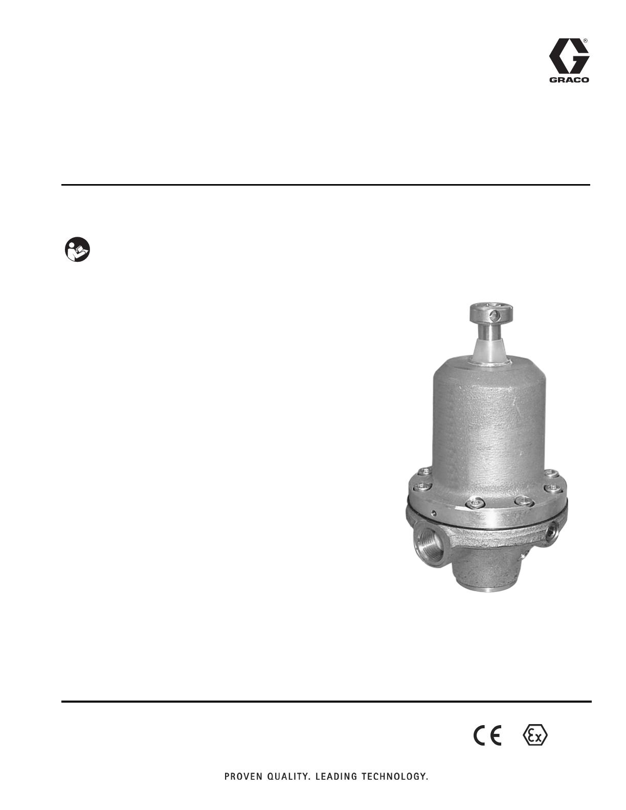
Instructions/Parts List
Low Pressure
Fluid Regulators
309474K
EN
Important Safety Instructions
Read all warnings and instructions in this manual.
Save these instructions.
Model 233757 Shown
II 2 G
2 309474K
Contents
List of Models . . . . . . . . . . . . . . . . . . . . . . . . . . . . . 3
Introduction . . . . . . . . . . . . . . . . . . . . . . . . . . . . . . . 6
Back Pressure Regulators . . . . . . . . . . . . . . . . . 6
Fluid Pressure Regulators . . . . . . . . . . . . . . . . . 6
Installation . . . . . . . . . . . . . . . . . . . . . . . . . . . . . . . . 8
Operation . . . . . . . . . . . . . . . . . . . . . . . . . . . . . . . . 11
Flush Before First Use . . . . . . . . . . . . . . . . . . . 11
Pressure Relief Procedure . . . . . . . . . . . . . . . . 11
Adjusting the Regulator . . . . . . . . . . . . . . . . . . . 11
Troubleshooting . . . . . . . . . . . . . . . . . . . . . . . . . . 12
Maintenance . . . . . . . . . . . . . . . . . . . . . . . . . . . . . . 13
Flushing . . . . . . . . . . . . . . . . . . . . . . . . . . . . . . 13
Cleaning and Repair . . . . . . . . . . . . . . . . . . . . . 13
Parts . . . . . . . . . . . . . . . . . . . . . . . . . . . . . . . . . . . . 14
Mechanical Fluid Pressure Regulators
Part Nos. 233759 and 234267 . . . . . . . . . . 14
Mechanical Back Pressure Regulators
Part Nos. 233812 and 234258 . . . . . . . . . . 15
Mechanical Fluid Pressure Regulators
Part Nos. 233757, 233774, 234263, and
234273 . . . . . . . . . . . . . . . . . . . . . . . . . . . . 16
Mechanical Back Pressure Regulators
Part Nos. 233758, 233811, 233950, 234255,
234261, and 234262 . . . . . . . . . . . . . . . . . . 17
Pneumatic Fluid Pressure Regulators
Part Nos. 233773, 233809, 234272, and
234256 . . . . . . . . . . . . . . . . . . . . . . . . . . . . 18
Pneumatic Back Pressure Regulators
Part Nos. 233810 and 234257 . . . . . . . . . . 19
Technical Data . . . . . . . . . . . . . . . . . . . . . . . . . . . . 20
Accessory Gauges . . . . . . . . . . . . . . . . . . . . . . . . . 21
Flow Rate Data . . . . . . . . . . . . . . . . . . . . . . . . . . . . 21
Mounting Dimensions . . . . . . . . . . . . . . . . . . . . . . 22
Graco Warranty . . . . . . . . . . . . . . . . . . . . . . . . . . . 24
Manual Conventions
Warning
Caution
WARNING
A warning alerts you to the possibility of serious injury
or death if you do not follow the instructions.
Symbols, such as fire and explosion (shown above),
alert you to a specific hazard and direct you to read
the indicated hazard warnings (pages 4-5) for detailed
information.
CAUTION
A caution alerts you to the possibility of damage to or
destruction of equipment if you do not follow the
instructions.
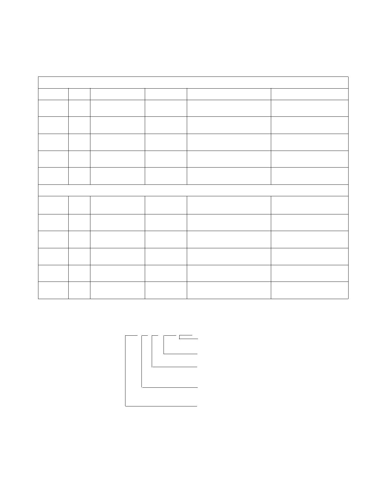
List of Models
309474K 3
List of Models
Key to Model Designation
Fluid Pressure Regulators
Part No. Series Model Type Maximum Fluid Inlet Pressure Regulated Pressure Range
233757
234263
B
B
P20-VM
P20-VM npt
Mechanical,
fluid pressure
580 psi (4000 kPa, 40 bar) 15-290 psi
(100-2000 kPa, 1-20 bar)
233759
234267
B
B
P50-VM
P50-VM npt
Mechanical,
fluid pressure
1015 psi (7000 kPa, 70 bar) 145-725 psi
(1000-5000 kPa, 10-50 bar)
233773
234272
B
B
P10-VP
P10-VP npt
Pneumatic,
fluid pressure
580 psi (4000 kPa, 40 bar) 6-145 psi
(40-1000 kPa, 0.4-10 bar)
233774
234273
B
B
P10-VM
P10-VM npt
Mechanical,
fluid pressure
580 psi (4000 kPa, 40 bar) 15-145 psi
(100-1000 kPa, 1-10 bar)
233809
234256
B
B
P10-VP, OEM
P10-VP, OEM npt
Pneumatic,
fluid pressure
580 psi (4000 kPa, 40 bar) 6-145 psi
40-1000 kPa, 0.4-10 bar)
Back Pressure Regulators
Part No. Series Model Type
Maximum Permanent Supply
Pressure
Regulated Pressure Range
233758
234262
B
B
P10-RM
P10-RM npt
Mechanical,
back pressure
145 psi (1000 kPa, 10 bar) 15-145 psi
(100-1000 kPa, 1-10 bar)
233810
234257
B
B
P10-RP
P10-RP npt
Pneumatic,
back pressure
145 psi (1000 kPa, 10 bar) 15-145 psi
(100-1000 kPa, 1-10 bar)
233811
234255
B
B
P20-RM DN13
P20-RM DN13 npt
Mechanical,
back pressure
290 psi (2000 kPa, 20 bar) 29-290 psi
(200-2000 kPa, 2-20 bar)
233812
234258
B
B
P50-RM
P50-RM npt
Mechanical,
back pressure
725 psi (5000 kPa, 50 bar) 73-725 psi
(500-5000 kPa, 5-50 bar)
233950
234261
B
B
P20-RM DN1
P20-RM DN1 npt
Mechanical,
back pressure
290 psi (2000 kPa, 20 bar) 15-290 psi
(100-2000 kPa, 1-20 bar)
Pressure regulation valve e.g. P20- R M DN13 npt
npt version
Valve Seat Orifice 13mm
Operating Mode P - pneumatic
M - mechanical
Action V - pressure regulation
R - back-pressure regulation
Regulation max 20 bar

Warning
4 309474K
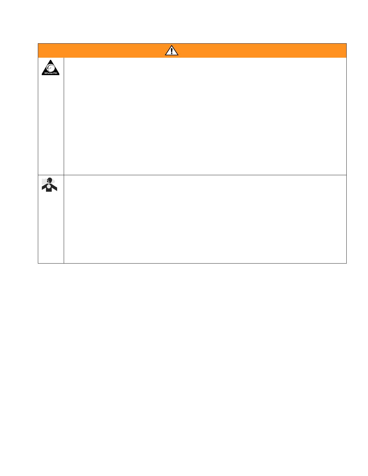
WARNING
EQUIPMENT MISUSE HAZARD
Equipment misuse can cause the equipment to rupture or malfunction and result in serious injury.
• This equipment is for professional use only.
• Read all instruction manuals, tags, and labels before operating the equipment.
• Use the equipment only for its intended purpose. If you are not sure, call your Graco distributor.
• Do not alter or modify this equipment. Use only genuine Graco parts and accessories.
• Check equipment daily. Repair or replace worn or damaged parts immediately.
• Do not exceed the maximum working pressure of the lowest rated system component. Refer to the
Technical Data on page 20 for the maximum working pressure of this equipment.
• Use fluids and solvents which are compatible with the equipment wetted parts. Refer to the Techni-
cal Data section of all equipment manuals. Read the fluid and solvent manufacturer's warnings.
• Route hoses away from traffic areas, sharp edges, moving parts, and hot surfaces. Do not expose
Graco hoses to temperatures above 180°F (82°C) or below -40°F (-40°C).
• Wear hearing protection when operating this equipment.
• Never use 1,1, 1-trichloroethane, methylene chloride, other halogenated hydrocarbon solvents or
fluids containing such solvents in pressurized aluminum equipment. Such use could result in a
chemical reaction, with the possibility of explosion.
• Comply with all applicable local, state, and national fire, electrical, and safety regulations.
Warning
309474K 5
PRESSURIZED EQUIPMENT HAZARD
Spray from the gun, hose leaks, or ruptured components can splash fluid in the eyes or on the skin and
cause serious injury.
• Do not point the gun at anyone or at any parts of the body.
• Do not stop or deflect leaks with your hand, body, glove, or rag.
•Follow the Pressure Relief Procedure on page 11 whenever you are instructed to relieve pressure;
stop spraying; clean, check, or repair the equipment; and install or clean the spray nozzle.
• Tighten all fluid connections before operating the equipment.
• Check the hoses, tubes, and couplings daily. Replace worn, damaged, or loose parts immediately.
Permanently coupled hoses cannot be repaired; replace the entire hose.
TOXIC FLUID HAZARD
Hazardous fluid or toxic fumes can cause serious injury or death if splashed in the eyes or on the skin,
inhaled, or swallowed.
• Know the specific hazards of the fluid you are using. Read the fluid manufacturer’s warnings.
• Store hazardous fluid in an approved container. Dispose of hazardous fluid according to all local,
state and national guidelines.
• Always wear protective eyewear, gloves, clothing and respirator as recommended by the fluid and
solvent manufacturer.
WARNING
Introduction
6 309474K
Introduction
A fluid pressure regulator is used in air spray systems to
ensure accurate, positive control of fluid pressure to an
air spray gun or to a low pressure dispensing valve or
atomizing head.
A regulator installed at a circulating line take-off or pump
reduces main line pressure to maintain the desired fluid
pressure to the air spray gun or to a low pressure dis-
pensing valve or atomizing head.
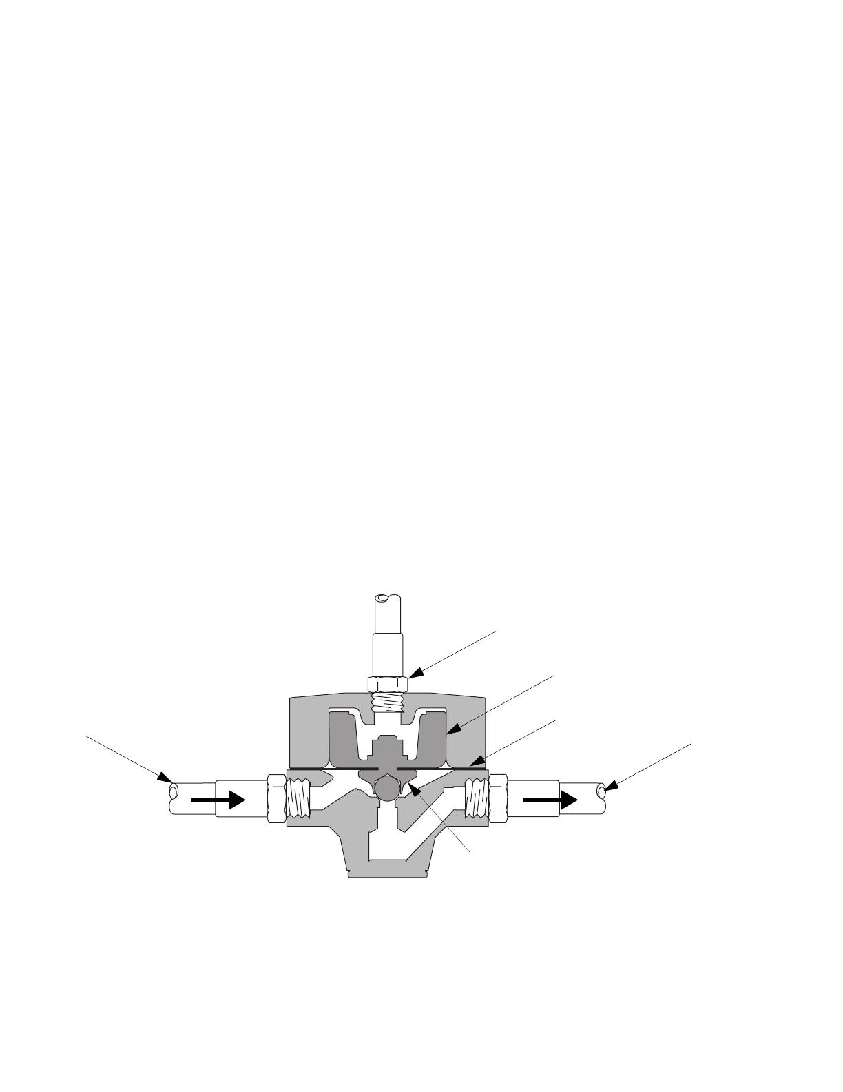
Back Pressure Regulators
Models 233810, 233811, 233812, 233950, 234255,
234257, 234258, 233758, 234261, and 234262, are
back pressure regulators that limit the supply pressure
to a set value by opening an outlet and guiding back
excess material when the predetermined pressure has
been achieved. These valves are used in circulating
systems. Model 233810 pneumatic back pressure regu-
lator is shown in F
IG
. 1.
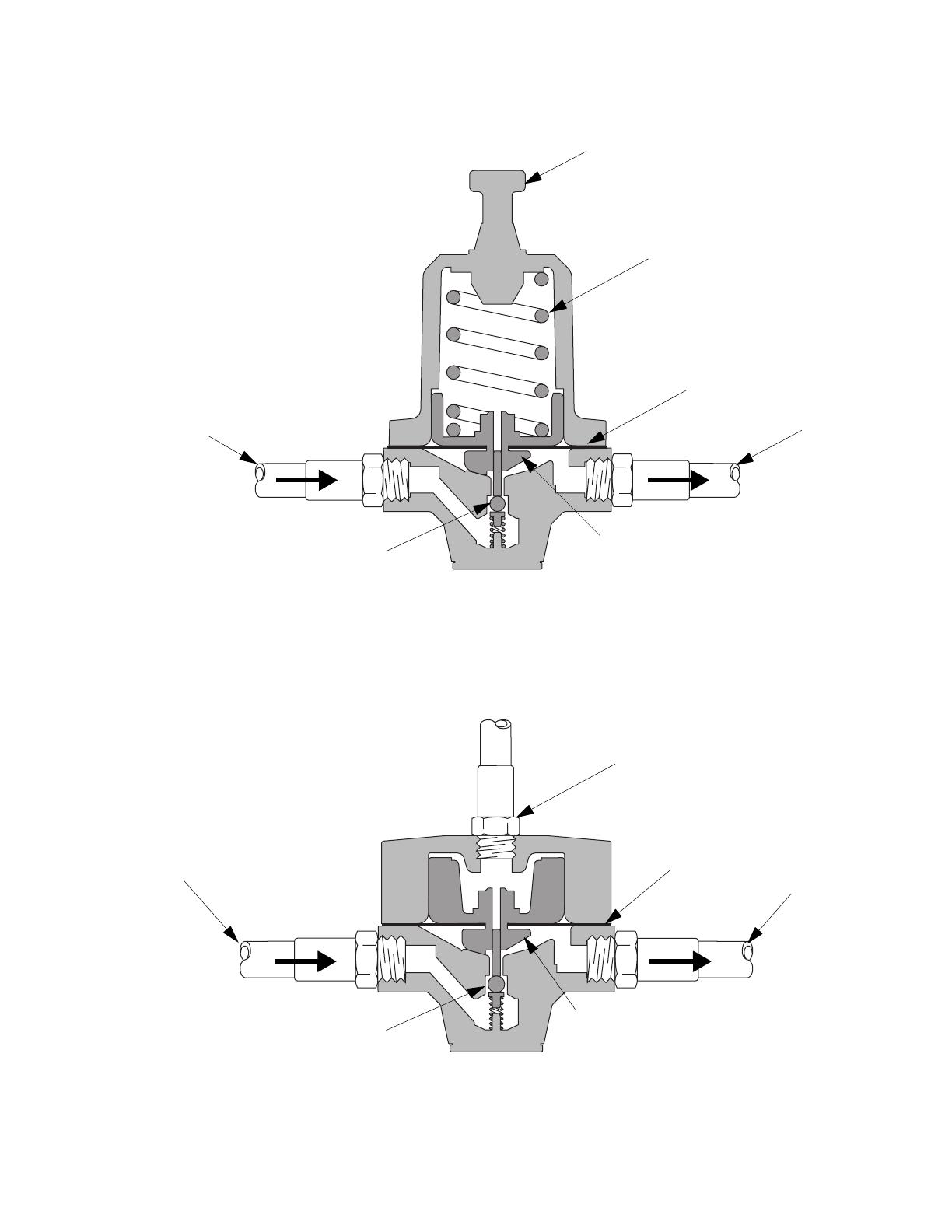
Fluid Pressure Regulators
Models 233757, 233759, 233774, 234263, 234267, and
234273 (F
IG
. 2.) are mechanically operated fluid pres-
sure regulators designed primarily for use with low to
medium viscosity fluids.
Models 233773, 233809, 234256, and 234272 (F
IG
. 3.)
are pneumatically operated fluid pressure regulators
designed primarily for use with highly viscous coatings.
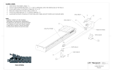
Fig. 1. Cutaway of Pneumatic Back Pressure Regulator
TI1773A
Piston
Valve plunger
Fluid Outlet
(return line)
Air inlet
Fluid Inlet
(from gun)
Diaphragm
Introduction
309474K 7
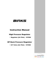
Fig. 2. Cutaway of Mechanical Fluid Pressure Regulator
Fig. 3. Cutaway of Pneumatic Fluid Pressure Regulator
TI1772A
Spring
Valve plunger
Fluid Outlet
(to gun)
Adjustment screw
Fluid Inlet
(from pump)
Diaphragm
Valve ball and seat
TI1772B
TI1771A
Valve plunger
Fluid Outlet
(to gun)
Air inlet
Fluid Inlet
(from pump)
Diaphragm
Valve ball and seat
TI1771B
Installation
8 309474K
Installation
1. Install one regulator for each spray gun.
2. Apply thread sealant to connections as necessary.
3. Make sure that the direction of fluid flow agrees with
the flow direction markings on the regulator body.
a. Install a fluid pressure regulator
upstream
of the
gun: Connect the fluid line from the pump to the
inlet of the fluid regulator. Connect the fluid line
to the gun to the regulator’s outlet.
b. Install a back pressure regulator
downstream
of
the gun. Connect the fluid return line from the
gun to the inlet of the back pressure regulator.
Connect the fluid return line to the pump to the
regulator’s outlet.
4. Flush and test the entire system.
F
IG
. 4., F
IG
. 5., and F
IG
. 6. show possible configurations
for installing a system. They do not depict actual system
designs. Consult your Graco distributor for assistance in
designing a system that meets your specific require-
ments.
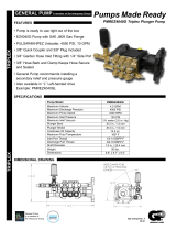
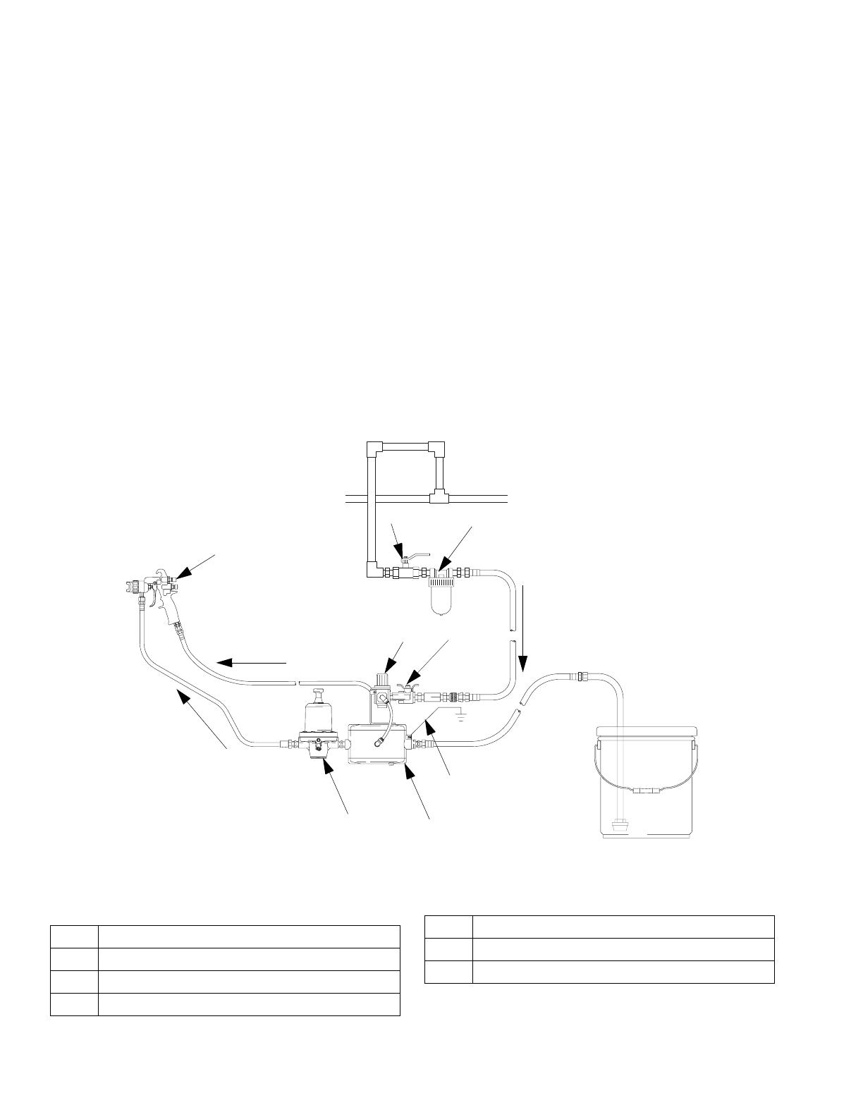
Fig. 4. Low pressure, non-circulating system, mechanical fluid regulator
Key
A
B
C
DE
F
Fluid
Air to gun
Air to pump
Y
B
TI1767A
A Air line filter
B Bleed-type air shut-off valve
C Air regulator for pump and gun
DPump
E Fluid regulator
F Air spray gun
Y Pump ground wire
Installation
309474K 9
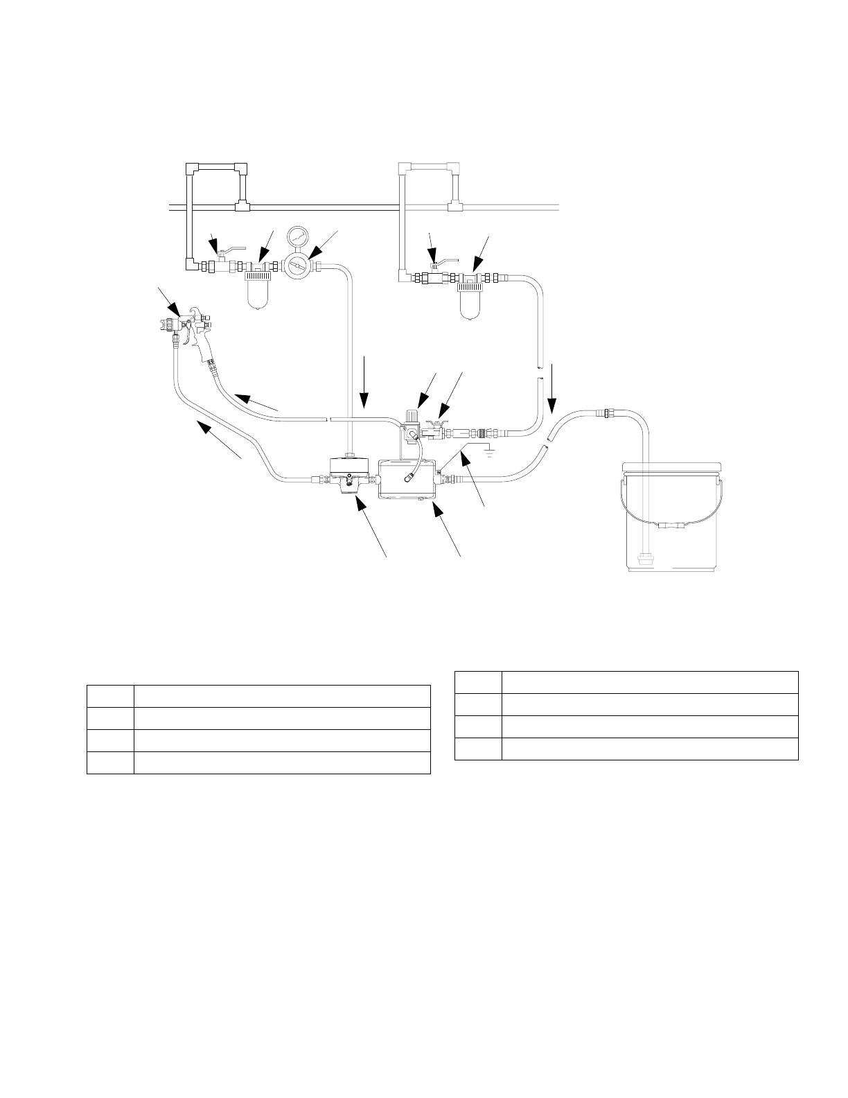
Fig. 5. Low pressure, non-circulating system, pneumatic fluid regulator
Key
A
C
D
B
F
G
Air to Fluid
Regulator
Air to
Gun
Air to
Pump
F
l
u
i
d
Y
E
B
AB
TI1766A
A Air line filter
B Bleed-type air shut-off valve
C Air regulator for pump and gun
DPump
E Fluid regulator
F Air spray gun
G Air regulator for fluid regulator
Y Pump ground wire
Installation
10 309474K
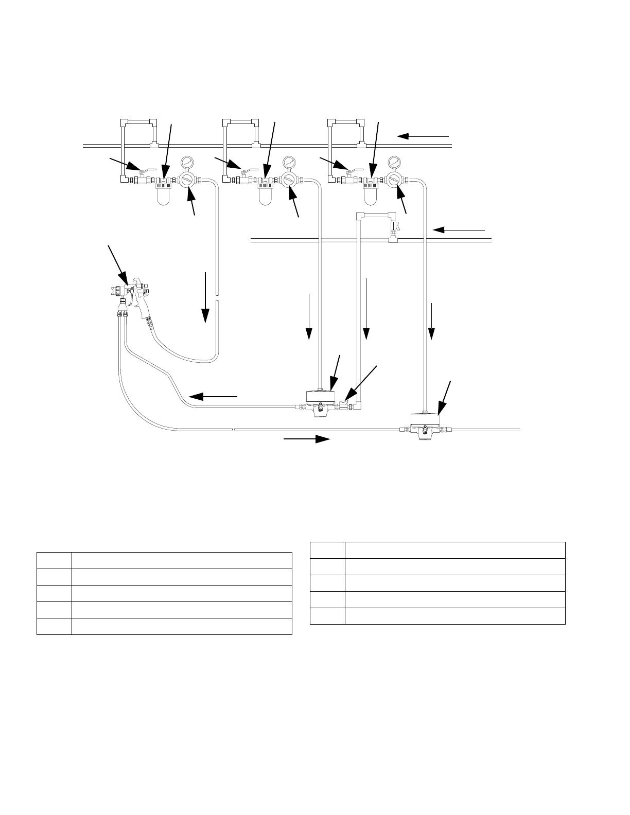
Fig. 6. Low Pressure circulating system, pneumatic fluid regulator and back pressure regulator
Key
A
B
J
Air to
gun
Fluid
to gun
H
C
A
B
A
B
KG
Air to Fluid
Regulator
Air to Back
Pressure
Regulator
E
Fluid return from gun
Fluid
Fluid
F
Air
TI1768A
A Air line filter
B Bleed-type air shut-off valve
C Air regulator for pump and gun
E Fluid regulator
F Air spray gun
G Air regulator for fluid regulator
H Fluid shutoff valve
J Back pressure regulator
K Air regulator for back pressure regulator
Y Pump ground wire
Operation
309474K 11
Operation
Flush Before First Use
Your pressure regulator has been tested in the factory
with an anti-corrosion liquid. Before using the regulator,
thoroughly flush the system with a solvent to remove
residue of this liquid as well as any contaminants that
have been introduced during assembly of the system.
Pressure Relief Procedure
1. Shut off the air to the pump.
2. Trigger the air spray gun to relieve the fluid pres-
sure.
3. Open the fluid drain valve to relieve all fluid pres-
sure, having a container ready to catch the drain-
age.
Adjusting the Regulator
The fluid pressure regulator controls pressure down-
stream from its outlet. The inlet fluid pressure should
always be higher than the outlet fluid pressure.
If you are using an accessory fluid pressure gauge, trig-
ger the air spray gun to relieve pressure in the line when
reducing the pressure, to ensure a correct gauge read-
ing.
Adjust the pump air pressure and the fluid pressure reg-
ulator for the best spraying combination.
In a circulating system, the back pressure valve controls
the fluid pressure upstream of its inlet in the same way.
Mechanical Regulator
1. Back out the adjustment screw until there is no
spring pressure.
2. Turn on the fluid supply, to admit fluid to the regula-
tor.
3. Turn the screw clockwise to adjust fluid pressure to
the desired level.
Pneumatic Regulator
1. With the fluid supply shut off, turn on the air pres-
sure to the regulator.
2. Turn on the fluid supply, to admit fluid to the regula-
tor.
3. Increase the fluid inlet pressure. When the fluid out-
let pressure is at the desired level, shut off the air to
the fluid regulator.
WARNING
Read the warnings on page 5, and follow the Pressure
Relief Procedure below whenever you:
• are instructed to relieve pressure
• stop spraying
• check or service any of the equipment
• install or clean the fluid nozzle.
Troubleshooting
12 309474K
Troubleshooting
Relieve the pressure (page 11) before checking or repairing the equipment.
To repair the regulator, refer to page 13.
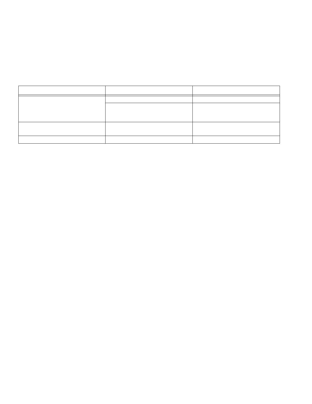
Problem Cause Solution
Drop in fluid outlet pressure. Ruptured diaphragm (15). Replace diaphragm.
Air escaping (pneumatic regulators
only).
Check air hose and connections.
Replace piston seal (21).
Fluid outlet pressure increases to
level of fluid inlet pressure.
Valve ball (5) and seat (2) are worn
or stuck open.
Clean ball and seat. Replace worn or
damaged parts.
Fluid leaking from upper housing. Ruptured diaphragm (15). Replace diaphragm.

Maintenance
309474K 13
Maintenance
Flushing
Flush before changing colors, at the end of the day,
before storing, and before repairing the equipment.
Flush with a fluid that is compatible with the fluid you are
pumping and with the wetted parts of your system.
Check with your fluid manufacturer or supplier for rec-
ommended flushing fluids and flushing frequency.
Relieve the pressure after flushing.
Do not allow paint or solvent to sit in the system for
extended periods. Fluid could dry in the regulator and
cause leakage. If leakage occurs, relieve pressure, then
disassemble and clean the regulator.
Cleaning and Repair
When changing fluids or colors, the regulator should be
disassembled and cleaned. Regular cleaning and
inspection of the internal parts is necessary to keep the
fluid regulator working properly.
1. Relieve all air and fluid pressure in the system.
2. Remove the regulator from the system.
3. Disassemble the regulator (see the parts drawings
on pages 14 through 19).
4. Clean and inspect all parts.
5. Inspect the diaphragm, packings, o-rings, and seals
for wear. Check the ball and seat for nicks, wear, or
other damage.
6. Lubricate packings, o-rings and seals when reas-
sembling the regulator.
CAUTION
Be very careful when handling the carbide balls and
seats. Damage will cause poor operation and leak-
age.

Parts
14 309474K
Parts
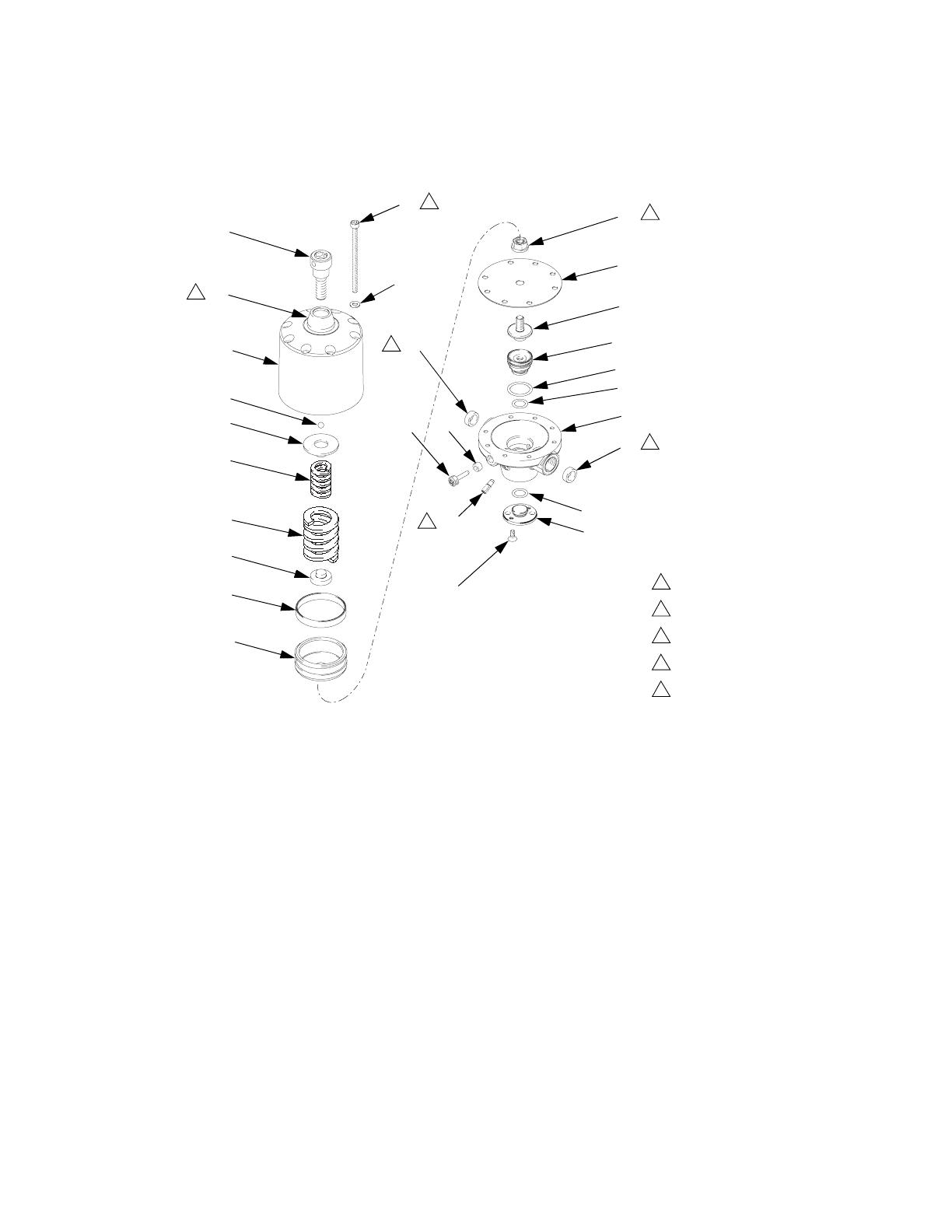
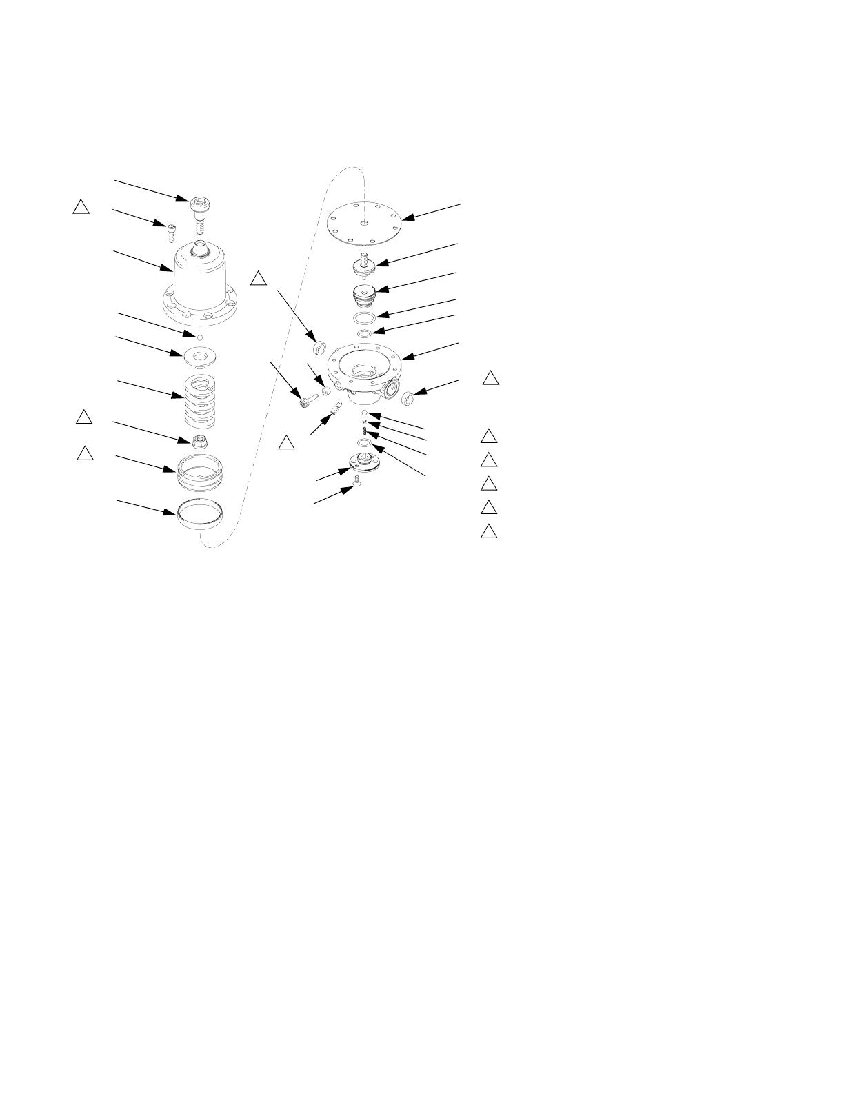
Mechanical Fluid Pressure Regulators
Part Nos. 233759 and 234267
TI1753A
28
25
26
24
22
21
20
19
18
10
12
13
11
17
15
14
2
3
4
1
10
5
6
7
4
8
9
23
16
27
Torque to 6 N•m (53 in-lb).
Torque to 2 N•m (18 in-lb).
Fill internal cavity with grease.
Used only on non-npt model 233759.
Torque to 5 N•m (44in-lb).
1
2
3
5
6
2
1
3
5
5
6
Ref.
No. Part No. Description
Qty
1 HOUSING, lower, for 233759 1
HOUSING, lower, for 234267 1
2 245368 SEAT, valve 1
3 15Y036 O-RING 1
4 15Y035 O-RING 2
5 117106 BALL, 6 mm, carbide 1
6 15A205 SUPPORT, ball 1
7 117090 SPRING, compression 1
8 15A144 COVER 1
9 117123 SCREW, fhms, M4x10 2
10 15A219 RING, for non-npt model 233759
only
2
11 117101 PLUG, threaded 2
12 117085 SEAL, ring 1
13 117099 PLUG, threaded 1
14 245372 PLUNGER, valve 1
15 15A179 DIAPHRAGM 1
16 15A173 CAP, spring 1
17 117122 NUT, seal-lock 1
18 15A175 PLATE, spring, bottom 1
19 117096 SPRING, compression 1
20 117092 SPRING, compression 1
21 15A176 PLATE, spring, top 1
22 117105 BALL, 6 mm 1
23 15A186 PACKING, PTFE with carbon 1
24 245366 HOUSING, upper 1
25 117129 SCREW, shcs, M5x80 8
26 117017 WASHER 8
27 15A141 BONNET, cover 1
28 15A242 SCREW, custom 1
Ref.
No. Part No. Description
Qty
Parts
309474K 15
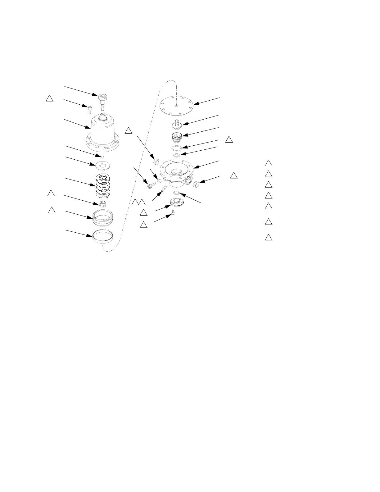
Mechanical Back Pressure Regulators
Part Nos. 233812 and 234258
Torque to 6 N•m (53 in-lb).
Torque to 2 N•m (18 in-lb).
Fill internal cavity with grease.
Used only on non-npt model 233812.
Torque to 5 N•m (44in-lb).
1
2
3
5
6
28
25
26
24
22
21
20
19
18
10
12
13
11
17
15
14
2
3
4
1
10
4
8
9
23
16
27
2
1
3
5
5
TI11248a
6
Ref.
No. Part No. Description
Qty
1 HOUSING, lower, for 233812 1
HOUSING, lower, for 234258 1
2 245369 SEAT, valve 1
315Y036O-RING 1
415Y035O-RING 2
8 15A143 COVER 1
9 117123 SCREW, fhms, M4x10 2
10 15A219 RING, for non-npt model 233812
only
2
11 117101 PLUG, threaded 2
12 117085 SEAL, ring 1
13 117099 PLUG, threaded 1
14 245373 PLUNGER, valve 1
15 15A179 DIAPHRAGM 1
16 15A173 CAP, spring 1
17 117122 NUT, seal-lock 1
18 15A175 PLATE, spring, bottom 1
19 117096 SPRING, compression 1
20 117092 SPRING, compression 1
21 15A176 PLATE, spring, top 1
22 117108 BALL, 8 mm 1
23 15A186 PACKING, PTFE with carbon 1
24 245366 HOUSING, upper 1
25 117129 SCREW, shcs, M5x80 8
26 117017 WASHER 8
27 15A141 BONNET, cover 1
28 15A242 SCREW, custom 1
Ref.
No. Part No. Description
Qty
Parts
16 309474K
Mechanical Fluid Pressure Regulators
Part Nos. 233757, 233774, 234263, and 234273
TI1751A
3
4
28
25
24
22
21
19
10
1213
11
17
15
14
2
3
4
1
10
5
6
7
4
8
9
23
16
2
1
5
5
Torque to 4-5 N•m (35-44 in-lb).
Torque to 2 N•m (18 in-lb).
Torque to 5 N•m (44 in-lb).
Grease OD.
Used only on non-npt models 233757 and 233774.
1
2
3
4
5
Ref.
No. Part No. Description
Qty
1 HOUSING, lower, for 233757 and
233774
1
HOUSING, lower, for 234263 and
234273
1
2 245368 SEAT, valve 1
3 15Y036 O-RING 1
4 15Y035 O-RING 2
5 117106 BALL, 6 mm, carbide 1
6 15A205 SUPPORT, ball 1
7 117090 SPRING, compression 1
8 15A144 COVER 1
9 117123 SCREW, fhms, M4x10 2
10 15A219 RING, for non-npt models 233757
and 233774 only
2
11 117101 PLUG, threaded 2
12 117085 SEAL, ring 1
13 117099 PLUG, threaded 1
14 245372 PLUNGER, valve 1
15 15A179 DIAPHRAGM 1
16 15A172 CAP, spring 1
17 117122 NUT, seal-lock 1
19 117087 SPRING, compression, for 233774
and 234273
1
117095 SPRING, compression, for 233757
and 234263
1
21 15A177 PLATE, spring, top 1
22 117105 BALL, 6 mm 1
23 15A185 PACKING, PTFE with carbon 1
24 245365 HOUSING, upper 1
25 117126 SCREW, shcs, M5x16 8
28 15A241 SCREW, custom 1
Ref.
No. Part No. Description
Qty
Parts
309474K 17
Mechanical Back Pressure Regulators
Part Nos. 233758, 233811, 233950, 234255, 234261, and 234262
3
4
28
25
24
22
21
19
10
12
13
11
17
15
14
2
3
4
1
10
4
8
9
23
16
2
1
5
5
Torque to 4-5 N•m (35-44 in-lb).
Torque to 2 N•m (18 in-lb).
Torque to 5 N•m (44 in-lb).
Grease OD.
Used only on non-npt models
233758, 233950, and 233811.
Not used on models 233811 and
234255.
Models 233811 and 234255 use a
plug and retaining ring (not shown).
1
2
3
4
5
6
7
6
7
6
6
TI11249a
Ref.
No. Part No. Description
Qty
1 HOUSING, lower, for 233758 and
233950
1
HOUSING, lower for 234262 and
234261
1
15A198 HOUSING, lower, for 233811 1
15C303 HOUSING, lower, for 234255 1
2 245369 SEAT, valve, for 233758, 233950,
234261, and 234262
1
15A228 SEAT, valve, for 233811 and
234255
1
3 15Y036 O-RING, not used on models
233811 and 234255
1
4 15Y035 O-RING, for 233758, 233950,
234261, and 234262
2
15Y031 O-RING, for 233811 and 234255 2
8 15A143 COVER, for 233758, 233950,
234261, and 234262
1
15A222 PLUG, for 233811 and 234255 1
9 117123 SCREW, fhms, M4x10, not used on
models 233811 and 234255
2
10 15A219 RING, for non-npt models 233758,
and 233950
2
15A221 RING, for non-npt model 233811 2
11 117101 PLUG, threaded, not used on mod-
els 233811 and 234255
2
12 117085 SEAL, ring 1
13 117099 PLUG, threaded 1
14 245373 PLUNGER, valve, for 233758,
233950, 234261, and 234262
1
245378 PLUNGER, valve, for 233811 and
234255
1
15 15A179 DIAPHRAGM 1
16 15A172 CAP, spring 1
17 117122 NUT, seal-lock 1
19 117087 SPRING, compression, for 233758
and 234262
1
117095 SPRING, compression, for 233811,
233950, 234261, and 234255
1
21 15A177 PLATE, spring, top 1
22 117105 BALL, 6 mm 1
23 15A185 PACKING, PTFE with carbon 1
24 245365 HOUSING, upper 1
25 117126 SCREW, shcs, M5x16 8
28 15A241 SCREW, custom 1
29 117124 RING, retaining, 233811 and
234255 only
1
Ref.
No. Part No. Description
Qty

Parts
18 309474K
Pneumatic Fluid Pressure Regulators
Part Nos. 233773, 233809, 234272, and 234256
TI1755A
25
24
21
17
10
12
13
11
15
14
2
3
4
1
10
5
6
7
4
8
9
23
16
2
1
3
4
26
27
Torque to 4-5 N•m (35-44 in-lb).
Torque to 2 N•m (18 in-lb).
Torque to 5 N•m (44 in-lb).
Grease OD.
Used only on non-npt models
233773 and 233809.
Used only on npt models
234272 and 234256.
1
2
3
4
5
6
5
5
6
6
Ref.
No. Part No. Description Qty.
1 HOUSING, lower, for 233773 and
233809
1
HOUSING, lower, for 234272 and
234256
1
2 245368 SEAT, valve, for 233773 and
234272
1
245371 SEAT, valve, for 233809 and
234256
1
3 15Y036 O-RING 1
4 15Y035 O-RING 1
5 117106 BALL, 6 mm, carbide, for 233773
and 234272
1
117110 BALL, 6 mm, for 233809 and
234256
1
6 15A205 SUPPORT, ball 1
7 117090 SPRING, compression 1
8 15A144 COVER 1
9 117123 SCREW, fhms, M4x10 2
10 15A219 RING, for non-npt models 233773
and 233809
2
11 117101 PLUG, threaded 2
12 117085 SEAL, ring 1
13 117099 PLUG, threaded 1
14 245372 PLUNGER, valve 1
15 15A179 DIAPHRAGM 1
16 15A204 PISTON 1
17 117122 NUT, seal-lock 1
21 117102 SEAL, flat 1
23 15A185 PACKING, PTFE with carbon 1
24 15A191 HOUSING, upper 1
25 117127 SCREW, shcs, M5x35 8
26 15C332 FITTING, for npt models 234272
and 234256 only
1
27 15C333 WASHER, for npt models 234272
and 234256 only
1
Ref.
No. Part No. Description Qty.

Parts
309474K 19
Pneumatic Back Pressure Regulators
Part Nos. 233810 and 234257
25
24
21
17
10
12
13
11
15
14
2
3
4
1
10
4
8
9
23
16
2
1
3
4
26
27
Torque to 4-5 N•m (35-44 in-lb).
Torque to 2 N•m (18 in-lb).
Torque to 5 N•m (44 in-lb).
Grease OD.
Used only on non-npt model 233810.
Used only on npt model 234257.
1
2
3
4
5
6
5
5
TI11250a
6
6
Ref.
No. Part No. Description Qty.
1 HOUSING, lower, for 233810 1
HOUSING, lower, for 234257 1
2 245369 SEAT, valve 1
3 15Y036 O-RING 1
4 15Y035 O-RING 1
8 15A143 COVER 1
9 117123 SCREW, fhms, M4x10 2
10 15A219 RING, for non-npt model 233810 2
11 117101 PLUG, threaded 2
12 117085 SEAL, ring 1
13 117099 PLUG, threaded 1
14 245373 PLUNGER, valve 1
15 15A179 DIAPHRAGM 1
16 15A204 PISTON 1
17 117122 NUT, seal-lock 1
21 117102 SEAL, flat 1
23 15A185 PACKING, PTFE with carbon 1
24 15A191 HOUSING, upper 1
25 117127 SCREW, shcs, M5x35 8
26 15C332 FITTING, for npt model 234257
only
1
27 15C333 WASHER, for npt model 234257
only
1
Ref.
No. Part No. Description Qty.

Technical Data
20 309474K
Technical Data
* Accessory gauges available.
Category Data
Maximum Fluid Inlet Pressure
(Fluid Pressure Regulators)
233757, 233773, 233774, 233809,
234256, 234263, 234272, 234273 :
580 psi (4000 kPa, 40 bar)
233759, 234267:
1015 psi (7000 kPa, 70 bar)
Maximum Permanent Supply Pres-
sure (Back Pressure Regulators)
233758, 233810, 234257, 234262:
145 psi (1000 kPa, 10 bar)
233811, 233950, 234255, 234261:
290 psi (2000 kPa, 20 bar)
233812
, 234258: 725 psi (5000 kPa, 50 bar)
Pressure Range
233773, 233809, 234272, 234256:
6-145 psi (40-1000 kPa, 0.4-10 bar)
233758, 233774, 233810,
234257,234262, 234273 :
15-145 psi (100-1000 kPa, 1-10 bar)
233757, 234263:
15-290 psi (100-2000 kPa, 1-20 bar)
233811, 233950, 234255, 234261:
29-290 psi (200-2000 kPa, 2-20 bar)
233812, 234258:
73-725 psi (500-5000 kPa, 5-50 bar)
233759, 234267:
145-725 psi (1000-5000 kPa, 10-50 bar)
Maximum Operating Air Pressure
(Pneumatic Regulators Only)
145 psi (1 MPa, 10 bar)
Maximum Flow Rate See chart on page 21.
Temperature Range
233757, 233758, 233759, 233773, 233774, 233809, 233810, 233811, 233950,
234255, 234256, 234261, 234262, 234263, 234273:
32-194°F (0-90°C)
233812, 234258:
50-176°F (10-80°C)
Fluid inlet and outlet
233757, 233758, 233759, 233773, 233774,
233809, 233810, 233812, 233950:
3/8 in. BSPP(F)
234256, 234257, 234258, 234261,
234262, 234263, 234267, 234272, 234273: 3/8 in. npt(f)
233811:
1 in. BSPP(F)
234255: 1 in. npt(f)
Air inlet
233773, 233809, 233810:
1/4 in. BSPP(F)
234256, 234257, 234272: 1/4 in. npt(m)
*Gauge port 1/8 in. BSPP(F)
Wetted Parts Stainless steel, tungsten carbide, PTFE, chemically resistant fluoroelastomer,
PEEK
(233809 and 234256 only)
/