Graco 243775 User manual

Category
Power fine-spray systems
Type
User manual
Instructions – Parts List
WATERBASE COMPATIBLE
Ultra–litet Pistol Grip
Flo–Gun
Model 235627, Series B
4000 psi (280 bar) Maximum Working Pressure
Tapered Valve Needle
Model 235628, Series D
6000 psi (415 bar) Maximum Working Pressure
Ball End Valve Needle, Abrasive Material Compatible
Model 243775, Series B
6000 psi (415 bar) Maximum Working Pressure
Tapered Valve Needle
Model 237607, Series A
4000 psi (280 bar) Maximum Working Pressure
Tapered Valve Needle, Abrasive Material Compatible
Model 237649, Series A
4000 psi (280 bar) Maximum Working Pressure
Tapered Valve Needle, Abrasive Material Compatible,
Swivel Fitting Fluid Inlet
U.S. Patent No. Des. 342,654
Symbols 2. . . . . . . . . . . . . . . . . . . . . . . . . . . . . . . . . . . . . .
Warning 2. . . . . . . . . . . . . . . . . . . . . . . . . . . . . . . . . . . . . . .
Technical Data 4. . . . . . . . . . . . . . . . . . . . . . . . . . . . . . . . .
Installation 5. . . . . . . . . . . . . . . . . . . . . . . . . . . . . . . . . . . . .
Operation 6. . . . . . . . . . . . . . . . . . . . . . . . . . . . . . . . . . . . .
Service 8. . . . . . . . . . . . . . . . . . . . . . . . . . . . . . . . . . . . . . .
Parts 14. . . . . . . . . . . . . . . . . . . . . . . . . . . . . . . . . . . . . . . .
Graco Warranty and Limitation of Liability 22. . . . . . . . .
Graco Phone Number 22. . . . . . . . . . . . . . . . . . . . . . . . . .
308253N
EN
Important Safety Instructions
Read all warnings and instructions in this manual.
Save these instructions.
01609A
2 308253
Symbols
Warning Symbol
WARNING
This symbol alerts you to the possibility of serious
injury or death if you do not follow the instructions.
Caution Symbol
CAUTION
This symbol alerts you to the possibility of damage to
or destruction of equipment if you do not follow the
instructions.
WARNING
SKIN INJECTION HAZARD
Spray from the gun, hose leaks, or ruptured components can inject fluid into your body and cause
extremely serious injury, including the need for amputation. Splashing fluid in the eyes or on the skin
can also cause serious injury.
Fluid injected into the skin might look like just a cut, but it is a serious injury. Get immediate surgi-
cal treatment.
Do not point the gun at anyone or at any part of the body.
Do not put hand or fingers over the gun nozzle.
Do not stop or deflect fluid leaks with your hand, body, glove, or rag.
Be sure the gun trigger safety operates before dispensing.
Lock the gun trigger safety when you stop dispensing.
If the nozzle clogs while dispensing, fully release the trigger immediately
Follow the Pressure Relief Procedure on page 6 whenever you: are instructed to relieve pres-
sure; stop spraying; clean, check, or service the equipment; and install or clean the nozzle.
Tighten all the fluid connections before operating the equipment.
Check the hoses, tubes, and couplings daily. Replace worn, damaged, or loose parts immediately.
Permanently coupled hoses cannot be repaired; replace the entire hose.
TOXIC FLUID HAZARD
Hazardous fluids or toxic fumes can cause a serious injury or death if splashed in the eyes or on the
skin, swallowed, or inhaled.
Know the specific hazards of the fluid you are using. Read the fluid manufacturer’s warnings.
Store hazardous fluid in an approved container. Dispose of the hazardous fluid according to all
local, state, and national guidelines.
Wear appropriate protective clothing, gloves, eyewear, and respirator.
308253 3
WARNING
FIRE AND EXPLOSION HAZARD
Improper grounding, poor air ventilation, open flames, or sparks can cause a hazardous condition and
result in a fire or explosion and serious injury.
Ground the equipment and the object being sprayed. See Ground the System on page 5.
Provide fresh air ventilation to avoid the buildup of flammable fumes from solvent or the fluid being
sprayed.
Extinguish all the open flames or pilot lights in the spray area.
Electrically disconnect all the equipment in the spray area.
Keep the spray area free of debris, including solvent, rags, and gasoline.
Do not turn on or off any light switch in the spray area while operating or if fumes are present.
Do not smoke in the spray area.
Do not operate a gasoline engine in the spray area.
If there is any static sparking while using the equipment, stop spraying immediately. Identify and
correct the problem.
INSTRUCTIONS
EQUIPMENT MISUSE HAZARD
Equipment misuse can cause the equipment to rupture, malfunction, or start unexpectedly and result
in a serious injury.
This equipment is for professional use only.
Read all the instruction manuals, tags, and labels before operating the equipment.
Use the equipment only for its intended purpose. If you are uncertain about usage, call your Graco
distributor.
Do not alter or modify this equipment. Use only genuine Graco parts and accessories.
Check the equipment daily. Repair or replace worn or damaged parts immediately.
Do not exceed the maximum working pressure of the lowest rated system component. See the
front cover or the Technical Data for the maximum working pressure of your gun model.
Route the hoses away from the traffic areas, sharp edges, moving parts, and hot surfaces. Do not
expose Graco hoses to temperatures above 180F (82C) or below –40F (–40C).
Do not use the hoses to pull the equipment.
Use only Graco approved hoses. Do not remove hose spring guards, which help protect the hose
from rupture caused by kinks or bends near the couplings.
Use fluids or solvents that are compatible with the equipment wetted parts. See the Technical
Data section of all the equipment manuals. Read the fluid and solvent manufacturers warnings.
Do not use 1,1, 1-trichloroethane, methylene chloride, other halogenated hydrocarbon solvents or
fluids containing such solvents with gun Models 235627, 237607, and 237649. Such use could
result in a serious chemical reaction with the gun’s aluminum parts, with the possibility of an explo-
sion.
Comply with all applicable local, state and national fire, electrical and other safety regulations.
4 308253
Technical Data
Maximum Working Pressure
Models 235627, 237607,
and 237649 4000 psi (280 bar). . . . . . . . . . . . .
Models 235628 and 243775 6000 psi (415 bar). . .
Outlet Port Size
All Models 1/4 npt(f) with nut for metal. . . . . . . . . .
flanged nozzle
Inlet Port Size
Models 235627 and 237607 1/4 npt(f). . . . . . . . . . .
Models 235628 and 243775 1/2 npt(f). . . . . . . . . . .
Model 237649 37 SAE, 1/2-20 UNF(m). . . . . . . . .
Valve Orifice
Models 235627, 237607, 243775,
and 237649 0.20 in. (5.08 mm) dia.. . . . . . . . .
with tapered needle
Model 235628 0.19 in. (4.83 mm) dia. with. . . . . . .
0.25 in. (6.35 mm) carbide ball
Height
All Models 5.90 in. (149.86 mm). . . . . . . . . . . . . . . .
Width
All Models 1.20 in. (30.48 mm). . . . . . . . . . . . . . . . .
Length
Models 235627, 235628, 243775
and 237607 8.05 in. (204.47 mm). . . . . . . . . . .
Model 237649 8.90 in. (226.06 mm). . . . . . . . . . . . .
Weight
Model 235627 15.45 oz. (439 g). . . . . . . . . . . . . . . .
Model 235628 and 243775 22.70 oz. (636 g). . . . .
Model 237607 15.45 oz. (439 g). . . . . . . . . . . . . . . .
Model 237649 17.00 oz. (483 g). . . . . . . . . . . . . . . .
Wetted Parts
Model 235627
Fluid Section Aluminum. . . . . . . . . . . . . . . . . . .
Fluid Tube 300 Series Stainless Steel. . . . . . . .
Valve Needle 17-4 PH Stainless Steel. . . . . . .
Valve Seat 17-4 PH Stainless Steel. . . . . . . . .
Other 316 Stainless Steel, fluoroelastomer,. . .
and Polyurethane
Model 235628
Fluid Section 17–4 PH Stainless Steel. . . . . . .
Fluid Tube 300 Series Stainless Steel. . . . . . . .
Valve Needle Carbide and 17–4 PH. . . . . . . . .
Stainless Steel
Valve Seat Carbide and 17–4 PH. . . . . . . . . . .
Stainless Steel
Other Stainless Steel, fluoroelastomer, PTFE.
;CV75,
and Polyurethane
Model 243775
Fluid Section 17–4 PH Stainless Steel. . . . . . .
Fluid Tube 300 Series Stainless Steel. . . . . . . .
Valve Needle Carbide and 17–4 PH. . . . . . . . .
Stainless Steel
Valve Seat Carbide and 17–4 PH
. . . . . . . . . . .
Stainless Steel
Other Stainless Steel, fluoroelastomer, PTFE,
and Polyurethane
Model 237607
Fluid Section Aluminum. . . . . . . . . . . . . . . . . . .
Fluid Tube 300 Series Stainless Steel. . . . . . . .
Valve Needle Carbide and 17-4 PH . . . . . . . . .
Stainless Steel
Valve Seat Carbide and 17-4 PH . . . . . . . . . . .
Stainless Steel
Other 316 Stainless Steel, fluoroelastomer,. . .
and Polyurethane
Model 237649
Fluid Section Aluminum. . . . . . . . . . . . . . . . . . .
Fluid Tube 300 Series Stainless Steel. . . . . . . .
Valve Needle Carbide and 17-4 PH . . . . . . . . .
Stainless Steel
Valve Seat Carbide and 17-4 PH . . . . . . . . . . .
300 Series Stainless Steel
Swivel Inlet Fitting 303 Stainless Steel, and. . .
Ultra High Molecular Weight Polyethylene
Other 316 Stainless Steel, fluoroelastomer,. . .
and Polyurethane
308253 5
Installation
Ground the System
WARNING
FIRE AND EXPLOSION HAZARD
To reduce the risk of a fire, explosion,
and serious injury, proper electrical
grounding of every part of your system is
essential. Read the warning section,
FIRE AND EXPLOSION HAZARD, on
page 3 and follow the grounding
instructions below.
The following grounding instructions are minimum
requirements for a basic dispensing system. Your
system may include other equipment or objects which
must be grounded. Check your local electrical code for
detailed grounding instructions for your area and type
of equipment. Your system must be connected to a
true earth ground.
1. Pump: ground the pump by connecting a ground
wire and clamp as described in your separate
pump instruction manual.
2. Air compressors and hydraulic power
supplies: ground the equipment according to the
manufacturer’s recommendations.
3. Fluid hoses: use only grounded fluid hoses with a
maximum of 500 feet (150 m) combined hose
length to ensure grounding continuity. Check the
electrical resistance of your fluid hoses at least
once a week. If your hose does not have a tag on
it which specifies the maximum electrical resis-
tance, contact the hose supplier or manufacturer
for the maximum resistance limits. If the hose
resistance exceeds the recommended limits,
replace it immediately.
4. Flo-gun: ground the gun by connecting it to a
properly grounded fluid hose and pump.
5. Fluid supply container: ground according to the
local code.
6. Flammable liquids in the spray area: must be
kept in approved, grounded containers. Do not
store more than the quantity needed for one shift.
7. All solvent pails used when flushing: ground
according to local code. Use only metal pails,
which are conductive. Do not place the pail on a
non-conductive surface, such as paper or card-
board, which interrupts the grounding continuity.
8. To maintain grounding continuity when flush-
ing or relieving pressure: hold a metal part of
the gun firmly to the side of a grounded metal pail,
then trigger the gun.
6 308253
Operation
Pressure Relief Procedure
WARNING
SKIN INJECTION HAZARD
The system pressure must be manually
relieved to prevent the system from
starting or spraying accidentally. Fluid
under high pressure can be injected through the
skin and cause a serious injury. To reduce the risk
of an injury from injection, splashing fluid, or mov-
ing parts, follow the Pressure Relief Procedure
whenever you:
are instructed to relieve the pressure,
stop dispensing,
check or service any of the system equipment,
or install or clean the nozzle.
1. Fully release the gun trigger and lock the gun
trigger safety by rotating the safety forward. See
Fig. 1.
2. Shut off the fluid supply pump.
3. Hold a metal part of the gun firmly to the side of a
grounded metal waste container. Unlock the gun
trigger safety by rotating the safety backward. See
Fig. 2. Trigger the gun to relieve fluid pressure.
4. Fully release the gun trigger and lock the gun
trigger safety by rotating the safety forward.
5. Open the pump drain valve to help relieve fluid
pressure in the pump, hose, and gun. Triggering
the gun to relieve pressure may not be sufficient.
Have a container ready to catch the drainage.
6. Leave the drain valve open until you are ready to
dispense again.
7. If you think that the gun nozzle or fluid hose is
completely clogged or that pressure has not been
fully relieved after following the steps above, very
slowly loosen the hose end coupling and relieve
pressure gradually, then loosen the coupling
completely. Clear the nozzle or hose obstruction.
Gun Trigger Safety
WARNING
SKIN INJECTION HAZARD
To prevent accidental triggering of the
gun and reduce the risk of a serious
injury, including fluid injection or splash-
ing in the eyes or on skin, lock the gun trigger
safety when you stop dispensing.
To lock the gun safety, release the trigger and rotate
the safety toward the trigger as shown in Fig. 1.
NOTE: Do not try to force the trigger valve open with
the safety engaged. This could result in component
failure.
Fig. 1
01610
A
Locked
To unlock the trigger safety, rotate the safety toward
the handle as shown in Fig. 2.
Fig. 2
Unlocked
01610
A
308253 7
Operation
Dispensing
1. Start the fluid supply pump.
2. The fluid flow rate is controlled at the pump. Adjust
the pump pressure to obtain the desired flow rate.
It is recommended that you use the lowest pres-
sure necessary to dispense the fluid. The pressure
adjustment will depend on the hose length, the
viscosity of the fluid, and the gun nozzle size.
3. Unlock the gun trigger safety.
4. Squeeze the trigger in all the way. Fluid flow
begins with the slightest pressure on the trigger
and stops when the trigger is released.
NOTE: Periodically inspect the vent in the gun handle
for fluid buildup which could indicate an internal leak.
See Fig. 3. Service the fluid tube and o-ring as
needed.
Fig. 3
01807A
Vent
Flushing Safety
WARNING
FIRE AND EXPLOSION HAZARD
To reduce the risk of a fire, explosion, or
serious injury,
Be sure the entire system and flush-
ing pails are properly grounded
before flushing the gun or system.
Read Grounding the System, on page 5.
Use the lowest possible fluid pressure and
maintain firm metal-to-metal contact between
the gun and the grounded metal pail during
flushing.
8 308253
Service
WARNING
SKIN INJECTION HAZARD
To reduce the risk of a serious injury,
including fluid injection,
Follow the Pressure Relief Procedure on page
6 when you stop dispensing, before servicing
the gun, and whenever you are instructed to
relieve the pressure.
After adjusting or servicing the gun, make sure
the fluid will not trigger on when the trigger
safety is locked. If fluid does flow, the gun is not
assembled properly or the trigger safety is
damaged. Reassemble the gun or return it to
your nearest Graco distributor. Do not use the
gun until the problem is corrected.
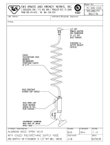
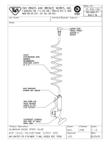
When removing the gun from the hose, hold the
hex end of the fluid tube (19) securely to avoid
loosening the fluid tube from the gun body.
Refer to Fig. 6, page 13.
SERVICE NOTES:
WARNING
SKIN INJECTION HAZARD
To reduce the risk of a serious injury,
including fluid injection, if fluid continues
to flow after the trigger is released,
service the gun immediately as instructed below.
Do not use the gun until the problem is corrected.
1. The numbers in parentheses in the text refer to
reference numbers in the drawings.
2. If the fluid continues to flow after the trigger is
released, the gun valve may need adjustment, be
obstructed or damaged, or the valve stem (24),
seat (26), or seal (3) may be worn or damaged.
See Fig. 4, page 11.
a. Adjust the valve or the spring tension as
instructed on page 9.
b. Replace the valve seal, stem, or seat as
instructed on page 10.
c. To inspect the valve for obstruction or damage,
disassemble the gun as instructed on page 11.
Clean and inspect the parts. Replace any worn
or damaged parts and reassemble the gun as
instructed on page 11.
3. Follow the torque, sealant and lubrication notes for
your gun model number.
4. The following repair kits are available:
Gun
Model
Repair
Kit
Description
235627 235658* 6.5 needle, seat, urethane
seal
235875 PTFE seal, o-rings only
235869 20 needle, seat, urethane
seal
237596 7.5 carbide needle, seat,
urethane seal
235628 235829* Carbide ball seat, ure-
thane seal
235875 PTFE and CV75 seal, o-
rings only
243775 237596* 7.5 carbide needle, seat,
urethane seal
235875 PTFE seal, o-rings only
237607 237596* 7.5 carbide needle, seat,
urethane seal
235875 PTFE seal, o-rings only
235869 20 SST needle, seat, ure-
thane seal
237649 237596* 7.5 carbide needle, seat,
urethane seal
* These are the standard Repair Kits for the gun
models. The other kits listed are optional.
NOTE: The fluid flow rates of guns using Repair Kits
235658 and 237596 are similar. Kit 235869 will provide
increased fluid flow. Kits 235658 and 235869 should
not be used to dispense abrasive fluids.
308253 9
Service
Adjusting the Valve
The trigger travel and corresponding valve opening are
factory set to 1 inch (25.4 mm). To adjust this setting,
follow the procedure below.
WARNING
SKIN INJECTION HAZARD
To reduce the risk of a serious injury,
including fluid injection, follow the Pres-
sure Relief Procedure on page 6
whenever you are instructed to relieve the
pressure.
1. Relieve the pressure in the system.
2. Disconnect the gun from the hose.
3. Using a 5/16 in. wrench, loosen the stem nut (1)
and spring housing (28). See Fig. 4, page 11.
4. Insert a 1/8 hex allen wrench through the hole in
the spring adjustment screw (21) and into the
spring housing (28).
5. Turn the spring housing (28) and stem nut (1) to
change the trigger travel and the size of the valve
opening.
6. Tighten the stem nut (1) to set the adjustment.
7. Adjust the spring adjustment screw (21) to the
desired trigger pull force.
Adjusting the Spring Tension
WARNING
SKIN INJECTION HAZARD
To reduce the risk of a serious injury,
including fluid injection, follow the Pres-
sure Relief Procedure on page 6
whenever you are instructed to relieve the
pressure.
1. Relieve the pressure in the system.
2. Disconnect the gun from the hose.
3. Turn the spring adjustment screw (21) as needed
until the spring force is adjusted to close the valve.
Refer to Fig. 4, page 11.
10 308253
Service
Valve Stem and Seal Service
If fluid leaks past the v-block seal (3), the v-block seal
or valve stem (24) may be worn or damaged. To
replace the seal or valve stem, follow the procedure
below.
WARNING
SKIN INJECTION HAZARD
To reduce the risk of a serious injury,
including fluid injection, follow the Pres-
sure Relief Procedure on page 6
whenever you are instructed to relieve the
pressure.
1. Relieve the pressure in the system.
2. Disconnect the gun from the hose.
3. Unscrew the spring retainer (21) and remove the
spring (4). See Fig. 4.
4. Unscrew the spring housing (28) with a 1/8 inch
hex allen wrench.
5. Unscrew the valve seat nut (26).
6. Remove the adjustment bracket (20) and stem nut
(1) from the stem.
7. Remove the valve stem (24).
8. Remove the seal retainer (27) and seal (3).
Replace the seal.
9. Secure the gun body (17) in an assembly fixture.
10. Lubricate the v-block seal (3) and install it into the
gun body (17) with the lips of the seal facing into
the housing.
11. Lubricate the seal retainer (27). Torque the seal
retainer into the gun body (17) to:
Models 235627, 237607, and 237649: 50–60
in-lbs (5.6–6.8 Nm).
Models 235628 and 243775: 100–125 in-lbs
(11.3–14.1 Nm).
12. Lubricate the valve stem threads (24) and install it
into the gun body (17). Thread the stem assembly
through the v-block seal (3).
CAUTION
Installing the valve stem (24) without turning it clock-
wise could damage the v-block seal and result in
fluid leakage.
13. Thread the nut (1) all the way onto the valve stem
(24).
14. Install the adjustment bracket (20) and spring
housing (28) onto the valve stem (24).
15. Lubricate the threads and o-ring sealing surface on
the valve seat nut (26). Torque the valve seat nut
into the gun body (17) to:
Models 235627, 237607, and 237649: 70–80
in-lbs (7.9–9.0 Nm).
Models 235628 and 243775: 100–125 in-lbs
(11.3–14.1 Nm).
16. Lubricate the spring (4) and spring retainer threads
(21) and install them in the gun body (17).
17. Insert a 1/8 inch hex allen wrench through the
spring retainer (21) and into the spring housing
(28). Adjust the trigger travel and valve opening to
the desired position.
18. Using a 5/16 inch wrench, tighten the stem nut (1)
to set the adjustment.
19. Adjust the spring adjustment screw (21) to the
desired trigger pull force.
308253 11
Service
NOTES:
Torque to 6–10 in-lbs (0.68–1.13 Nm)
Models 235627, 237607, & 237649: Torque to 70–80 in-lbs
(7.9–9.0 Nm)
Models 235628 and 243775: Torque to 100–125 in-lbs
(11.3–14.1 Nm)
Apply lithium base grease to threads
Apply lithium base grease
Models 235627, 237607, & 237649: Torque to 50–60 in-lbs
(5.6–6.8 Nm)
Models 235628 and 243775: Torque to 100–125 in-lbs
(11.3–14.1 Nm)
Models 235627, 237607, and 237649
Models 235628 and 243775
A
C
E
F
H
*
04809A
26
24
21
4
28
27
3
1
20
E
E
C
E
E
H
F
Fig. 4
F
A
24*
E
17
42
Complete Disassembly and Assembly
of the Gun
WARNING
SKIN INJECTION HAZARD
To reduce the risk of a serious injury,
including fluid injection, follow the Pres-
sure Relief Procedure on page 6
whenever you are instructed to relieve the
pressure.
Disassembly
1. Follow steps 1 to 7 under Valve Stem and Seal
Service. Be sure to relieve the system pressure
before beginning to service the gun.
2. Remove the trigger retaining rings (8), rod (13),
and the trigger (29). See Fig. 6, page 13.
3. Models 235627 and 237607: unscrew the fluid
tube (19) from the gun body (17).
Models 235628 and 243775: unscrew the set-
screw (42), then unscrew the fluid tube (19) from
the gun body (17).
CAUTION
To avoid loosening the connections and damaging
the gun, grip the gun body (17), not the handle (14),
when removing the fluid tube (19).
4. Model 237649: if necessary for replacement of
parts, unscrew the inlet fitting (19) from the fluid
tube (18).
5. Remove the gun handle screws (9), gun handle
(14), trigger lock (15), ball (2) and spring (7).
6. Remove the seal retainer (27), seal (3), and
o-rings (5 and 6).
12 308253
Service
Complete Disassembly and Assembly
of the Gun (continued)
Assembly
1. Follow steps 9 to 11 on page 10.
2. Lubricate the o-rings (5 and 6) and install them into
the gun body.
3. Follow steps 12 to 14 on page 10.
4. Lubricate the trigger pivot holes (a) bracket guide
(b), and rod (13).
5. Install the trigger (29) with the rod (13) and retain-
ing rings (8).
6. Lubricate the thread and o-ring sealing surface on
the valve seat nut (26). Torque the valve seat nut
into the gun body (17) to:
Models 235627, 237607, and 237649: 70–80
in-lbs (7.9–9.0 Nm).
Models 235628 and 243775: 100–125 in-lbs
(11.3–14.1 Nm).
7. Lubricate the trigger lock housing area (c) and
apply low strength anaerobic sealant to the screws
(9). See Fig. 5.
8. Install the spring (7) into the gun body (17). Place
the ball (2) in the center of the spring.
9. Align the trigger lock detent (d) with the ball (2).
Compress the ball (2) and spring (7) with the
trigger lock (15) until the trigger lock is seated in
the housing.
10. While holding the trigger lock (15) in place, install
the gun handle (14). Secure the gun handle with
the screws (9). Torque the screws to 6–10 in-lbs
(7.9–9.0 Nm).
11. For model 237649, if the inlet fitting (19) and fluid
tube (18) were disassembled, apply pipe thread
sealant compound to the inlet fitting (19). Install
the inlet fitting into the fluid tube (18). Torque the
fitting to 110–130 in-lbs (12.4–14.7 Nm).
12. Install the fluid tube (19) through the gun handle
(14) and screw it into the gun body (17). Torque
the fluid tube (19) to:
Models 235627, 237607, and 237649: 50–60
in-lbs (5.6–6.8 Nm).
Models 235628 and 243775: 200–250 in-lbs
(22.6–28.2 Nm). Secure the fluid tube with the
setscrew (42), and torque the setscrew to 6–10
in-lbs (0.7–1.13 Nm).
CAUTION
To avoid loosening the connections and damaging the
gun, grip the gun body (17), not the handle (14), when
tightening the fluid tube (19).
13. Adjust the free travel of the trigger as instructed
under Adjusting the Valve, page 9.
14. Follow steps 15 to 19 on page 10 to finish assem-
bling the gun.
Fig. 5
01806
17 7 2 15
9
dc14
F
c
F
A
M
NOTES:
Torque to 6–10 in-lbs (0.68–1.13 Nm)
Apply lithium base grease
Apply low strength anaerobic sealant (blue)
A
F
M
308253 13
Service
NOTES:
Torque to 6–10 in-lbs (0.68–1.13 Nm)
Models 235627, 237607, & 237649: Torque to 70–80 in-lbs
(7.9–9.0 Nm)
Models 235628 and 243775: Torque to 100–125 in-lbs
(11.3–14.1 Nm)
Apply lithium base grease to threads
Apply lithium base grease
When removing fluid hose, use wrench on end of fluid tube (19)
hex to avoid loosening fluid tube (19)
Models 235627, 237607, & 237649: Torque to 50–60 in-lbs
(5.6–6.8 Nm)
Models 235628 and 243775: Torque to 100–125 in-lbs
(11.3–14.1 Nm)
Torque to 50–60 in-lbs (5.6–6.8 Nm)
Torque to 200–250 in-lbs (22.6–28.2 Nm)
Torque to 110–130 in-lbs (12.4–14.7 Nm). Use the hex end of
the fluid tube (18) to reach the swivel fitting (19) torque
Apply low strength anaerobic sealant (blue)
Apply pipe thread sealing compound to threads
Apply anti-seize lubricant to threads
Models 235627 and 237607
Model 235628
Model 237649
Model 243775
M
22
26
5
24
21
4
28
27
3
1
20
7
2
17
8
29
15
9
14
6
8
13
E
J
O
35
34
A
E
C
F
E
A
C
E
F
F
F
Fig. 6
b
a
F
F
F
F
G
G
H
F
E
E
H
A
F
*
24*
E
18
19
19*
19
N G
L
M
N
L
KG
J
J
K
O
05445A
42
14 308253
Parts
Models 235627 and 237607
Pistol Grip Flow Gun
22
*26
*5
*24
21
4
28
27
*3
*1
20
7
2
17
8
29
15
9
14
6
19
*8
*13
35
34
05446
308253 15
Parts
Model 235627
Pistol Grip Flow Gun
Ref.
No. Part No. Description Qty.
1* 100975 NUT, hex; No. 5–40 1
2 102233 BALL 1
3* 102921 SEAL, v-block; polyurethane 1
4 102924 SPRING, compression 1
5* 103338 O-RING; fluoroelastomer 1
6 112085 O-RING; fluoroelastomer 1
7 111902 SPRING, compression 1
8* 112410 RING, retaining 2
9 111904 SCREW, handle; flat head 2
13* 189055 ROD 1
14 188231 HANDLE, plastic 1
15 188232 LOCK, trigger 1
17 188239 HOUSING, fluid; aluminum 1
19 237724 TUBE, fluid, with adapter;
300 series stainless steel 1
20 188246 BRACKET, adjustment 1
21 188247 SCREW, spring adjustment 1
22 188253 NUT, nozzle 1
24* 188836 VALVE STEM; 17–4 PH stainless
steel 1
26* 188263 NUT, valve seat; 17–4 PH
stainless steel 1
27 188271 RETAINER, seal 1
28 188275 HOUSING, spring 1
29 237604 TRIGGER 1
34 188377 LABEL, warning 1
35 188378 LABEL, instruction 1
* These parts are included in Repair Kit 235658,
which may be purchased separately. See page 8
for complete Repair Kit list.
Replacement Instruction and Warning labels are
available at no cost.
Model 237607
Pistol Grip Flow Gun
Ref.
No. Part No. Description Qty.
1 100975 NUT, hex; No. 5–40 1
2 102233 BALL 1
3 102921 SEAL, v-block; polyurethane 1
4 102924 SPRING, compression 1
5 103338 O-RING; fluoroelastomer 1
6 112085 O-RING; fluoroelastomer 1
7 111902 SPRING, compression 1
8 112410 RING, retaining 2
9 111904 SCREW, handle; flat head 2
13 189055 ROD 1
14 188231 HANDLE, plastic 1
15 188232 LOCK, trigger 1
17 188239 HOUSING, fluid; aluminum 1
19 237724 TUBE, fluid, with adapter;
300 series stainless steel 1
20 188246 BRACKET, adjustment 1
21 188247 SCREW, spring adjustment 1
22 188253 NUT, nozzle 1
24 237576 VALVE STEM; carbide & 17–4
PH stainless steel 1
26 237577 NUT, valve seat; carbide & 17–4
PH stainless steel 1
27 188271 RETAINER, seal 1
28 188275 HOUSING, spring 1
29 237604 TRIGGER 1
34 188377 LABEL, warning 1
35 188378 LABEL, instruction 1
These parts are included in Repair Kit 237596,
which may be purchased separately. See page 8
for complete Repair Kit list.
Replacement Instruction and Warning labels are
available at no cost.
16 308253
Parts
Models 237649
Pistol Grip Flow Gun
04807
22
26
5
24
21
4
28
27
3
1
20
7
2
17
8
29
159
14
6
18
19
8
13
35
34
308253 17
Parts
Model 237649
Pistol Grip Flow Gun
Ref.
No. Part No. Description Qty.
1 100975 NUT, hex; No. 5–40 1
2 102233 BALL 1
3 102921 SEAL, v-block; polyurethane 1
4 102924 SPRING, compression 1
5 103338 O-RING; fluoroelastomer 1
6 112085 O-RING; fluoroelastomer 1
7 111902 SPRING, compression 1
8 112410 RING, retaining 2
9 111904 SCREW, handle; flat hd 2
13 189055 ROD 1
14 188231 HANDLE, plastic 1
15 188232 LOCK, trigger 1
17 188239 HOUSING, fluid; aluminum 1
18 237724 TUBE, fluid; with adapter;
300 series stainless steel 1
19 237637 FITTING, inlet, swivel; 1/4–18 npt;
316 stainless steel 1
Ref.
No. Part No. Description Qty.
20 188246 BRACKET, adjustment 1
21 188247 SCREW, spring adjustment 1
22 188253 NUT, nozzle 1
24 237576 VALVE STEM; carbide & 17–4
PH stainless steel 1
26 237577 NUT, valve seat; carbide & 17–4
PH stainless steel 1
27 188271 RETAINER, seal 1
28 188275 HOUSING, spring 1
29 237604 TRIGGER 1
34 188377 LABEL, warning 1
35 188378 LABEL, instruction 1
These parts are included in Repair Kit 237596,
which may be purchased separately. See page 8
for complete Repair Kit list.
Replacement Instruction and Warning labels are
available at no cost.
18 308253
Parts
Model 235628
Pistol Grip Flow Gun
05447A
22
*26
*24
*5
21
4
28
27
*3
*1
20
7
2
17
8
29
15
9
14
6
19
*8
*13
35
34
42
308253 19
Parts
Model 235628
Pistol Grip Flow Gun
Ref.
No. Part No. Description Qty.
1* 100975 NUT, hex; No. 5–40 1
2 102233 BALL; stainless steel 1
3* 102921 SEAL, v-block; polyurethane 1
4 102924 SPRING, compression 1
5* 102982 O-RING; PTFE 1
6 111316 O-RING; CV75 1
7 111902 SPRING, compression 1
8* 112410 RING, retaining 2
9 111904 SCREW, handle; flat hd 2
13* 189055 ROD 1
14 188231 HANDLE, plastic 1
15 188232 LOCK, trigger 1
17 188242 HOUSING, fluid; stainless steel 1
19 237941 TUBE, fluid, with adapter;
300 series stainless steel 1
Ref.
No. Part No. Description Qty.
20 188246 BRACKET, adjustment 1
21 188247 SCREW, spring adjustment 1
22 188253 NUT, nozzle 1
24* 236234 STEM, valve 1
26* 236235 NUT, seat 1
27 188271 RETAINER, seal 1
28 188275 HOUSING, spring 1
29 237604 TRIGGER 1
34 188377 LABEL, warning 1
35 188378 LABEL, instruction 1
42 120048 SETSCREW 1
* These parts are included in Repair Kit 235829,
which may be purchased separately. See page 8
for complete Repair Kit list.
Replacement Instruction and Warning labels are
available at no cost.
20 308253
Parts
Model 243775
Pistol Grip Flow Gun
05447A
22
*26
*24
*5
21
4
28
27
*3
*1
20
7
2
17
8
29
15
9
14
6
19
*8
*13
35
34
42
  • Page 1 1
  • Page 2 2
  • Page 3 3
  • Page 4 4
  • Page 5 5
  • Page 6 6
  • Page 7 7
  • Page 8 8
  • Page 9 9
  • Page 10 10
  • Page 11 11
  • Page 12 12
  • Page 13 13
  • Page 14 14
  • Page 15 15
  • Page 16 16
  • Page 17 17
  • Page 18 18
  • Page 19 19
  • Page 20 20
  • Page 21 21
  • Page 22 22

Graco 243775 User manual

Category
Power fine-spray systems
Type
User manual

Ask a question and I''ll find the answer in the document

Finding information in a document is now easier with AI