
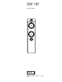
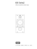
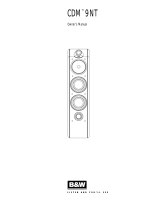
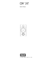
Owner’s Manual
CDM
™
7NT

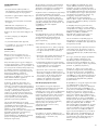
Figure 1
Figure 2
Figure 3
Figure 4
Figure 5
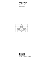
CDM
™
7NT Owner’s manual
English..........................................
1
Français
........................................2
Deutsch
.........................................3
Español
.........................................4
Português......................................6
Italiano .........................................7
Nederlands..................................8
Русский....................................10
"esky .........................................11
Polski..........................................12
Svenska......................................
13
Ελληνικά
.................................14
Dansk.........................................16
Slovenska navodila..................18
.........................................
19
........................................20
>0.5m
>0.5m
>1.5m
≈≈
≈
Figure 6

1
INTRODUCTION
Thank you for purchasing the B&W CDM™7NT
speakers.
Founded in 1966, B&W has always striven for
perfect sound reproduction in its products. To this
end, the company has invested heavily in
research and development in order to maintain
its position at the forefront of acoustic design.
Through the years, B&W has introduced many
advanced features and techniques. Although
many of these have been developed initially for
the more expensive models, our “waterfall”
design policy has seen them incorporated,
wherever possible, elsewhere in the product
range.
Features to be found in the CDM™NT Series
include cabinets with contoured edges to reduce
sound diffraction (the radiation of sound waves
from sharp edges that interfere with and blur the
direct sound from the drive units). An integral
part of the CDM™ range is the use of Kevlar®
cone bass/midrange drive units for lowest
coloration and maximum definition. The treble
units incorporate Nautilus™ tube technology,
which eliminates resonances behind the dome
diaphragm.
It is important to spend time setting up the
speakers, as care spent on the installation
process will reap the reward of many hours of
listening pleasure. Reading this manual fully will
help you obtain the best from your audio system.
B&W distributes to over 65 countries worldwide
and maintains a network of dedicated
distributors who will be able to help should you
have any problems your dealer cannot resolve.
Their mailing addresses can be found on the
web site or by calling B&W direct.
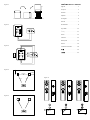
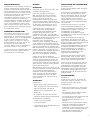
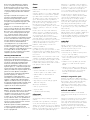
UNPACKING
(Figure 1)
• Fold the top carton flaps right back and invert
the carton and contents.
• Lift the carton clear of the contents.
• Remove the inner packing from the product.
• We suggest you retain the packing for future
use.
Check in the carton for:
• 4 Spike feet with lock nuts
• 2 Foam bungs
• 1 International warranty booklet
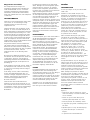
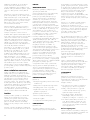
CONNECTIONS
(Figure 2 & 3)
All connections should be made with the
equipment switched off.
There are 2 pairs of terminals at the back of the
speaker which permit bi-wiring if desired. On
delivery, the separate pairs are connected
together with high-quality links for use with a
single 2-core cable. For single cable connection,
leave the links in place and use either pair of
terminals on the speaker.
Ensure the positive terminal on the speaker
(marked + and coloured red) is connected to the
positive output terminal of the amplifier and
negative (marked – and coloured black) to
negative. Incorrect connection can result in poor
imaging and loss of bass.
To bi-wire, remove the links by loosening the
terminal caps and use a separate 2-core cable
from the amplifier to each pair of terminals. This
can improve the resolution of low-frequency
detail. Observe the correct polarity as before.
When bi-wiring, incorrect connection can also
impair the frequency response.
The terminals accept bare wire. Always make
sure terminals are screwed down tight as
otherwise they may rattle.
Ask your dealer for advice when choosing
cable. Keep the total impedance below the
maximum recommended in specification and use
a low inductance cable to avoid attenuation of
the highest frequencies.
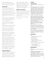
POSITIONING
(Figure 4)
Some experimentation with the position of the
speakers is well worthwhile to optimise the
interaction between them and the listening room.
However, as an initial guide:
• Do not fit the spike feet until you have found
the best position for the speakers.
• Place the speakers and the centre of the
listening area approximately at the corners of
an equilateral triangle.
• Keep the speakers at least 1.5m (5ft) apart to
maintain left-right stereo separation.
• Keep the speaker baffles at least 0.5m (20in)
clear of walls. Having the speakers too close
to walls increases the level of bass relative to
midrange and may give a boomy quality to
the sound.
Stray Magnetic Fields
The speaker drive units create stray magnetic
fields that extend beyond the boundaries of the
cabinet. We recommend you keep magnetically
sensitive articles (television and computer
screens, computer discs, audio and video tapes,
swipe cards and the like) at least 0.5m from the
speaker.
FINE TUNING
Before fine tuning, make sure that all the
connections in the installation are correct and
secure.
If the level bass is uneven with frequency it is
usually due to the excitation of resonance modes
in the room. Even small changes in the position
of the speakers or the listeners can have a
profound effect on how these resonances affect
the sound. Try mounting the speakers along a
different wall. Even large pieces of furniture can
have an effect.
Moving the speakers further from the walls will
reduce the general level of bass. Space behind
the speakers also helps to create an impression
of depth. Conversely, moving the speakers closer
to the walls will increase the level of bass.
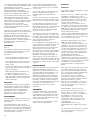
If you want to reduce the bass level without
moving the speakers further from the wall, fit the
foam bungs in the port tubes. (Figure 6)
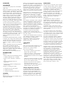
If the central image is poor, try moving the
speakers closer together or toeing them in so
they point just in front of the listeners. (Figure 5)
If the sound is too harsh, increase the amount of
soft furnishings in the room (for example us
heavier curtains), or reduce it if the sound is dull
and lifeless.
Test for flutter echoes by clapping your hands
and listening for rapid repetitions. Reduce them
by the use of irregular shaped surfaces such as
bookshelves and large pieces of furniture.
Ensure the speakers stand firmly on the floor.
Whenever possible fit the spike feet supplied
after you have optimised the positioning. These
are designed to pierce through carpets to the
floor surface. Initially, screw the lock nuts fully
onto the spikes and screw the spikes fully into
the threaded inserts in the base of the cabinet. If
the cabinet rocks, unscrew the two spikes that do
not touch the floor equally until the cabinet sits
firmly on the floor, and lock the nuts against the
cabinet. If there is no carpet and you wish to
avoid scratching the floor surface, use a
protective disc between the spike and the floor.
RUNNING-IN PERIOD
The performance of the speaker will change
subtly during the initial listening period. If the
speaker has been stored in a cold environment,
the damping compounds and suspension
materials of the drive units will take some time to
recover their correct mechanical properties. The
drive unit suspensions will also loosen up during
the first hours of use. The time taken for the
speaker to achieve its intended performance will
vary depending on previous storage conditions
and how it is used. As a guide, allow up to a
week for the temperature effects to stabilise and
15 hours of average use for the mechanical
parts to attain their intended design
characteristics.
AFTERCARE
The cabinet surface usually only requires dusting.
If you wish to use an aerosol cleaner, remove the
grille first buy gently pulling it away from the
cabinet. Spray onto the cleaning cloth, not
directly onto the cabinet. The grille fabric may
be cleaned with a normal clothes brush whilst
the grille is detached from the cabinet.
Avoid touching the drive units, especially the
tweeter, as damage may result.
Page is loading ...
Page is loading ...
Page is loading ...
Page is loading ...
Page is loading ...
Page is loading ...
Page is loading ...
Page is loading ...
Page is loading ...
Page is loading ...
Page is loading ...
Page is loading ...
Page is loading ...
Page is loading ...
Page is loading ...
Page is loading ...
Page is loading ...
Page is loading ...
Page is loading ...
Page is loading ...

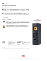
Technical Features
Description
Drive Units
Frequency Range
Frequency Response
Dispersion
Sensitivity
Harmonic distortion
Nominal Impedance
Crossover Frequencies
Recommended Amplifier Power Max.
Recommended Cable Impedance
Dimensions
Net Weight
CDM
™
7NT
Kevlar is a registered trademark of Dupont.
B&W Loudspeakers Ltd. reserves the right to amend details of the specification without notice in line with technical developments.
Copyright © B&W Loudspeakers Ltd. Printed in England.
B&W Loudspeakers Ltd, Meadow Road, Worthing, BN11 2RX England
Tel: +44 (0) 1903 524801 Fax: +44 (0) 1903 524725 http://www.bwspeakers.com
Free-mounted Nautilus™ tweeter
Kevlar® brand fibre cone bass/midrange
Paper/Kevlar® cone bass
Flowport™
2
1
/2 -way vented-box system
1x ø165mm (6.5 in) Paper/Kevlar® cone bass
1x ø165mm (6.5 in) woven Kevlar® cone bass/midrange
1x ø25mm (1 in) alloy dome high-frequency
-6dB at 30Hz and 30kHz
40Hz – 25kHz ±3dB on reference axis
Within 2dB of reference response
Horizontal: over 40˚ arc
Vertical: over 10˚ arc
90dB spl (2.83V, 1m)
2nd and 3rd harmonics (90dB, 1m)
<0.5% – 20kHz (3
rd
harmonic <0.2% 150Hz – 20kHz)
8Ω (minimum 4.6Ω)
150Hz, 4kHz
50W – 150W into 8Ω on unclipped programme
0.1Ω
Height: 950mm (37.4 in)
Width: 220mm (8.7 in)
Depth: 290mm (11.4 in)
22 kg (48 lb)
II08451 Issue 1
-
 1
1
-
 2
2
-
 3
3
-
 4
4
-
 5
5
-
 6
6
-
 7
7
-
 8
8
-
 9
9
-
 10
10
-
 11
11
-
 12
12
-
 13
13
-
 14
14
-
 15
15
-
 16
16
-
 17
17
-
 18
18
-
 19
19
-
 20
20
-
 21
21
-
 22
22
-
 23
23
-
 24
24


Ask a question and I''ll find the answer in the document
Finding information in a document is now easier with AI
in other languages
- italiano: B&W 7NT Manuale utente
- français: B&W 7NT Manuel utilisateur
- español: B&W 7NT Manual de usuario
- Deutsch: B&W 7NT Benutzerhandbuch
- русский: B&W 7NT Руководство пользователя
- Nederlands: B&W 7NT Handleiding
- português: B&W 7NT Manual do usuário
- dansk: B&W 7NT Brugermanual
- polski: B&W 7NT Instrukcja obsługi
- čeština: B&W 7NT Uživatelský manuál
- svenska: B&W 7NT Användarmanual
Related papers
-
 Bowers & Wilkins 600 Series2 Owner's manual
-
 Bowers & Wilkins CDM 9NT User manual
-
B&W CDM 1 SE User manual
-
 Bowers & Wilkins CDM CNT Owner's manual
-
 Bowers & Wilkins CM6 User manual
-
 Bowers & Wilkins CM2 Owner's manual
-
 Bowers & Wilkins CDM7 SE User manual
-
 Bowers & Wilkins CDM 1NT Owner's manual
-
 Bowers & Wilkins CC6 S2 User manual
-
 Bowers & Wilkins CDM CSE User manual


Other documents
-
 Bowers & Wilkins WM 2 User manual
-
Zephyr ZVO-E30AG Recirculating Kit Manual
-
 Bowers & Wilkins DM603 User manual
-
Bowers Wilkins 684 User manual
-
 Bowers & Wilkins DM604 User manual
-
Sony SS-M9ED User manual
-
 Bowers & Wilkins 803 User manual
-
Focal Aria 906 Prime Walnut User manual
-
Bose MediaMate® computer speakers Owner's manual
-
CABASSE Minorca MC40 User manual


