Page is loading ...

The Pipe/Tube Notcher is designed to notch pipe
and tubing at angles ranging from 45˚ to 90˚, and
handle a round workpiece from
3
⁄4" to 2
1
⁄8" outside
diameter (O.D.) using your drill press, mill or hand
drill. The stroke of the spindle is 3
3
⁄4" and accepts
hole saws that are threaded for
1
⁄2" and
5
⁄8" mount-
ing holes. A degree scale, workpiece clamp and
adjustable mounting base round out the items that
come with your new notcher.
The notcher comes from the factory packed in
the box with the spindle inverted. Before use,
the spindle will need to be removed and turned
around, as described below.
1. Pull the pin as shown in Figure 1 and extract
the spindle.
2. Remove the
5
⁄8" adapter and washer from the
spindle.
3. Insert the threaded end into the bracket.
4. Align the holes in the side of the spindle and
bracket and insert the pin.
MODEL G8686
PIPE/TUBE NOTCHER
INSTRUCTION SHEET
Figure 1. Pulling the pin.
COPYRIGHT © AUGUST, 2005 BY GRIZZLY INDUSTRIAL, INC.
WARNING: NO PORTION OF THIS MANUAL MAY BE REPRODUCED IN ANY SHAPE
OR FORM WITHOUT THE WRITTEN APPROVAL OF GRIZZLY INDUSTRIAL, INC.
#
DD7498 PRINTED IN CHINA
Figure 2. Aligning holes during assembly.
Specifications
Maximum Tube Capacity .................................. 2"
Maximum Hole Saw ......................................
2
3
⁄4"
Hole Saw Threads ........................
1
⁄2"-20 &
5
⁄8"-18
Spindle Stroke ...............................................
3
3
⁄4"

Figure 4. Ready to mount the hole saw.
Figure 3. Square the base to the jig.
The jig must be positioned squarely when used
on a drill press. The base supports the jig with a
bracket that is secured with 2 hex bolts, that when
loosened, allow it to pivot in 2 directions. For now
,
loosen the bolt as in
Figure 3, and rotate the base
so it is roughly square to the jig and tighten the
bolt.
Hole saws are attached by threading them onto
the jig spindle
. In some setups it may be an
advantage to remove the spindle support bracket
to make it easier to change out or install a hole
saw. To do this, do these steps:
1. Remove the 2 hex bolts located on the back
of the jig which secure the spindle support to
the jig as in
Figure 4.
2. Place the included washer onto the spindle
and screw the hole saw on by hand. If need-
ed, use the
5
⁄8" thread adapter.
3. Use a 16mm or adjustable end wrench to
hold the spindle and tighten the
hole saw.
The pin will hold the spindle when the jig is
mounted to a drill press or vise.
4. Place the bracket back on the jig and attach
loosely with the hex bolts. Make sure the p
in
is inserted through the bracket and spindle.
5. Place a workpiece into the strap clamp as in
Figure 4. Slide the bracket until the hole saw
almost touches the workpiece. Tighten the
hex bolts to secure the bracket.
Note: We recommend that the height of the
bracket be adjusted so the hole saw is
as close as it can be to the workpiece
without touching. This will help minimize
flex in
the jig.
Read the drill press man-
ual and be familiar with
the drill press before
using the pipe/tube
notcher. This manual is
not a replacement for the
drill press manual and is
to be used in conjunction
with it.

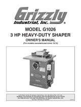
Figure 4. Mounting the jig to a drill press using
a strap clamp in one location and a bolt with a t-
nut in another location.
There are many w
ays to clamp the jig to a work
table on the drill press. Ultimately, it is important
to make sure that it is secure enough so it won't
twist or come off of the table during use. We rec
-
ommend that the jig be secured to the drill press
work table at 2 points as in
Figure 4. It is also
important to verify that the spindle of your drill
press is perpendicular to the worktable. Please
see the manual that came with your drill press
before proceeding further.
To setup the notching jig on the worktable of
your drill press, do these steps:
1. Place the jig on the work table of the drill
press, and lift or lower the table so that the
top of the jigs spindle is
1
⁄2" lower than the
drill chuck. This should be done with the pin
installed through the bracket and spindle.
2. Open the jaws to the drill chuck and lower it
onto the jig spindle.
3. Loosen the 2 hex bolts that attach the base to
the jig.
4. Locate the flats on the jig spindle and careful-
ly align them with the jaws on the drill chuck.
Tighten the jaws on the drill chuck. Failure
to clamp the flats properly may result in the
spindle coming loose in the drill chuck which
will damage drill chuck and the flats.
5. Secure the base of the notching jig to the top
of the drill press worktable with bolts, strap
clamps or C-clamps.
6. Rotate the drill chuck by hand to test how
easily the whole assembly turns. If it won't
turn or, if it takes a lot of effort to turn it, find
the reason. Use the following list to remedy
this problem.
a) Double check that the spindle is square to the
table.
b) Loosen the 2 hex bolts on the jig base and
rotate the spindle. Tighten the hex bolts and
test again.
c) Loosen the bolts/clamps that secure the
base to the work table and turn the spindle.
Retighten the bolts/clamps and test again.
Operation
For cutting steel pipe and tubing we recommend
bi-metal hole saws. These can be operated at up
to 500 RPM for most diameters and should be
operated at higher speeds for thin wall tubing.
Before operating the notcher, make sure that the
jig is secure, the workpiece is clamped solidly and
in the correct place, and that the drill chuck turns
freely.
We recommend using cutting fluid to extend the
life of the hole saw.
Before turning the drill press or hand drill ON
,
remove the pin from the spindle bracket and
spindle.
During operation it is necessary to oil the spindle
bushings. We recommend 10 wt. non-detergent
oil. A few drops applied to the spindle shaft above
the bushings before using the notching jig will be
adequate but if the jig is to be used for long peri
-
ods at a time oil should be applied several times
per hour.
Securing Points

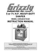
G8686 Parts Breakdown and List
Ref # Part # Description
1 G8686001 CLAMP ASSEMBLY
2 G8686002 HANDLE/CLAMP SCREW
3 G8686003 5⁄8" HOLESAW ADPT.
4 G8686004 5⁄8" HOLESAW WASHER
5 G8686005 BUSHING
6 G8686006 SPINDLE SUPPORT
7 G8686007 SPINDLE
8 G8686008 RIVET
9 G8686009 LABEL
Ref # Part # Description
10 PB09M HEX BOLT M8-1.25 X 20
11 PW10M WASHER M8
12 G8686012 ANGLE INDICATOR
13 G8686013 BODY
14 G8686014 LOCKING PIN
15 G8686015 ADJ. PLATE
16 G8686016 MOUNTING PLATE
17 PB07M HEX BOLT M8-1.25 X 25
/