Page is loading ...

For questions or help with this product contact Tech Support at (570) 546-9663 or techsupport@grizzly.com
MODEL T10809
WOOD LATHE CHUCK SET
INSTRUCTIONS
COPYRIGHT © DECEMBER, 2013 BY GRIZZLY INDUSTRIAL, INC.
NO PORTION OF THIS MANUAL MAY BE REPRODUCED IN ANY SHAPE
OR FORM WITHOUT THE WRITTEN APPROVAL OF GRIZZLY INDUSTRIAL, INC.
#TS16160 PRINTED IN CHINA
Introduction
The T10809 3
3
⁄4" Wood Lathe Chuck Set includes
a scroll chuck with four self-centering bottom jaws
and five top jaw sets to provide a variety of grip-
ping needs for your wood turning projects.
Specifications
Chuck Body Diameter ...................................3
3
⁄4"
Chuck Bore ...........................................1" x 8 TPI
Outside Grip Range:
— #1 Step Jaws ............................
3
⁄32"– 1
3
⁄8"
— #2 Round Jaws ......................... 1
1
⁄4"–2
1
⁄2"
— #3 Round Jaws ............................ 3"–4
1
⁄4"
— Pin Jaws ......................................
3
⁄8"–1
3
⁄4"
Inside Grip Range:
— #1 Step Jaws (Upper Step) .............
3
⁄4"–2"
— #1 Step Jaws (Lower Step) .......1
1
⁄2"–2
7
⁄8"
— #2 Round Jaws ......................... 1
3
⁄4"–3
1
⁄8"
— #3 Round Jaws .........................3
1
⁄2"–4
7
⁄8"
— Pin Jaws ....................................... 1"–2
3
⁄8"
Flat Jaws Maximum Outside Diameter .........5
1
⁄8"
Flat Jaws Minimum Inside Diameter .............2
7
⁄8"
Woodworm Required Hole ..................
5
⁄16" x 1
1
⁄4"
A
B
C
D
E
F
H
G
I
J
K
L
M
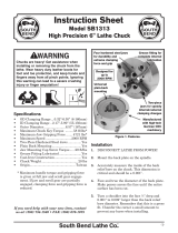
Inventory
Description: Qty
A. T-Handle Hex Wrench 4mm ....................... 1
B. Lathe Chuck Key 8mm Chrome ................. 1
C. Woodworm Screw ...................................... 1
D. Chuck Body ................................................ 1
E. #2 Round Jaws ........................................... 4
F. Pin Jaws ..................................................... 4
G. Grip Studs 18mm, M6-1 x 6 ....................... 8
H. Flat Jaws .................................................... 4
I. #1 Step Jaws .............................................. 4
J. Grip Studs 13mm, M6-1 x 6 ....................... 8
K. Flat Head Cap Screws M5-.8 x 8 ............... 8
L. #3 Round Jaws ........................................... 4
M. Hex Wrench 4mm ....................................... 1
To prevent personal injury, always under-
stand and follow all safety instructions in
your wood lathe owner's manual.

-2-
Model T10809 Wood Lathe Chuck Set
Serious injury or death can occur from getting entangled in, crushed between, or struck
by rotating parts on a lathe! Rotating workpieces can come loose and strike operator or
bystanders with deadly force if they are improperly secured, rotated too fast, or are not strong
enough for the rotational forces required for turning. Improper tool setup or usage can cause
tool kickback or grabbing, resulting in impact injury or entanglement. To reduce the risk of
operator (or bystander) injury or death, anyone operating this machine MUST completely heed
the hazards and warnings below.
WEAR PROPER PPE. Always wear a face shield
and safety glasses when operating lathe. Do not
wear gloves, necktie or loose clothing. Keep long
hair away from rotating spindle.
USE CORRECT SPEEDS. Select correct spindle
speed for workpiece size, type, shape, and
condition. Use low speeds when roughing or when
turning large, long, or non-concentric workpieces.
Allow spindle to reach full speed before turning.
AVOID TOOL KICKBACK. This occurs when
turning tool is grabbed or ejected from workpiece
with great force. Commonly caused by poor
workpiece selection/preparation, improper tool
usage, or improper machine setup or tool rest
adjustment.
SAFELY PERFORM ROUGHING. Use correct
tool. Take light cuts, use low speeds, and firmly
support tool with both hands.
USE SHARP TOOLS. Sharp tools cut with
less resistance than dull tools. Using dull tools
increases the risk of tool kickback or grabbing.
SAFELY STOPPING ROTATION. Always allow
rotating workpiece to stop on its own. Never put
hands or another object on workpiece to stop it.
SAFELY MEASURE WORKPIECE. Only mea-
sure mounted workpiece after it has completely
stopped. Trying to measure a spinning workpiece
increases entanglement risk.
SANDING/POLISHING. To reduce entanglement
risk, remove tool rest before sanding. Never
completely wrap sandpaper around workpiece.
VERIFY WORKPIECE INTEGRITY. Verify each
workpiece is free of knots, splits, nails, or foreign
material to ensure it can safely rotate on spindle
without breaking apart or causing tool kickback.
PROPERLY PREPARE WORKPIECE.
Before mounting, cut off waste portions to
balance workpiece for safe rotation and removal
of large edges that can catch on tooling.
SECURE LOCKS. Verify tool rest, headstock,
and tailstock are secure before turning lathe ON.
SECURE WORKPIECE. Use proven setup tech-
niques and always verify workpiece (and centers/
tooling holding workpiece) are well-secured before
starting lathe. Only use high-quality fasteners with
non-tapered heads for faceplate attachment.
ADJUST TOOL SUPPORT. An improperly sup-
ported tool may be grabbed or ejected. Adjust tool
rest approximately
1
⁄4" away from workpiece and
1
⁄8" above workpiece center line to provide proper
support for turning tool. Firmly hold turning tool
with both hands against tool rest.
REMOVE ADJUSTMENT TOOLS. Remove all
chuck keys, wrenches, and adjustment tools
before turning lathe ON. These items can become
deadly projectiles when spindle is started.
CHECK CLEARANCES. Before starting spindle,
verify workpiece has adequate clearance by
hand-rotating it through its entire range of motion.
TEST NEW SETUPS. Test each new setup by
starting spindle rotation at lowest speed and
standing to side of lathe until workpiece reaches
full speed and you can verify safe rotation.
Safety for Wood Lathes

Model T10809 Wood Lathe Chuck Set
-3-
Safety for Chucks
ENTANGLEMENT. Entanglement with a rotat-
ing chuck can lead to death, amputation, broken
bones, or other serious injury. Never attempt to
slow or stop the lathe chuck by hand, and always
roll up long sleeves, tie back long hair, and remove
any jewelry or loose apparel BEFORE operating.
CHUCK SPEED RATING. Excessive spindle
speeds greatly increase the risk of the workpiece
or chuck being thrown from the machine with
deadly force. Never use spindle speeds faster than
the safe limits of your chuck and workpiece.
USING CORRECT EQUIPMENT. Many
workpieces can only be safely turned in a lathe if
additional support equipment, such as a tailstock
center, is used. If the operation is too hazardous
to be completed with the lathe or existing equip-
ment, the operator must have enough experience
to know when to use a different machine or find a
safer way.
TRAINED OPERATORS ONLY. Using a chuck
incorrectly can result in workpieces coming
loose at high speeds and striking the operator or
bystanders with deadly force. To reduce the risk of
this hazard, read and understand this document
and seek additional training from an experienced
chuck user before using a chuck.
CHUCK CAPACITY. Avoid exceeding the capac-
ity of the chuck by clamping an oversized work-
piece. If the workpiece is too large to safely clamp
with the chuck, use a faceplate or a larger chuck
if possible. Otherwise, the workpiece could be
thrown from the lathe during operation, resulting in
serious impact injury or death.
CLAMPING FORCE. Inadequate clamping force
can lead to the workpiece being thrown from the
chuck and striking the operator or bystanders.
Maximum clamping force is achieved when the
chuck is properly maintained and lubricated, all
jaws are fully engaged with the workpiece, and
the maximum chuck clamping diameter is not
exceeded.
PROPER MAINTENANCE. All chucks must be
properly maintained and lubricated to achieve
maximum clamping force and withstand the rigors
of centrifugal force. To reduce the risk of a thrown
workpiece, follow all maintenance intervals and
instructions in this document.
DISCONNECT POWER. Serious entanglement or
impact injuries could occur if the lathe is started
while you are adjusting, servicing, or installing the
chuck. Always disconnect the lathe from power
before performing these procedures.
TOP JAW TYPES. Mixing top jaw types will create
an unbalanced and off-center load that could fly
from the lathe and cause personal injury or prop-
erty damage. Use all four top jaws of the same
type when securing workpiece.
POWER TOOLS. Do not use power tools on cap
screws or grip studs, which can easily damage the
threads and cause the component to fail during
operation. A workpiece or chuck component not
properly secured can fly off during operation and
cause serious personal injury.
TENON/RECESS SIZE. Size the tenon or recess
properly and choose the correct jaw configuration
so that there is the greatest possible amount of
surface contact between jaws and workpiece. The
greater the surface contact, the greater the grip-
ping power!
FLAT JAWS. Flat jaws (or cole jaws) provide the
least gripping power of the jaw types. Always use
slow speeds when using flat jaws.
SAFETY SET SCREW. The safety set screw
under bottom jaw #4 prevents the jaws from mov-
ing beyond safe engagement with the scroll gear.
If this should happen, the jaws and workpiece
could fly off the chuck during operation resulting
in serious personal injury to operator or bystand-
ers. Always make sure this set screw is properly
installed and tightened when using the chuck.

-4-
Model T10809 Wood Lathe Chuck Set
Mounting Jaws
1. Clean top and bottom jaws with mineral spir-
its. When dry, apply a thin coat of ISO 32 or
equivalent oil to the mating surfaces.
2. Place top jaws on bottom jaws so alignment
rings (see example below) fit into alignment
slots and screw holes are aligned.
Note: Make sure stamped numbers of chuck
jaw guide, bottom jaw, and top chuck corre-
spond with each other to ensure jaws safely
and evenly grip workpiece.
3. Apply a thin coat of ISO 32 or equivalent oil
to cap screw threads to prevent screws from
seizing under operational forces.
4. Thread the cap screws through the top jaws
into the bottom jaws and finger tighten them,
then back them off
1
⁄4 turn.
5. Use chuck key to converge jaws to the center
so they are evenly up against one another
and even in height.
6. Fully tighten cap screws—do not overtighten.
7. Check jaw alignment. They should be evenly
up against one another with no gaps and
even in height.
— If this is not the case, repeat this procedure
until they are.
Mounting Chuck
It is important that the chuck is properly mounted
to the lathe to ensure safe and accurate turning
(see the example below).
The safety set screw under bottom jaw #4
(see example below) prevents the jaws from
moving beyond safe engagement with the
scroll gear. Unsecured jaws could fly off the
chuck during operation resulting in serious
personal injury to operator or bystanders.
Always make sure this set screw is prop-
erly installed and tightened when using the
chuck.
Safety
Set Screw
Alignment
Ring
Alignment Slot
Jaw on Side
for Clarity

Model T10809 Wood Lathe Chuck Set
-5-
To mount the chuck onto the lathe:
1. DISCONNECT LATHE FROM POWER!
2. Thoroughly clean threads of spindle and
chuck bore with mineral spirits and a stiff
brush.
3. Properly mount top jaws onto bottom jaws.
4. To prevent chuck binding to spindle under
operational forces, apply a thin coat of ISO
32 or equivalent oil to spindle threads.
5. Thread chuck onto spindle and hand tighten.
It should screw on without binding or exces-
sive play.
6. Lock spindle in place.
7. Back chuck off slightly, then quickly rotate
chuck onto spindle. This will firmly seat the
chuck.
Indexing
The chuck back plate has indents and num-
bers for performing indexing operations. Indexing
allows the circumference of the workpiece to be
divided into equal segments.
An indexing arm (not included) is required to take
advantage of this feature. Research books and
the internet to better understand the process,
what is required, and how to perform indexing
operations.
Chuck Types
The best jaw type to use is the one that will pro-
vide the greatest contact between the jaw and the
workpiece—this provides the best gripping power!
Round Jaws
Round jaws (or dovetail jaws) are typically either
closed around a tenon (or foot) turned on the bot-
tom of a bowl, or they are expanded into a recess
cut into the workpiece. The tenon is later removed
with the workpiece mounted on the flat jaws.
A dowel workpiece can also be fed through the
center of the chuck and spindle bore, and gripped
with center surfaces of the jaw flats. As each
piece is turned and cut off, the dowel can be
advanced for the next piece.
The #2 round jaws have a slight dovetail profile. If
a matching profile is cut into the recess, the jaws
can expand with much greater gripping power.
#2 Round Jaws
#3 Round Jaws
The #3 round jaws can hold much larger
workpieces than the #2 round jaws and have
ridges that press into the wood for a better grip.
When mounting workpiece on jaws, do not
contact workpiece with the lower flat of
jaws. This provides better gripping power
and avoids any inconsistencies between
surfaces that would interfere with true rota-
tion.

-6-
Model T10809 Wood Lathe Chuck Set
Outside
Tenon Grip
Inside
Recess Grip
Round Jaws
(2 jaws removed for clarity)
#2 Round Jaws:
Outside Grip Range ............................. 1
1
⁄4"–2
1
⁄2"
Inside Grip Range ................................ 1
3
⁄4"–3
1
⁄8"
#3 Round Jaws:
Outside Grip Range ................................ 3"–4
1
⁄4"
Inside Grip Range ................................3
1
⁄2"–4
7
⁄8"
Pin Jaws
Pin jaws are typically used to expand into a deep
recess cut into a bowl-shaped workpiece for initial
roughing of the outside and tenon (or foot).
When used to grip the inside of a recess, the
advantage to pin jaws over step or round jaws is
that they offer a lot of surface area for gripping.
They also have ridges on the outside for greater
gripping power. The disadvantage is that the
recess must be fairly deep. However, this is usu-
ally cut into the waste portion of the workpiece
and removed later.
The smooth center surface of the pin jaws can
also grip externally around a small tenon on
objects such as Christmas ornaments, wooden
tops, lace bobbins, or other delicate work without
marring the workpiece.
Inside
Recess Grip
Small
Diameter
Workpiece
Pin Jaws
(2 jaws removed for clarity)
Outside Grip Range ...............................
3
⁄8"–1
3
⁄4"
Inside Grip Range ................................... 1"–2
3
⁄8"

Model T10809 Wood Lathe Chuck Set
-7-
Step Jaws
The step jaws have two outside profiles of differ-
ent circumferences designed to expand into the
recess cut into the workpiece. The surfaces of the
jaws have ridges that push into the wood which
increases the gripping power.
The center surfaces of the step jaws are ridged
and can grip a dowel-type workpiece from the
outside that is fed through the chuck and spindle
bore.
Basically, step jaws combine the capabilities of
the round jaws and the pin jaws, but are much
more versatile than either of those jaws alone.
Upper
Step
Lower
Step
Inside
Recess Grip
Outside Grip
Step Jaws
(2 jaws removed for clarity)
Outside Grip Range .............................
3
⁄32"– 1
3
⁄8"
Inside Grip Range:
— Upper Step ......................................
3
⁄4"–2"
— Lower Step ................................1
1
⁄2"–2
7
⁄8"
Flat Jaws (or Cole Jaws)
Used with included grip studs, flat jaws are pri-
marily used to finish the bottom of a bowl-type
workpiece (see examples below). The included
studs are 13 and 18mm in height and are rubber
coated to prevent marring. Use the stud set and
configuration that has the most surface contact
with the workpiece.
Flat Jaws
Grip
Stud
Grip
Stud
Workpiece
(Top View)
(Side View, Outside Grip)
(Side View, Inside Grip)
Grip
Stud
Flat Jaws Maximum Outside Diameter .........5
1
⁄8"
Flat Jaws Minimum Inside Diameter .............2
7
⁄8"

-8-
Model T10809 Wood Lathe Chuck Set
Woodworm Screw
The woodworm screw is typically used with the
#2 round jaw set for holding small items. Refer to
the illustration below for closing the round jaws
around the base of the screw.
Woodworm Screw
The woodworm screw has a very coarse 45°
thread that provides a positive grip in the wood.
Using the woodworm screw is an easy way to
mount a blank workpiece, but does not provide the
gripping power that the other jaws do. For heavy,
unbalanced workpieces or ones that require more
gripping power, use one of the jaw types or screw
the workpiece to a faceplate.
When using the woodworm screw, make sure the
workpiece is as round as possible, then drill a
5
⁄16"
x 1
1
⁄4" hole in the waste portion of the workpiece.
Thread the workpiece onto the screw until it is
seated firmly against the chuck.
Bottom Jaw Removal & Installation
If it is necessary to remove the bottom jaws for
maintenance or replacement, follow these steps
to ensure the jaws will safely and evenly grip
workpieces.
To remove the bottom jaws:
1. Remove top jaws.
2. Using chuck key, bring bottom jaws together
in center of chuck. This will provide access to
safety set screw.
3. Remove safety set screw under bottom jaw
#4 (see example below) and set it aside.
Safety
Set Screw
4. Insert chuck key and rotate it counterclock-
wise to move the bottom jaws away from
center of chuck.
5. Remove jaws one by one as they disengage
from the scroll gear.

Model T10809 Wood Lathe Chuck Set
-9-
To re-install the bottom jaws:
1. Clean bottom jaws and jaw guides with min-
eral spirits. When dry, apply a thin coat of ISO
32 or equivalent oil to the mating surfaces.
2. Make sure safety set screw is properly
installed in jaw guide #4.
3. Rotate chuck key clockwise until you see
the tip of scroll gear lead thread just begin to
enter jaw guide #1 (see below).
1
Scroll Gear
Lead Thread
Locations
May Vary
1
4. Insert bottom jaw #1 into jaw guide #1, and
hold jaw against scroll gear.
5. Rotate chuck key clockwise one turn to
engage tip of scroll gear lead thread with bot-
tom jaw. Pull the jaw; it should be locked into
jaw guide.
6. Install the remaining jaws in numerical order,
in the same manner. If installed correctly, the
jaws will converge evenly at center of chuck.
— If jaws do not converge evenly, remove
them. Make sure stamped numbers of
bottom jaws and jaw guides match, then
re-install jaws and make sure each one
engages with scroll gear lead thread during
its first rotation.
Maintenance
Clean and lubricate the chuck on a regular basis
to ensure the jaws move in and out evenly, can
be properly secured to the chuck, and provide a
solid grip.
Cleaning
Brush chips and dust off the chuck and jaws. Do
not use pressurized air that can drive the debris
farther into the chuck.
If resin builds up on the sliding surfaces making
the chuck difficult to operate, soak the chuck and
jaws for 30 minutes in mineral spirits with 10%
ISO 32 or equivalent oil added. Drain thoroughly
and allow to dry.
Lubrication
1. Apply a thin coat of ISO 32 or equivalent oil
to all outside surfaces of bottom and top jaws,
and chuck body.
2. Turn the chuck upside down and remove the
two Phillips head screws that secure back
plate, then remove back plate (see example
below).
Pinion Gears
Back
Plate
3. Add several drops of ISO 32 or equivalent oil
to pinion gears, then use chuck key to rotate
scroll gear back and forth to evenly distribute
the lubricant.
4. Replace the back plate before using chuck in
operations.

-10-
Model T10809 Wood Lathe Chuck Set
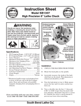
Parts
REF PART # DESCRIPTION REF PART # DESCRIPTION
1 PT10809001 FLAT HD CAP SCR M5-.8 X 12 12 PT10809012 STEP JAW #1 4-PC SET
2 PT10809002 SET SCREW M4-.7 X 6 CONE-PT 13 PT10809013 PIN JAW 4-PC SET
3 PT10809003 ROUND JAW #2 4-PC SET 14 PT10809014 ROUND JAW #3 4-PC SET
4 PT10809004 BOTTOM JAW 4-PC SET 15 PT10809015 FLAT JAW 4-PC SET
5 PT10809005 PINION GEAR 16 PT10809016 WOODWORM SCREW
6 PT10809006 CHUCK BODY 17 PT10809017 GRIP STUD M6-1 X 6, 18L 8-PC SET
7 PT10809007 THREADED LOCK PIN 18 PT10809018 HEX WRENCH 4MM
8 PT10809008 SCROLL GEAR 19 PT10809019 T-HANDLE HEX WRENCH 4MM
9 PT10809009 EXT RETAINING RING 48MM 20 PT10809020 LATHE CHUCK KEY 8MM CHROME
10 PT10809010 INDEXING BACK PLATE 21 PT10809021 GRIP STUD M6-1 X 6, 13L 8-PC SET
11 PT10809011 FLAT HD SCR M4-.7 X 8
Please Note: We do our best to stock replacement parts whenever possible, but we cannot guarantee that all parts shown here
are available for purchase. Call (800) 523-4777 or visit our online parts store at www.grizzly.com to check for availability.
1
2
3
4
5
6
7
8
9
10
11
12
13
14
15
16
17
18
19
20
21
/