
For more information, visit www.desatech.com
SAVE THIS BOOK
This book is valuable. In addition to instructing you
on how to install and maintain your appliance, it also
contains information that will enable you to obtain re-
placement parts or accessory items when needed. Keep
it with your other important papers.
-
place or for use with a vented gas log approved to ANS
Z21.60, Z21.84 or RGA 2-72 standards or for use with a vent-
free gas log heater approved to ANS Z21.11.2 standard.
etc.) should be contacted before installation to deter-
mine the need to obtain a permit.
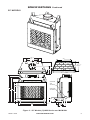
WOOD BURNING FIREPLACE
OWNER’S OPERATION AND INSTALLATION MANUAL
(V)GM36, (V)GM42 AND
(V)GM50 SERIES AND WCM-36G,
WCM-42G AND WCM-50G
WOOD BURNING MASONRY
FIREPLACES WITH INSULATION
ICC-ES #ESR-2542

www.desatech.com
122271-01B2
-
damage or loss of life. Refer to this manual for assis-
installer or local distributor.
TABLE OF CONTENTS
Safety .................................................................. 2
Specications ...................................................... 3
Fireplace Installation............................................ 6
Venting Installation .............................................. 8
Optional Gas Line Installation............................ 13
Brick Installation ................................................ 14
Glass Door Installation ...................................... 29
Operation and Maintenance Guidelines ............ 31
Technical Service............................................... 33
Replacement Parts ............................................ 33
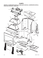
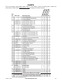
Parts ................................................................. 34
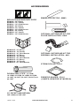
Accessories ....................................................... 37
SAFETY
or liquids in the vicinity of this
or any other appliance.
appliance should be located
furniture and draperies.
the appliance.
-
only. When processed wood fuel
stir the logs while they are burn-
been evaluated for the application
warnings and caution markings
on packaging prior to use.
used as a substitute for a furnace
supplemental heat only.
Before beginning the installation of the
fireplace, read these instructions through
completely.
• This DESA Heating, LLC replace and its
components are safe when installed ac-
cording to this installation manual. Unless
you use DESA Heating, LLC components,
which have been designed and tested for
the replace system, you may cause a re
hazard.
• The DESA Heating, LLC warranty will be
voided by and DESA Heating, LLC dis-
claims any responsibility for the following
actions.
a. Modification of the fireplace, com-
ponents, doors, air inlet system and
damper control.
b. Use of any component part not manu-
factured or approved by DESA Heat-
ing, LLC in combination with a DESA
Heating, LLC replace system.
Proper installation is the most important step
in ensuring safe and continuous operation
of the replace. Consult the local building
codes as to the particular requirements
concerned with the installation of all factory
built replaces.
the manufacturer's instructions
use with this insert.

www.desatech.com
122271-01B 3
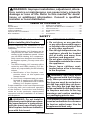
SPECIFICATIONS
29"
14
1
/
2
"
22
1
/
2
"
26
5
/
8
"
4
1
/
2
"
15
5
/
8
"
4
1
/
2
"
1"
58"
7
1
/
4
"
11"
15
1
/
4
"
3
1
/
2
"
9
1
/
2
"
10
1
/
2
"
67"
61"
49"
11"
7"
30"
1"
45
1
/
8
"
36"
OUTSIDE AIR
ACCESS
GAS LINE
ACCESS
36" HEARTH
1
5
/
16
"
19
13
/
16
"
(Ref.)
35
3
/
8
"
22"
18
3
/
8
"
Figure 1 - 36" Models (V)JM36 Series and WCM-36J

www.desatech.com
122271-01B4
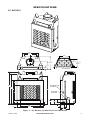
SPECIFICATIONS Continued
22
3
/
4
"
30
1
/
2
"
29"
4
3
/
8
"
15
3
/
4
"
5/8"
17
5
/
8
"
67"
61"
49"
7"
1"
30"
11 "
58"
42"
51
1
/
8
"
4
1
/
2
"
3
1
/
2
"
9
1
/
2
"
10
1
/
2
"
8
1
/
2
"
13"
17"
OUTSIDE
AIR
ACCESS
GAS LINE
ACCESS
23
13
/
16
"
(Ref.)
1
5
/
16
"
41
3
/
8
"
25"
22
1
/
2
"
42" HEARTH
Figure 2 - 42" Models (V)JM42 Series and WCM-42J

www.desatech.com
122271-01B 5
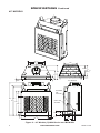
SPECIFICATIONS Continued
38
1
/
2
"
28
1
/
2
"
4
3
/
8
"
17
5
/
8
"
19
1
/
4
"
24"
49"
30"
11 "
61"
67"
58"
7"
1"
59"
50"
4
1
/
2
"
3
1
/
2
"
9
1
/
2
"
10
1
/
2
"
8
1
/
2
"
13"
17"
GAS LINE
ACCESS
OUTSIDE
AIR
ACCESS
23
13
/
16
"
(Ref.)
1
5
/
16
"
33"
49
3
/
8
"
22
1
/
2
"
50" HEARTH
Figure 3 - 50" Models (V)JM50 Series and WCM-50J

www.desatech.com
122271-01B6
FIREPLACE INSTALLATION
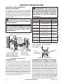
1. Frame opening for replace using dimen-
sions shown in Figures 4 and 5.
2. If replace is to be installed directly on
carpeting, tile (other than ceramic) or any
combustible material other than wood
ooring, replace must be installed upon
a metal or wood panel extending full width
and depth of replace.
3. Set replace directly in front of this open-
ing and slide unit back until nailing anges
touch side framing.
4. Check level of the replace and shim with
sheet metal if necessary.
5. Before securing fireplace to prepared
framing, ember protector (provided) must
be placed between hearth extension (not
supplied) and under bottom front edge of
replace to protect against glowing embers
falling through. If replace is to be installed
on a raised platform, a Z-type ember pro-
tector (not supplied) must be fabricated to
t your required platform height. Ember
protector should extend under replace a
minimum of 1
1
/
2
". Ember protector should
be made of galvanized sheet metal (28
gauge minimum to prevent corrosion.
6. Using screws or nails, secure replace to
framing through anges located on sides
of replace.
30.125"
59" (50" Models)
58.125"
67.125"
51.25" (42" Models)
45.25" (36" Models)
28.250" (36" Models)
Figure 4 - Framing Dimensions
71" (50" Models)
100" (50" Models)
65" (42" Models)
92" (42" Models)
86.5" (36" Models)
61" (36" Models)
Maintain 1
1
/
2
"
Clearance
at Sides and
Back of Fireplace
1
1
/2" Clearance
Not Required at
Nailing Flanges
Figure 5 - Corner Installation
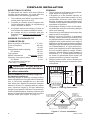
To determine the safest and most efcient
location for the replace, you must take into
consideration the following guidelines:
1. The location must allow for proper clear-
ances (see Figures 4 and 5).
2. Consider a location where replace will
not be affected by drafts, air conditioning
ducts, windows or doors.
3. A location that avoids cutting of joists or
roof rafters will make installation easier.
4. An outside air kit is available with this
replace (see Optional Outside Air Kit on
page 8).
Back and sides of replace 1
1
/
2
" min.*
Front of replace 48" min.
Floor** 0" min.
Perpendicular wall to opening 18" min.
36" Models 12" min.
Top spacers 0" min.
Mantel clearances
see Mantels, page 7
Chimney outer pipe surface 2" min.
36" Model 1" min.
* Not required at nailing anges
** See step 2 of Framing
-
quired air spaces with insulation
or other materials.
Residential Installation
Minimum height of chimney, measured from
base of replace to ue gas outlet of termina-
tion, is 16 feet for straight ue or a ue with
one elbow set. Maximum distance between
elbows is 6 feet. For systems with two elbow
sets, minimum height is 22 feet. Maximum
height of any system is 50 feet. This measure-
ment includes replace, chimney sections and
height of termination assembly at level of the
ue gas outlet (see Figure 15, page 11).

www.desatech.com
122271-01B 7
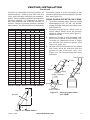
HEARTH ExTENSION
A hearth extension projecting a minimum of
20" in front of and a minimum of 12" beyond
each side of replace opening is required to
protect combustible oor construction in front
of replace. Fabricate a hearth extension
using a material which meets the following
specications: a layer of noncombustible,
inorganic material having a thermal conduc-
tivity of K=0.84 BTU IN/FT, HR. F (or less) at
1" thick. For example, if the material selected
has a K factor of 0.25, such as glass ber, the
following formula would apply:
0.25 x 1.0" = 0.30" thickness required
0.84
Thermal conductivity "K" of materials can be
obtained from manufacturer or supplier of
noncombustible material. If hearth extension
is to be covered, use noncombustible mate-
rial such as tile, slate, brick, concrete, metal,
glass, marble, stone, etc. Provide a means
to prevent hearth extension from shifting and
seal gap between replace frame and hearth
extension with a noncombustible material
(see Figure 6).
is to be installed only as shown
FIREPLACE INSTALLATION
Continued
Figure 6 - Hearth Extension
Seal Gap
Fireplace Front
Ember Protector
Fireplace Front
Raised Hearth
Fireplace Front
Elevated
Ember Protector
Ember Protector
Seal Gap
Hearth
Extension
A mantel may be installed if desired (see Figure
7). Woodwork such as wood trims, mantels or
any other combustible material projecting from
front face must not be placed within 12" (36"
Models) or 18" (42/50" Models) of replace
opening. Combustible materials above 12" (36"
Models) or 18" (42/50" Models) and projecting
more than 1
1
/
2
" from replace must not be
placed less than 15" (36" Models) or 21" (42/50"
Models) from the top opening of the replace
(NFPA STD 211, Sec. 7-3.3.3).
Mantels or any other combustible material
also may come up to side edge of black metal
face of replace as long as projections from
front face fall within limit shown in Figure 7.
12
1
/
4
" Ref.
6"
Ref.
15" Min. (36" Models)
21" Min. (42/50"
Models)
12" Min.
(36" Models)
18" Min.
(42/50"
Models)
1
1
/
2
" Max.
3" Nom.
33°
Combustible
Material
Safe
Zone for
Projection of
Combustible
Materials
Fireplace Opening
Upper
Section of
Fireplace
Figure 7 - Mantel Clearances to
Combustible Material
FIREBOX
SAFE ZONE
Top View of Fireplace
3" Max.
4.5"
Min. to
Perpendicular
Side Wall
7.75" (36" Models)
11.5" (42/50" Models)
33°
Combustible
Material Must
Not Overlap
Front Face
12" - 36" Models
18" - 42/50" Models

www.desatech.com
122271-01B8
Figure 9 - Lineal Gain
PART NO. GAIN
Georgian Fireplace 66
1
/
2
"
12-12DM
12-12HT
Pipe Section 10
5
/
8
"
18-12DM
18-12HT
Pipe Section 16
5
/
8
"
24-12DM
24-12HT
Pipe Section 23
5
/
8
"
36-12DM
36-12HT
Pipe Section 34
5
/
8
"
48-12DM
48-12HT
Pipe Section 46
5
/
8
"
RLT-12D
RLT-12HT
Round Termination 7
3
/
4
"
*
STL-12D
Square Chase-Top
with Slip Section
7
"
to 15
"
*
* The lineal gain for the terminations is mea-
sured to the ue gas outlet height.
Hemmed
End
12
3
/
8
"
Stainless
Inner Pipe
15" Galvanized
Outer Pipe
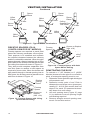
Each double wall chimney section consists of a
galvanized outer pipe, a stainless steel inner ue
pipe and a wire spacer. The pipe sections must
be assembled independently as the chimney is
installed. When connecting chimney directly to
the replace, the inner ue pipe section must
be installed rst with the lanced side up. The
outer pipe section can then be installed over
5 the ue pipe section with the hemmed end
up. Press down on each pipe section until the
lances securely engage the hem on the replace
starter. The wire will assure the proper spacing
between the inner and outer pipe sections.
Figure 8 - Outside Air Kit
Secure to Collars with Metal Tape,
Screws or Straps (Min. of 1/4" x 20"
in size)
Air Inlet
Location
Must Allow
For Bushes
or Snow
Vent Hood
Required for
Wall Installation
Air Inlet
Eyebrow
Vented Crawl Space
(Check Local Codes
Before Installing in a
Vented Crawl Space)
The DESA Heating, LLC chimney system
consists of 12", 18", 24", 36" and 48" snap-
lock, double-wall pipe segments, planned
for maximum adaptability to individual site
requirements. Actual lengths gained after
tting overlaps must be taken into consider-
ation (lineal gain) and are given in the lineal
gain chart (see Figure 9). Lineal Gain is the
actual measurable length of a part after two or
more parts are connected. For Canada, use
chimney parts designated "HT".
VENTING INSTALLATION
The installation of an outside air kit should
be performed during the rough framing of
the replace due to the nature of it's location.
Outside combustion air is accessed through
a vented crawl space (AK4F) or through a
sidewall (AK4).
inlet ducts shall not terminate
in attic space.
termination.
the collar around the chimney at
be obstructed. Never use blown
enclosure.

www.desatech.com
122271-01B 9
VENTING INSTALLATION
Continued
RISE
A B 12" 18" 24" 36" 48"
4
3
/
8
" 16
3
/
8
"
ELBOW SET ONLY
9
3
/
4
" 25
1
/
2
"
1
12
3
/
4
" 30
3
/
4
"
1
15" 34
3
/
4
"
1
18" 40"
1 1
21
1
/
4
" 46
1
/
4
"
1
23
3
/
4
" 49
1
/
4
"
1 1
27
3
/
4
" 56
3
/
4
"
1
30" 60
3
/
4
"
1 1
33" 66"
1
36" 71"
1 1
38
1
/
4
" 75"
2
41
1
/
4
" 80
1
/
4
"
1 1 1
45" 86
3
/
4
"
2
46
3
/
4
" 89
1
/
2
"
1 1 1
51" 97"
1 1
53
1
/
4
" 101"
2
56
1
/
4
" 106
1
/
4
"
2
59
1
/
4
" 111
1
/
2
"
1 1 1
61
3
/
4
" 115
1
/
2
"
1 2
64
3
/
4
" 120
3
/
4
"
1 2
68
1
/
4
" 127"
2 1
70" 130"
1 1 2
74
1
/
4
" 137
1
/
2
"
1 2 1
76
3
/
4
" 141
1
/
2
"
1 2 1
79
3
/
4
" 146
3
/
4
"
4
OFFSET CHART (22-50 FT. SYSTEM HEIGHT)
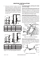
Figure 11 - Ceiling Support Pipe
12S-12DM
2" Min.
Straps
Straps
Straps
Straps
Detail A
Return Elbow
Detail B
Angle Firestop
See Detail A
See Detail B
Continue to assemble chimney sections as
outlined above, making sure that both the
inner and outer pipe sections are locked to-
gether. When installing double wall snap-lock
chimney together, it is important to assure
the joint between the chimney sections is
locked. Check by pulling chimney upward
after locking. The chimney will not come apart
Figure 10 - Elbow Offset
B
A
Screws
if properly locked. It is not necessary to add
screws to keep the chimney together (excep-
tion, see Figure 10).
1.
To achieve desired offset, you may install
combinations of 12", 18", 24", 36" and 48"
length of double wall pipe (see offset chart
and Figure 10).
2.
Chimney weight above offset rests on
return elbow. Straps must be securely
nailed to rafters or joists (see Figure 11,
details A and B).
3. Maximum length of pipe between sup-
ports (return elbow or 12S-12DM) is 6'
of angle run. Maximum of two 6' angle
run sections per chimney system (see
Figure 12, page 10).
4. All pipe connections between the offset
and return must be secured with two
screws on the outer pipe only (see
Figure 10). Do not penetrate the inner
stainless.

www.desatech.com
122271-01B10
VENTING INSTALLATION
Continued
Firestop spacers are required at each point
where the chimney penetrates a oor space.
Their purpose is to establish and maintain
the required clearance between the chimney
and the combustible materials. When the pipe
passes through a framed opening into a living
space above, the restop must be placed onto
the ceiling from below as shown in Figure 13.
They also provide complete separation from
one oor space to another or attic space as
required by most codes. When the double wall
pipe passes through a framed opening into an
attic space, the restop must be placed into an
attic oor as shown in Figure 14.
Figure 13 - Firestop Spacer with Living
Space Above Ceiling
Figure 14 - Firestop Spacer with Attic
Space Above Ceiling
Existing
Ceiling
Frame
Firestop
Spacer
Screws or
Staples
(Min. of 8)
Firestop
Spacer
Screws or Staples
(Min. of 8)
To maintain a 1" (36" Models) or 2" (42/50"
Models) clearance to the pipe on a roof with a
pitch, a rectangular opening must be cut.
1. Determine center point through which pipe
will penetrate roof.
2. Determine center point of roof. Pitch is
distance the roof drops over a given span,
usually 12". A 6/12 pitch means that roof
drops 6" for each 12" measured horizon-
tally down from roof rafters.
3. Use roof opening chart (Figure 15, page
11) to determine correct opening length
and ashing required.
4. Remove shingles around opening mea-
sured. Cut out this section.
Existing
Ceiling
Frame
Figure 12 - Typical Offset Terminations
Return
Elbow
Offset
Elbow
Return
Elbow
Offset
Elbow
6' Max.
6' Max.
6' Max.
6' Max.
6' Max.
6' Max.
Return
Elbow
Offset
Elbow
Offset
Elbow
Return
Elbow
A B C
Offset
Elbow
Ceiling
Support Pipe
12S-12DM
Return
Elbow

www.desatech.com
122271-01B 11
VENTING INSTALLATION
Continued
17" Min.
30" Min.
1" Min.
1" Min.
1" Min.
Opening "A"
Pitch Slope Opening
Flat 0° 17" V6F-10DM
0-6/12 26.6° 19" V6F-10DM
6/12-
12/12
45.0° 24" V12F-10DM
Pitch Slope Opening
Flat 0° 19.5" V6F-10DM
0-6/12 26.6° 22' V6F-10DM
6/12-12/12 45.0° 27" V12F-10DM
5. Add next sections of pipe until end
penetrates roof line. Check to see that
proper clearances are maintained. Extend
chimney by adding sections of double wall
pipe until pipe is minimum of 30" above
highest point of roof cutout. Termination
and chimney must extend a minimum of
36" above highest point where it passes
through roof.
19.5" Min.
30" Min.
2" Min.
2" Min.
2" Min.
Opening "A"
Figure 15 - Roof Opening Measurements
Nail Only
Outer
Perimeter
of Flashing
Storm Collar
Flashing
Cone
Underlap Shingles
at Bottom
Overlap
Shingles Top
and Sides Only
Figure 16 - Flashing Installation
Determine the ashing to be used with the roof
opening chart. Slide ashing over pipe until
base is at against roof. Replace as many
shingles as needed to cover exposed area
and ashing base. Secure in position by nail-
ing through shingles (see Figure 16). DO NOT
NAIL THROUGH FLASHING CONE.
When installing the ashing on a metal roof,
it is required that putty tape be used between
the ashing and the roof. The ashing must be
secured to the roof using #8 x 3/4" screws and
then sealed with roof coating to prevent leak-
age through the screw holes. A roof coating
must also be applied around the perimeter of
the ashing to provide a proper seal.
Place storm collar over pipe and slide down
until it is snug against the open edge of the
ashing (see Figure 17). Apply waterproof
caulk around the perimeter of the collar to
provide a proper seal.
Figure 17 - Storm Collar
Chimney
Pipe
Waterproof
Caulk
Storm
Collar
Flashing

www.desatech.com
122271-01B12
VENTING INSTALLATION
Continued
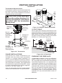
All ue gas outlet chimney terminations must
extend a minimum of 3 feet in height above the
highest point where it passes through the roof
and must be at least 2 feet above the high-
est point of the roof that is within a horizontal
distance of 10 feet (see Figure 20).
Combustible materials, such as wallboard,
gypsum board, sheet rock, drywall, plywood,
etc. may make direct contact with sides and top
around the replace face. It is important that
combustible materials do not overlap the face
itself. Brick, glass, tile or other noncombustible
materials may overlap the front face provided
they do not obstruct essential openings like
louvered slots or any other opening. When
overlapping with a noncombustible facing
material, use only noncombustible mortar or
adhesive.
24" Min.
24" Min.
18"
Min.
Typ.
Figure 19 - Multiple Chase Installation
10'
2' Min.
10'
3' Min.
2' Min.
3' Min.
Level of
Flue Gas
Outlet
Figure 20 - 10 Foot Rule
Terminations/Spark Arrestor
The replace system must be terminated with
the listed round top or chase terminations. In
any case, refer to the installation instructions
supplied with the termination.
-
-
low the installation instructions
provided with the termination
being used.
Secure
Termination
to Outer
Pipe with 3
Screws
RTL-10D
Level of
Flue Gas
Outlet
Stainless
Inner Flue
Pipe
Waterproof
Caulking
Storm
Collar
Flashing
Underlap
Shingles
Figure 18 - Termination
Overlap
Shingles (Top
and Sides of
Flashing Base)
Instructions for chase installations are
included with the chase style termination
chosen. In a multiple chase installation, be
sure to provide adequate distance between
terminations to prevent smoke spillage from
one termination to another. We suggest that
terminations be separated at least 24", center
to center and stacked at a vertical height dif-
ference of 18" (see Figure 19).
Note: If a decorative shroud is to be installed,
contact the manufacturer for specications.

www.desatech.com
122271-01B 13
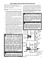
Gas line hook up should be done by your
supplier or a qualied service person.
Note: Before you proceed, make sure your
gas supply is turned off.
Use only a 1/2" black iron pipe and appropri-
ate ttings.
1. Remove knockout indentation on refrac-
tory or rebrick wall located above refrac-
tory hearth oor. Knockout indentation
must be rmly tapped with any solid object
such as a 1/2" dowel until it is released.
Remove fragmented portions of refractory
(see Figure 21).
2. Remove gas line cover plate located on
either side of replace and pull out insula-
tion from gas line conduit sleeve. Save
insulation for reuse. Replace screws.
3. Run a 1/2" black iron gas line into replace
through the rear at gas line conduit sleeve (if
using a raised platform, add height). Provide
sufcient gas line into replace chamber for
tting connection (see Figure 22).
Note: Secure incoming gas line to wood
framing to provide rigidity for threaded end.
4. Repack insulation around gas line and into
sleeve opening. Seal any gaps between
gas line and refractory knockout hole with
refractory cement or commercial furnace
cement, Install the gas appliance or cap-off
gas line if desired.
and connections must be tested
for leaks after the installation
is completed. After ensuring
that the gas valve is on, apply
soap and water solution to all
forming show a leak. Correct
-
-
-
place with the chimney removed.
Figure 21 - Gas Line Access
Side
Firebrick
Finished
Side
Brick with
Access
Hole
Outside of
Fireplace
Gas Line
Conduit
Insulation
Gas
Conduit
Cover
1/2" Dowel
Seal
Opening
with
Refractory
Cement
Outside of
Fireplace
Gas Line
Conduit
Repack
Insulation
Incoming
1/2" Black
Iron Pipe
Side
Firebrick
Finished
Side
Provide Enough
Threaded
End for Fitting
Connection
Figure 22 - Gas Line Installation
Remove
Knockout
OPTIONAL GAS LINE INSTALLATION
If you install a decorative gas appliance
(vented gas log), the decorative gas appliance
must comply with the Standard for Decorative
Gas Appliance for Installation in Solid Fuel
Burning Fireplaces, ANS Z21.60, Z21.84 or
RG 2-72 and shall also be installed in accor-
dance with the National Fuel Gas Code, ANSI
7223NFPA 54 latest edition.
has been used for wood burning,
cleaned of soot, creosote and
cleaner. Creosote will ignite if
heavily heated.
decorative vented gas log, the
damper must be removed or per-
manently locked in the fully open
position and the glass doors must
be in the fully open position.

www.desatech.com
122271-01B14
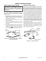
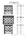
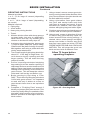
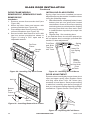
Figure 24 - Installing Brick
Brick
Stamped
Letter
Location
Brick Housing
Flanges
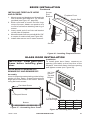
BRICK INSTALLATION
-
place is placed in a permanent
location.
The brick housings are already installed on
the panels. When installing brick housing
panels into replace, wear gloves as edges
may be sharp.
1. Beginning with left side panel, place
panel, bottom edge rst, at an angle into
replace. Secure to bottom of replace
with screws provided.
2. Install right side as left side in step 1 using
screws provided.
3. Install back panel and secure back to
sides and bottom of rebox with screws
provided.
4. Using self-tapping screws and a drill, place
screws into large holes in back and side
panels (see Parts, page 34), through wire
mesh and into rebox wrapper to secure.
Figure 23 - Hole in Side Panel to Attach
to Firebox Wrapper
Hole in
Side Panel
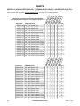
Each brick housing is stamped with a number
(full size bricks are not stamped). These num-
bers will help identify the brick when installing.
It is important to install these bricks exactly as
instructed. Press brick rmly into brick housing
until it snaps. Groove line on side of brick will
come in contact with ange on the brick hous-
ing. This secures brick into housing (see Figure
24). Smaller bricks may require a small portion
of furnace cement applied to back of brick to
secure it until grouting has been completed.
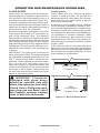
Bricks are packaged in separate boxes. The
brick matrixes on pages 15 through 27 show
how bricks are packaged and placed for each
size replace and the number of bricks per
box. There are 2 extra full bricks included in
Hearth Brick package.
Install bricks one section at a time starting with
hearth panel followed by the rear panel, left
panel and right panel. It is important to install
the bricks in sequence. Please note, full size
bricks are NOT stamped.

www.desatech.com
122271-01B 15
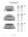
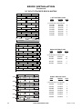
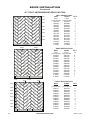
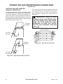
BRICK INSTALLATION
Continued
50" Hearth
FULL FULL
FULL FULL
FULL FULL
FULL
FULL FULL
FULL
F011 F011
FULL FULL
FULL
120848
FULL
F011
FULL
F059F134
F025
F134F012 F012 F059
F126 F126
F021F021
F135
F135
F025
F024F024
Ash Brick
FULL
F124
F125 F125
F128 F128F012 F012
F126 F126
120848
Ash Brick
FULL
FULL
FULL
FULL
FULL
FULL FULL FULL
F124
FULL FULL
FULL FULL FULL
FULL FULL
FULL FULL
FULL
120848
FULL
F132 F132
F059 F059 F059 F059
F133
F123
F124
F126 F126
F124
F123
F133F011
Ash Brick
42" Hearth
36" Hearth
FULL
(112140-01)
FULL
(112140-05)
13*
ASH BRICK
(120848-01)
ASH BRICK
(120848-03)
1
F011R F011W 1
F059R F059W 4
F123R F123W 2
F124R F124W 2
F126R F126W 2
F132R F132W 2
F133R F133W 2
* Includes 2 extra bricks.
FULL
(112140-01)
FULL
(112140-05)
11*
ASH BRICK
(120848-01)
ASH BRICK
(120848-03)
1
F012R F012W 2
F124R F124W 2
F125R F125W 2
F126R F126W 2
F128R F128W 2
* Includes 2 extra bricks.
FULL
(112140-01)
FULL
(112140-05)
17*
ASH BRICK
(120848-01)
ASH BRICK
(120848-03)
1
F011R F011W 3
F012R F012W 2
F021R F021W 2
F024R F024W 2
F025R F025W 2
F059R F059W 2
F126R F126W 2
F134R F134W 2
F135R F135W 2
* Includes 2 extra bricks.

www.desatech.com
122271-01B16
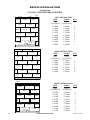
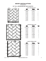
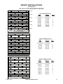
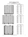
BRICK INSTALLATION
Continued
FULL
(112140-01)
FULL
(112140-05)
8
F148R F148W 1
F150R F150W 2
F152R F152W 1
F153R F153W 2
F159R F159W 6
F160R F160W 4
FULL
(112140-01)
FULL
(112140-05)
7
F036R F036W 3
F143R F143W 2
F144R F144W 1
F147R F147W 1
F148R F148W 2
F158R F158W 3
F185R F185W 1
F191R F191W 1
F192R F192W 1
FULL
(112140-01)
FULL
(112140-05)
7
F036R F036W 3
F143R F143W 2
F144R F144W 1
F147R F147W 1
F148R F148W 2
F158R F158W 3
F185R F185W 1
F191R F195W 1
F192R F192W 1
F148F148
FULL
FULLFULL
FULL
FULL
F036
F036
F036F158
F143F143
F144
F158
F158
F192
FULLFULL
F148F148
FULL
FULLFULL
FULL
FULL
F036
F036
F036 F158
F143F143
F144
F158
F158
F185 or
F191
F185 or
F191
F192
FULLFULL
F147
F147
F153F152
FULLFULL
FULL
FULL
FULLFULL
FULLFULL
F160
F160
F160
F160
F153
F148
F150F150
F159F159F159
F159F159F159
F148F148
FULL
FULLFULL
FULL
FULL
F036
F036
F036F158
F143F143
F144
F158
F158
F192
FULLFULL
F148F148
FULL
FULLFULL
FULL
FULL
F036
F036
F036 F158
F143F143
F144
F158
F158
F185 or
F191
F185 or
F191
F192
FULLFULL
F147
F147

www.desatech.com
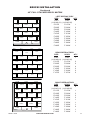
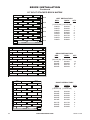
122271-01B 17
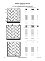
BRICK INSTALLATION
Continued
FULL
(112140-01)
FULL
(112140-05)
7
F017R F017W 2
F032R F032W 6
F033R F033W 4
F152R F152W 2
F154R F154W 2
F157R F157W 2
FULL
(112140-01)
FULL
(112140-05)
8
F017R F017W 1
F032R F032W 3
F033R F033W 3
F143R F143W 3
F151R F151W 1
F155R F155W 1
F156R F156W 1
F158R F158W 2
F186R F186W 1
F190R F190W 1
FULL
(112140-01)
FULL
(112140-05)
8
F017R F017W 1
F032R F032W 3
F033R F033W 3
F143R F143W 3
F151R F151W 1
F155R F155W 1
F156R F156W 1
F158R F158W 2
F186R F186W 1
F190R F190W 1
F155F017
FULLFULL
F032FULL
F033
F158
FULLFULL
F032FULL
F033
F158
FULLFULL
F143
F143
F143
F033
F151
F032
F156
F155 F017
FULLFULL
F032 FULL
F033
F158
FULLFULL
F032 FULL
F033
F158
FULLFULL
F143
F143
F143
F033
F151
F190 or F186 F190 or F186
F032
F156
F157
F033
F032FULL
F152F154 F154F152
FULLFULL
FULL
FULL
FULLFULL
F032
F032
F032
F032
F032
F033
F033
F033
F017F017F157
F155F017
FULLFULL
F032FULL
F033
F158
FULLFULL
F032FULL
F033
F158
FULLFULL
F143
F143
F143
F033
F151
F032
F156
F155 F017
FULLFULL
F032 FULL
F033
F158
FULLFULL
F032 FULL
F033
F158
FULLFULL
F143
F143
F143
F033
F151
F190 or F186 F190 or F186
F032
F156

www.desatech.com
122271-01B18
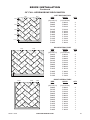
BRICK INSTALLATION
Continued
FULL
(112140-01)
FULL
(112140-05)
13
F148R F148W 2
F150R F150W 2
F152R F152W 2
F153R F153W 2
F159R F159W 6
F160R F160W 4
FULL
(112140-01)
FULL
(112140-05)
7
F032R F032W 3
F033R F033W 3
F143R F143W 2
F144R F144W 1
F145R F145W 1
F146R F146W 1
F147R F147W 1
F148R F148W 2
F149R F149W 1
F158R F158W 3
F191R F191W 1
F192R F191W 1
FULL
(112140-01)
FULL
(112140-05)
7
F032R F032W 3
F033R F033W 3
F143R F143W 2
F144R F144W 1
F145R F145W 1
F146R F146W 1
F147R F147W 1
F148R F148W 2
F149R F149W 1
F158R F158W 3
F191R F191W 1
F192R F192W 1
F148 F149F148
FULL
FULL
FULL
F032
F033
F158
F143
FULL
FULL
FULL
F032
F033
F033
F158
FULL
F032
F158
F143
F144
F147F147
F148
F149
F148
FULL
FULL
FULL
F032
F033
F158
F143
FULL
FULL
FULL
F032
F033
F033
F158
FULL
F032
F158
F143
F144
F145 or
F191
F145 or
F191
F146 or
F192
F146 or
F192
F150
FULL
F152F153 F153F152
FULLFULL
FULL
FULLFULL FULL
FULL FULL
FULL FULL
FULLFULL
F160
F160
F160
F160
F159
F159
F159
F159
F159
F159
F148F148F150
F148 F149F148
FULL
FULL
FULL
F032
F033
F158
F143
FULL
FULL
FULL
F032
F033
F033
F158
FULL
F032
F158
F143
F144
F147F147
F148
F149
F148
FULL
FULL
FULL
F032
F033
F158
F143
FULL
FULL
FULL
F032
F033
F033
F158
FULL
F032
F158
F143
F144
F145 or
F191
F145 or
F191
F146 or
F192
F146 or
F192

www.desatech.com
122271-01B 19
FULL
(112140-01)
FULL
(112140-05)
6
F068R F068W 1
F072R F072W 1
F074R F074W 6
F084R F084W 3
F107R F107W 3
F108R F108W 1
F117R F117W 1
F161R F161W 1
F168R F168W 2
F179R F179W 1
F187R F187W 1
FULL
(112140-01)
FULL
(112140-05)
6
F068R F068W 1
F071R F071W 1
F072R F072W 5
F074R F074W 2
F113R F113W 3
F115R F115W 1
F165R F165W 1
F181R F181W 1
F189R F189W 1
S011R S011W 1
FULL
(112140-01)
FULL
(112140-05)
3
F068R F068W 4
F071R F071W 1
F072R F072W 1
F074R F074W 2
F110R F110W 3
F112R F112W 1
F120R F120W 4
F122R F122W 4
F180R F180W 1
F181R F181W 1
F188R F188W 1
F120
F120
F120
F120
F072
F068
F068
F068
F068
FULL
FULL
FULL
F112
F110
F110
F110
F122
F180
F181 or F071
F188
F074
F074
F122
F122
F122
FULL
FULL
FULL
F068
FULL
F072
FULL
F161
FULL
F084
F084
F084
F179
F117
F187
F168
F168
F107
F107
F107
F108
F074
F074
F074
F074
F074
F074
F115
F068
F113
F113
F113
FULL
FULL
FULL
FULL
FULL
FULL
S011
F072
F072
F072
F072
F072
F165
F181 or F071
F189
F074 F074
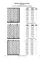
BRICK INSTALLATION
Continued

www.desatech.com
122271-01B20
FULL
(112140-01)
FULL
(112140-05)
9
F063R F063W 3
F068R F068W 1
F072R F072W 6
F074R F074W 2
F089R F089W 1
F161R F161W 2
F168R F168W 1
F171R F171W 1
F178R F178W 1
FULL
(112140-01)
FULL
(112140-05)
6
F064R F064W 4
F068R F068W 4
F072R F072W 2
F074R F074W 2
F120R F120W 4
F163R F163W 1
F169R F169W 1
F175R F175W 1
F176R F176W 1
F177R F177W 1
F182R F182W 1
FULL
(112140-01)
FULL
(112140-05)
9
F068R F068W 1
F071R F071W 4
F072R F072W 2
F074R F074W 1
F100R F100W 3
F101R F101W 1
F162R F162W 1
F164R F164W 1
F165R F165W 1
F174R F174W 1
FULL
F072
F163
F175 or F182
F169
F064
F064
F064
F064
F120
F068
F074 F074
F072
FULL
FULL
FULL
FULL
FULL
F068
F068
F068
F120
F120
F120
F176
F177
FULL
F063
F068
F072
F171
F072
F072
F072
F072
F072
F089
F161
F161
F168
F178
F063
F063
FULL
FULL
FULL
FULL
FULL
FULL
FULL
FULL
F074
F074
FULL
F072
F066
F066
F066
F066
F165
F164
F100
F100
F100
F101
F174
F068
F074
F162 or F184
F072
FULL
FULL
FULL
FULL
FULL
FULL
FULL
FULL
BRICK INSTALLATION
Continued
Page is loading ...
Page is loading ...
Page is loading ...
Page is loading ...
Page is loading ...
Page is loading ...
Page is loading ...
Page is loading ...
Page is loading ...
Page is loading ...
Page is loading ...
Page is loading ...
Page is loading ...
Page is loading ...
Page is loading ...
Page is loading ...
Page is loading ...
Page is loading ...
Page is loading ...
Page is loading ...
-
 1
1
-
 2
2
-
 3
3
-
 4
4
-
 5
5
-
 6
6
-
 7
7
-
 8
8
-
 9
9
-
 10
10
-
 11
11
-
 12
12
-
 13
13
-
 14
14
-
 15
15
-
 16
16
-
 17
17
-
 18
18
-
 19
19
-
 20
20
-
 21
21
-
 22
22
-
 23
23
-
 24
24
-
 25
25
-
 26
26
-
 27
27
-
 28
28
-
 29
29
-
 30
30
-
 31
31
-
 32
32
-
 33
33
-
 34
34
-
 35
35
-
 36
36
-
 37
37
-
 38
38
-
 39
39
-
 40
40


Ask a question and I''ll find the answer in the document
Finding information in a document is now easier with AI
Related papers
Other documents
-
FMI BDG42PB Operating instructions
-
-
-
 StarTech.com INSERTBLANK Datasheet
-
 StarTech.com PLATE2IV Datasheet
-
FMI C42L User guide
-
Astria Fireplaces citadel Operating instructions
-
-
-

