
For more information, visit www.fmiproducts.com
WARNING: If the information in this manual is not
— WHAT TO DO IF YOU SMELL GAS
-
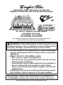
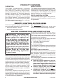
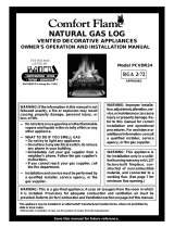
UNVENTED (VENT-FREE) GAS LOG HEATER
OWNER’S OPERATION AND INSTALLATION MANUAL
Not Used With Hand-Held Thermostat Remote
24" AND 30" REMOTE CONTROL READY
BILTMORE SPLIT OAK
CCL3924NRA, CCL3924PRA
CCL3930NRA, CCL3930PRA
P
I
L
O
T
O
F
F
O
N
LO
REMOTE
OFF
HI
PFS
®
US

www.fmiproducts.com
111161-01L2
SAFETY
alteration, service or
maintenance can cause
-
for correct installation
-
additional information
-
-
masonry or UL127 factory-
-
for these installations in
accordance with ANSI
that includes instructions
-
WARNING: This is an
-
from the room in which
and ventilation air must
Air
for Combustion and Ven-
tilation
-
stalled in an aftermarket,*
-
TABLE OF CONTENTS
Safety .................................................................. 2
Local Codes......................................................... 5
Product Identication ........................................... 5
Unpacking............................................................ 5
Product Features ................................................. 6
Remote Control Accessories ............................... 6
Air For Combustion and Ventilation ..................... 6
Installation ........................................................... 9
Operation ........................................................... 19
Inspecting Burners............................................. 21
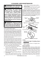
Cleaning and Maintenance ................................ 22
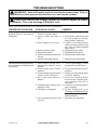
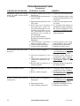
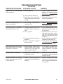
Troubleshooting ................................................. 23
Specications .................................................... 27
Wiring Diagram .................................................. 27
Parts .................................................................. 28
Replacement Parts ............................................ 30
Technical Service............................................... 30
Service Hints ..................................................... 30
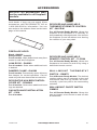
Accessories ....................................................... 31
Warranty ..............................................Back Cover

www.fmiproducts.com
111161-01L 3
chemicals known to the state
of California to cause cancer or
-
-
-
Early signs
of carbon monoxide poisoning resemble the
u, with headaches, dizziness or nausea. If
you have these signs, the heater may not
be working properly.
Have heater serviced. Some people are
more affected by carbon monoxide than oth-
ers. These include pregnant women, people
with heart or lung disease or anemia, those
under the inuence of alcohol and those at
high altitudes.
Natural and
propane/LP gases are odorless. An odor-
making agent is added to the gas. The odor
helps you detect a gas leak. However, the
odor added to the gas can fade. Gas may be
present even though no odor exists.
Make certain you read and understand all
warnings. Keep this manual for reference. It
is your guide to safe and proper operation of
this heater.
this heater or its controls can
SAFETY
Continued
WARNING: Do not use a
-
WARNING: Do not allow fans
will remain hot for a time after
-
dren when they are in the room
-
-
-

www.fmiproducts.com
111161-01L4
SAFETY
Continued
1. This appliance is only for use with the type
of gas indicated on the rating plate. This
appliance is not convertible for use with
other gases.
2. Do not place propane/LP supply tank(s)
inside any structure. Locate propane/LP
supply tank(s) outdoors (propane/LP units
only).
3. To prevent performance problems, the
use of a propane/LP fuel tank of less
than 100 lb. capacity is not recommended
(propane/LP units only).
4. If you smell gas
• shut off gas supply
• do not try to light any appliance
• do not touch any electrical switch; do not
use any phone in your building
• immediately call your gas supplier from
a neighbor’s phone. Follow the gas sup-
plier’s instructions
• if you cannot reach your gas supplier,
call the re department
5. This heater shall not be installed in a
bedroom or bathroom unless installed as
a vented appliance (see Installing Damper
Clamp Accessory for Vented Operation,
page 12).
6. Before installing in a solid fuel burning re-
place, the chimney ue and rebox must
be cleaned of soot, creosote, ashes and
loose paint by a qualied chimney cleaner.
Creosote will ignite if highly heated. A dirty
chimney ue may create and distribute
soot within the house. Inspect chimney
ue for damage. If damaged, repair ue
and rebox before operating heater.
7. Do not burn solid-fuel in a masonry or
UL127 factory-built replace in which a
vent-free room heater is installed.
8. If replace has glass doors, never operate
this heater with glass doors closed. If you
operate heater with doors closed, heat
buildup inside replace will cause glass to
burst. Make sure there are no obstructions
across openings of replace.
9. This log heater is designed to be smoke-
less. If logs ever appear to smoke, turn off
heater and call a qualied service person.
Note: During initial operation, slight smok-
ing may occur due to log curing and heater
burning manufacturing residues.
10. To prevent the creation of soot, follow the
instructions in Cleaning and Maintenance,
page 22.
11. Before using furniture polish, wax, carpet
cleaner or similar products, turn heater off. If
heated, the vapors from these products may
create a white powder residue within burner
box or on adjacent walls or furniture.
12. This heater needs fresh, outside air ven-
tilation to run properly. This heater has an
Oxygen Depletion Sensing (ODS) safety
shutoff system. The ODS shuts down the
heater if not enough fresh air is available.
See Air for Combustion and Ventilation,
page 6. If heater keeps shutting off, see
Troubleshooting, page 23.
13. Do not run heater
• where ammable liquids or vapors are
used or stored
• under dusty conditions
14. Do not use this heater to cook food or burn
paper or other objects.
15. Do not use heater if any part has been ex-
posed to or under water. Immediately call
a qualied service technician to inspect
the room heater and to replace any part
of the control system and any gas control
which has been under water.
16. Do not operate heater if any log is broken.
Do not operate heater if a log is chipped
(dime-sized or larger).
17. Turn heater off and let cool before ser-
vicing, installing or repairing. Make sure
the remote selector switch is in the OFF
position. Only a qualied service person
should install, service or repair heater.
18. Make sure the remote selector switch is
in the OFF position when you are away
from home for long periods of time.
19. This heater must not be connected to any
external electrical source.
20. Operating heater above elevations of
4,500 feet may cause pilot outage.
21. Provide adequate clearances around air
openings.

www.fmiproducts.com
111161-01L 5
LOCAL CODES
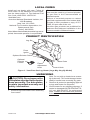
Figure 1 - Vent-Free Gas Log Heater (Logs May Vary By Model)
Log Set
Control Knob
Base Grate
Piezo
Ignitor
Optional
Remote
Control
Optional Selector Switch
Flame
Adjustment
Knob
UNPACKING
Install and use heater with care. Follow all
local codes. In the absence of local codes,
use the latest edition of The National Fuel
Gas Code, ANSI Z223.1/NFPA 54*.
*Available from:
American National Standards Institute, Inc.
1430 Broadway
New York, NY 10018
National Fire Protection Association, Inc.
Batterymarch Park
Quincy, MA 02269
Note: Where listed vented decorative logs are re-
quired, thermostat operation is not permitted.
State of Massachusetts: The installa-
tion must be made by a licensed plumber
or gas fitter in the Commonwealth of
Massachusetts.
Sellers of unvented propane or natural
gas-red supplemental room heaters shall
provide to each purchaser a copy of 527
CMR 30 upon sale of the unit.
Vent-free gas products are prohibited for
bedroom and bathroom installation in the
Commonwealth of Massachusetts.
PRODUCT IDENTIFICATION
CAUTION: Do not remove the
1. Remove logs and heater base assembly
from carton.
Note: Do not pick up heater base assem-
bly by burners. This could damage heater.
Always handle base assembly by grate.
2. Remove all protective packaging applied
to logs and heater for shipment.
3. Check heater for any shipping damage. If
heater is damaged call FMI PRODUCTS,
LLC at 1-866-328-4537 for replacement
parts. Please do not return this products
to the store.

www.fmiproducts.com
111161-01L6
PRODUCT FEATURES
This heater is clean burning. It requires
no outside venting. There is no heat loss
out a vent or up a chimney. Heat is gener-
ated by realistic dancing, yellow ames. This
heater is designed for vent-free operation
with ue damper closed. It has been tested
and approved to ANSI Z21.11.2 standard
for unvented heaters. This heater may also
be operated as a vented decorative (ANSI
Z21.60) product by opening flue damper
(non-thermostat models only).
This heater has a pilot with an Oxygen Deple-
tion Sensing (ODS) safety shutoff system. The
ODS/pilot is a required feature for vent-free
room heaters. The ODS/pilot shuts off the
heater if there is not enough fresh air.
This heater has a piezo ignitor. This system re-
quires no matches, batteries or other sources
to light heater.
REMOTE CONTROL ACCESSORIES
There are 2 optional remote controls that can
be purchased separately for this log heater:
• hand-held ON/OFF remote
• hand-held thermostat remote
See Accessories, page 31.
The hand-held thermostat may not be used
where vented decorative listing is required.
AIR FOR COMBUSTION AND VENTILATION
WARNING: This heater shall
-
-
National Fuel Gas
Code, ANSI Z223.1/NFPA 54, the
International Fuel Gas Code, or
Today’s homes are built more energy efcient
than ever. New materials, increased insulation and
new construction methods help reduce heat loss
in homes. Home owners weather strip and caulk
around windows and doors to keep the cold air out
and the warm air in. During heating months, home
owners want their homes as airtight as possible.
While it is good to make your home energy
efcient, your home needs to breathe. Fresh
air must enter your home. All fuel-burning ap-
pliances need fresh air for proper combustion
and ventilation.
Exhaust fans, replaces, clothes dryers and fuel
burning appliances draw air from the house to
operate. You must provide adequate fresh air for
these appliances. This will insure proper venting
of vented fuel-burning appliances.
The following are excerpts from National Fuel
Gas Code, ANSI Z223.1/NFPA 54, Air for
Combustion and Ventilation.
All spaces in homes fall into one of the three
following ventilation classications:
1. Unusually Tight Construction
2. Unconned Space
3. Conned Space
The information on pages 6 through 8 will help
you classify your space and provide adequate
ventilation.
The air that leaks around doors and windows
may provide enough fresh air for combustion
and ventilation. However, in buildings of un-
usually tight construction, you must provide
additional fresh air.
construction where:
-
-11
2
and
and

www.fmiproducts.com
111161-01L 7
AIR FOR COMBUSTION AND VENTILATION
Continued
If your home meets all of the three criteria
above, you must provide additional fresh air.
See Ventilation Air From Outdoors, page 8.
If your home does not meet all of the three
criteria above, proceed to Determining Fresh-
Air Flow For Heater Location.
The National Fuel Gas Code, ANSI Z223.1/
NFPA 54 denes a conned space as a space
whose volume is less than 50 cubic feet per
1,000 Btu/hr (4.8 m
3
per kw) of the aggregate
input rating of all appliances installed in that
space and an unconned space as a space
whose volume is not less than 50 cubic feet
per 1,000 Btu/hr (4.8 m
3
per kw) of the ag-
gregate input rating of all appliances installed
in that space. Rooms communicating directly
with the space in which the appliances are
installed*, through openings not furnished
with doors, are considered a part of the un-
conned space.
* Adjoining rooms are communicating only if
there are doorless passageways or ventilation
grills between them.
DETERMINING FRESH-AIR FLOW
FOR HEATER LOCATION
Use this work sheet to determine if you have
a conned or unconned space.
Includes the room in which you will
install heater plus any adjoining rooms with
doorless passageways or ventilation grills
between the rooms.
1. Determine the volume of the space (length
x width x height).
Length x Width x Height =__________cu. ft.
(volume of space)
Example: Space size 20 ft. (length) x 16 ft.
(width) x 8 ft. (ceiling height) = 2560 cu. ft.
(volume of space)
If additional ventilation to adjoining room
is supplied with grills or openings, add the
volume of these rooms to the total volume
of the space.
2. Multiply the space volume by 20 to determine
the maximum Btu/Hr the space can support.
________ (volume of space) x 20 = (Maxi-
mum Btu/Hr the space can support)
Example: 2560 cu. ft. (volume of space) x 20
= 51,200 (maximum Btu/Hr the space can
support)
3. Add the Btu/Hr of all fuel burning appliances
in the space.
Vent-free replace __________ Btu/Hr
Gas water heater* __________ Btu/Hr
Gas furnace __________ Btu/Hr
Vented gas heater __________ Btu/Hr
Gas replace logs __________ Btu/Hr
Other gas appliances* + _________ Btu/Hr
Total = _________ Btu/Hr
* Do not include direct-vent gas appliances.
Direct-vent draws combustion air from the
outdoors and vents to the outdoors.
Example:
Gas water heater __________ Btu/Hr
Vent-free replace + _________ Btu/Hr
Total = _________ Btu/Hr
4. Compare the maximum Btu/Hr the space
can support with the actual amount of Btu/
Hr used.
_______ Btu/Hr (maximum the space can
support)
_______ Btu/Hr (actual amount of Btu/Hr
used)
Example: 51,200 Btu/Hr (maximum the
space can support)
79,000 Btu/Hr (actual amount of
Btu/Hr used)
The space in the above example is a conned
space because the actual Btu/Hr used is more
than the maximum Btu/Hr the space can sup-
port. You must provide additional fresh air. Your
options are as follows:
A. Rework worksheet, adding the space of an
adjoining room. If the extra space provides
an unconned space, remove door to adjoin-
ing room or add ventilation grills between
rooms. See Ventilation Air From Inside
Building, page 8.
B. Vent room directly to the outdoors. See
Ventilation Air From Outdoors, page 8.
C. Install a lower Btu/Hr replace, if lower Btu/
Hr size makes room unconned.
If the actual Btu/Hr used is less than the maxi-
mum Btu/Hr the space can support, the space is
an unconned space. You will need no additional
fresh air ventilation.
40,000
39,000
79,000

www.fmiproducts.com
111161-01L8
WARNING: If the area in which
-
National Fuel
Gas Code, ANSI Z223.1/NFPA 54,
the International Fuel Gas Code,
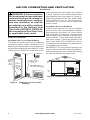
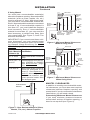
This fresh air would come from an adjoining
unconned space. When ventilating to an
adjoining unconned space, you must provide
two permanent openings: one within 12" of the
ceiling and one within 12" of the oor on the
AIR FOR COMBUSTION AND VENTILATION
Continued
wall connecting the two spaces (see options
1 and 2, Figure 2). You can also remove door
into adjoining room (see option 3, Figure 2).
Follow the National Fuel Gas Code, ANSI
Z223.1/NFPA 54, Air for Combustion and
Ventilation for required size of ventilation
grills or ducts.
Provide extra fresh air by using ventilation
grills or ducts. You must provide two perma-
nent openings: one within 12" of the ceiling
and one within 12" of the oor. Connect these
items directly to the outdoors or spaces open
to the outdoors. These spaces include attics
and crawl spaces. Follow the National Fuel
Gas Code, ANSI Z223.1/NFPA 54, Air for
Combustion and Ventilation for required size
of ventilation grills or ducts.
IMPORTANT: Do not provide openings for
inlet or outlet air into attic if attic has a thermo-
stat-controlled power vent. Heated air entering
the attic will activate the power vent.
Figure 3 - Ventilation Air from Outdoors
Figure 2 - Ventilation Air from Inside
Building
Outlet
Air
V e ntilated
Attic
Outlet
A
ir
Inlet
Air
Inlet Air
V e ntilated
Crawl Space
T o
Crawl
Space
T o Attic
Or
Remove
Door into
Adjoining
Room,
Option
3
Ve ntilation Grills
Into Adjoining Room,
Option 2
Ve ntilation
Grills Into
Adjoining
Room,
Option 1
12"
12"

www.fmiproducts.com
111161-01L 9
WARNING: Seal any fresh
air vents or ash clean-out doors
-
WARNING: Never install the
heater
unless installed as a vented
CAUTION: This heater cre-
currents move heat to wall sur-
heater next to vinyl or cloth wall
-
the air exist, may discolor walls
IMPORTANT: Vent-free heaters add moisture
to the air. Although this is benecial, installing
heater in rooms without enough ventilation
air may cause mildew to form from too much
moisture. See Air for Combustion and Ventila-
tion, page 6.
INSTALLATION
NOTICE: This heater is intended
-
NOTICE: State or local codes
-
-
WARNING: Make sure the
-
-
-

www.fmiproducts.com
111161-01L10
Use the correct gas type (natural or propane/
LP) for your unit. If your gas supply is not cor-
rect, do not install heater. Call dealer where
you bought heater for proper type heater.
-
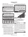
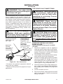
INSTALLATION AND CLEARANCES
WARNING: Maintain the
Side Wall 16" Ceiling: 42"
24" 17" 13" 28" 21"
30" 17" 13" 34" 24"
* Measured at 13" depth.
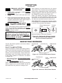
Carefully follow the instructions below. This
will ensure safe installation into a masonry,
UL127-listed manufactured replace or listed
vent-free rebox.
-
A. Clearances from the side of the replace
cabinet to any combustible material and
wall should follow diagram in Figure 4.
Example: The face of a mantel, bookshelf,
etc. is made of combustible material and
protrudes 3
1
/
2
" from the wall. This com-
bustible material must be 4" from the side
of the replace opening (see Figure 4).
Note: When installing your gas logs into
a manufactured rebox, follow rebox
manufacturer’s instructions for minimum
clearances to combustible materials.
INSTALLATION
Continued
Figure 4 - Minimum Clearance for
Combustible to Wall
*Minimum 16" from Side Wall
*
Example
Clearances
Note: If using a mantel, proceed to If Using
Mantel, page 11. If not using a mantel, follow
the information below.
You must have noncombustible material(s)
above the replace opening. Noncombustible
materials (such as slate, marble, tile, etc.)
must be at least 1/2" thick. With sheet metal,
you must have noncombustible material be-
hind it. Noncombustible material must extend
at least 8" up. If noncombustible material is
less than 12", you must install the replace
hood accessory. See Figure 5, page 11, for
minimum clearances.
IMPORTANT: If you cannot meet these mini-
mum clearances, you must operate heater
with chimney ue damper open. Go to Install-
ing Damper Clamp Accessory for Vented
Operation, page 12.
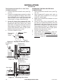
B. Clearances from top of replace opening
to ceiling should not be less than 42".
NOTICE: Manual control heaters
If so, you must always run heater
Installing Damper
Clamp Accessory for Vented
Operation

www.fmiproducts.com
111161-01L 11
INSTALLATION
Continued
Figure 5 - Heat Resistant Material (Slate,
Marble, Tile, etc.) Above Fireplace
You must have noncombustible material(s)
above the replace opening. Noncombustible
materials (such as slate, marble, tile, etc.)
must be at least 1/2" thick. With sheet metal,
you must have noncombustible material be-
hind it. Noncombustible material must extend
at least 8" up. If noncombustible material is
less than 12", you must install the replace
hood accessory. Even if noncombustible
material is more than 12", you may need the
hood accessory to deect heat away from
your mantel shelf. See Figure 5, 6 and 7 for
minimum clearances.
IMPORTANT: If you cannot meet these mini-
mum clearances, you must operate heater
with chimney ue damper open. Go to Install-
ing Damper Clamp Accessory for Vented
Operation, page 12.
-
Installation
12" or more Noncombustible material
okay.
B e t w e e n 8 "
and 12"
Install replace hood acces-
sory (GA6050 or GA6053
see Accessories, page
31).
Less than 8" Noncombustible material
must be extended to at
least 8". See Between 8"
and 12", above. If you can-
not extend material, you
must operate heater with
ue damper open.
Heat Resistant
Material
(A)
MANTEL CLEARANCES
In addition to meeting noncombustible mate-
rial clearances, you must also meet required
clearances between replace opening and
mantel shelf. If you do not meet the clearances
listed below, you will need a hood.
If you meet minimum clearance between
mantel shelf and top of replace opening, a
hood is not required (see Figure 6).
Figure 6 - Minimum Mantel Clearances
Without Using Hood
Minimum
Noncombustible
Material
Minimum
Noncombustible
Material Height
Distances to
Underside of
Mantel
Top of
Fireplace
Opening
Underside
of Mantel
Shelf
Mantel Shelf
12"
(A)
18" 20" 22" 24"
All minimum
distances are
in inches
Log Set
All
Models
2
1
/2
"
6"
8"
10"
Minimum
Noncombustible
Material
8"
Min.
12" 15" 18"
All minimum
distances are
in inches
Log Set
18", 24",
30" Models
20"
2
1
/2
"
6"
8"
10"
12"
Distances to
Underside of
Mantel
Hood
(GA6050,
GA6052)
T o p of
Fireplace
Opening
Underside
of Mantel
Shelf
Mantel Shelf
Figure 7 - Minimum Mantel Clearances
When Using Hood
All
Models

www.fmiproducts.com
111161-01L12
INSTALLATION
Continued
If minimum clearances in Figure 6, page 11,
are not met, you must have a hood. When
using a hood there are still certain minimum
mantel clearances required. Follow minimum
clearances shown in Figure 7, page 11, when
using hood.
-
-
Follow all minimum clearances
NOTICE: If your installation does
not meet the minimum clear-
ances shown, you must do one
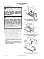
FLOOR CLEARANCES
A. If installing appliance on the oor level,
you must maintain the minimum distance
of 14" to combustibles (see Figure 8).
B. If combustible materials are less than 14"
to the replace, you must install appliance
at least 5" above the combustible ooring
(see Figure 9).
14"
Min.
Combustible
Material
Noncombustible Material
Hearth
5"
Min.
Combustible
Material
Figure 9 - Minimum Fireplace Clearances
Above Combustible Flooring
Figure 8 - Minimum Fireplace Clearances
If Installed at Floor Level
-
Note: When used as a vented heater, ap-
pliance must be installed only in a solid-fuel
burning replace with a working ue and con-
structed of noncombustible material.
If you choose to use your heater as a man-
ually-controlled model (no remote control
installed), you may use this heater as a vented
product. There are three reasons for operating
your heater in the vented mode.
1. Fireplace does not meet the clearance to
combustibles requirements for vent-free
operation.
2. State or local codes do not permit vent-
free operation.
3. You prefer vented operation.
If reasons number 1 or 2 above apply to you,
you must permanently open chimney ue
damper. You must install the damper clamp
accessory (to order, see Accessories, page
31). This will insure vented operation (see
Figure 10, page 13). The damper clamp will
keep damper open. Installation instructions
are included with clamp accessory.
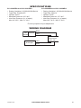
See chart below for minimum permanent ue
opening you must provide. Attach damper
clamp so the minimum permanent ue open-
ing will be maintained at all times.
6' to 15' 39 sq. inches
15' to 30' 29 sq. inches
Diameter Area
5"
6"
7"
8"
20 sq. inches
29 sq. inches
39 sq. inches
51 sq. inches

www.fmiproducts.com
111161-01L 13
CAUTION: Do not remove the
WARNING: You must secure
not, heater will move when you
-
-
IMPORTANT: Make sure heater burners are level.
If heater is not level, heater will not work properly.
Figure 10 - Attaching Damper Clamp
Damper
Damper
Clamp
Damper
Damper
Clamp
Damper
INSTALLATION
Continued
Installation Items Needed
• hardware package (provided with heater)
• approved exible gas hose (not provided)
(if allowed by local codes)
• sealant resistant to propane/LP gas, not
provided
• electric drill with 3/16" masonry drill bit
Note: Install optional remote receiver and
hand-held remote kit (see Accessories, page
31) before installing gas log heater. See instal-
lation instructions included with the kit.
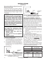
1. Apply pipe joint sealant lightly to male
threads of the tting to be threaded into
gas regulator. Connect approved exible
gas hose to gas regulator of heater (see
Figure 11).
2. Locate masonry screws in hardware
package.
3.
Position heater base assembly in replace.
4. Place logs in their proper positions on
heater base.
5. Center heater base and logs front to back
and side to side in replace.
6. Carefully remove logs without moving
heater base.
7. Mark screw locations through holes in
mounting anges (see Figure 12). If in-
stalling in a brick-bottom replace, mark
screw locations in mortar joint of bricks.
8. Remove heater base from replace.
9. Drill holes at marked locations using 3/16"
masonry drill bit.
Figure 11 - Attaching Flexible Gas Hose
to Heater
Flexible Gas Hose
(if allowed by local codes)
Fitting
Figure 12 - Attaching Base Assembly to
Fireplace Floor
Masonry
Screw
Mounting
Flanges

www.fmiproducts.com
111161-01L14
For propane/LP units, the installer must
supply an external regulator. The external
regulator will reduce incoming gas pressure.
You must reduce incoming gas pressure to
between 11" and 14" of water. If you do not re-
duce incoming gas pressure, heater regulator
damage could occur. Install external regulator
with the vent pointing down as shown in Figure
13. Pointing the vent down protects it from
freezing rain or sleet.
CAUTION: Use only new,
-
Installation must include an equipment shutoff
valve, union and plugged 1/8" NPT tap. Locate
NPT tap within reach for test gauge hook up.
NPT tap must be upstream from heater (see
Figure 14, page 15).
IMPORTANT: Install equipment shutoff valve
in an accessible location. The equipment
shutoff valve is for turning on or shutting off
the gas to the appliance.
Check your building codes for any special
requirements for locating equipment shutoff
valve to replaces.
Apply pipe joint sealant lightly to male NPT
threads. This will prevent excess sealant from
going into pipe. Excess sealant in pipe could
result in clogged heater valves.
INSTALLATION
Continued
Figure 13 - External Regulator With Vent
Pointing Down
Propane/LP
Supply Tank
External
Regulator
with Vent
Pointing
Down
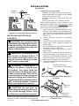
10. Attach base assembly to replace oor
using two masonry screws (in hardware
package) (see Figure 12, page 13).
11. Connect to gas supply. See Connecting
To Gas Supply.
-
CAUTION: Never connect
-
WARNING: Never connect
Installation Items Needed
Before installing heater, make sure you have
the items listed below.
• piping (check local codes)
• sealant (resistant to propane/LP gas)
• equipment shutoff valve *
• test gauge connection *
• sediment trap
• tee joint
• pipe wrench
* equipment shutoff valve with 1/8" NPT tap
is an acceptable alternative to test gauge
connection. Purchase the optional CSA
design-certied equipment shutoff valve from
your dealer.

www.fmiproducts.com
111161-01L 15
INSTALLATION
Continued
* Purchase the optional equipment shutoff
valve from your dealer.
** Minimum inlet pressure for purpose of input
adjustment.
Figure 14 - Gas Connection
Gas Control
3" Minimum
Equipment Shutoff
Valve With 1/8"
NPT Tap*
Approved
Flexible
Gas Hose (if
allowed by
local codes)
From External
Regulator (11"
W.C.** to 14" W.C.
Pressure)
NATURAL
From Gas Meter
(5" W.C.** to
10.5" W.C.
Pressure)
Cap Pipe Tee
Nipple Joint
Sediment Trap
We recommend that you install a sediment
trap in supply line as shown in Figure 14.
Locate sediment trap where it is within reach
for cleaning. Install in piping system between
fuel supply and heater. Locate sediment
trap where trapped matter is not likely to
freeze. A sediment trap traps moisture and
contaminants. This keeps them from going
into heater controls. If sediment trap is not
installed or is installed wrong, heater may
not run properly.
CHECKING GAS CONNECTIONS
and connections, internal and
external to unit, for leaks after
WARNING: Never use an
-
leaks at once
CAUTION: Make sure exter-
-
der Connecting to Gas Supply,
1. Disconnect appliance with its appliance
main gas valve (control valve) and equip-
ment shutoff valve from gas supply piping
system. Pressures in excess of 1/2 psig
will damage heater regulator.
2. Cap off open end of gas pipe where equip-
ment shutoff valve was connected.
3. Pressurize supply piping system by either
opening propane/LP supply tank valve
for propane/LP gas or opening main gas
valve located on or near gas meter for
natural gas or using compressed air.
4. Check all joints of gas supply piping sys-
tem. Apply noncorrosive leak detection
uid to gas joints. Bubbles forming show
a leak.
5. Correct all leaks at once.
6. Reconnect heater and equipment shutoff
valve to gas supply. Check reconnected
ttings for leaks.

www.fmiproducts.com
111161-01L16
INSTALLATION
Continued
1. Close equipment shutoff valve (see Fig-
ure 15).
2. Pressurize supply piping system by either
opening propane/LP supply tank valve
for propane/LP gas or opening main gas
valve located on or near gas meter for
natural gas or using compressed air.
3. Check all joints from propane/LP sup-
ply tank to equipment shutoff valve for
propane/LP gas (see Figure 16) or from
gas meter to equipment shutoff valve for
natural gas (see Figure 17). Apply noncor-
rosive leak detection uid to gas joints.
Bubbles forming show a leak.
4. Correct all leaks at once.
Figure 15 - Equipment Shutoff Valve
Open
Closed
Equipment
Shutoff
Valve
Figure 16 - Checking Gas Joints
Propane/LP
Tank
Equipment
Shutoff Valve
Control Valve Location
Figure 17 - Checking Gas Joints
Gas Meter
Equipment
Shutoff Valve
Control Valve Location
CONNECTIONS
1. Open equipment shutoff valve (see Fig-
ure 15).
2. Open propane/LP supply tank valve or
main gas valve located on or near gas
meter for natural gas.
3. Make sure control knob of heater is in the
OFF position.
4. Check all joints from propane/LP sup-
ply tank to equipment shutoff valve for
propane/LP gas (see Figure 16) or from
gas meter to equipment shutoff valve for
natural gas (see Figure 17). Apply noncor-
rosive leak detection uid to gas joints.
Bubbles forming show a leak.
5. Correct all leaks at once.
6. Light heater (see Operation, page 19).
Check all other internal joints for leaks.
7. Turn off heater (see To Turn Off Gas to
Appliance, page 20).

www.fmiproducts.com
111161-01L 17
INSTALLATION
Continued
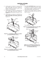
INSTALLING LOGS
-
CAUTION: After installa-
With the heater set to Hi, check
-
Each log is marked with a number. These
numbers will help you identify the log when
installing. It is very important to install these
logs exactly as instructed. Do not modify logs.
Only use logs supplied with heater.
1. Place front log (#1) on grate ngers. Make
sure front log rests rmly between grate
ngers and grate base (see Figure 18).
2. Place base of middle log (#2) in the U-
shaped slots of grate base. The cutout on
the right of middle log should t over the
burner (see Figure 19). Make sure front
of middle log is resting on tabs of grate
base.
3. Locate pegs on bottom of back log (#3).
Slide pegs into holes in grate base behind
burner (see Figure 20).
A
UT
O
OFF
ON
Figure 18 - Installing Front Log (#1)
(CCL3930PR/NRA Shown)
Front Log
(#1)
Grate
Fingers
Grate
Base
AU
T
O
OFF
ON
Figure 219- Installing Middle Log (#2)
(CCL3930PR/NRA Shown)
Middle Log (#2)
Tab
Burner
U-Shaped
Slot
AUTO
OFF
ON
Figure 20 - Installing Rear Log (#3)
(CCL3930PR/NRA Shown)
Hole in
Grate
Base
Pegs
Burner

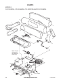
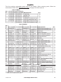
www.fmiproducts.com
111161-01L18
4. Locate pegs on bottom of crossover log
(#4). Slide pegs into holes located in
middle log (#2) and back log (#3). See
Figure 21, for placement.
5. Locate pegs on bottom of crossover log
(#5). Slide pegs into holes located in
crossover log (#4) and front log (#1). See
Figure 22.
6. Locate pegs on bottom of crossover log
(#6). Slide pegs into holes located in
middle log (#2) and front log (#1). See
Figure 23.
INSTALLATION
Continued
A
U
TO
OFF
ON
Figure 21 - Installing Crossover Log (#4)
(CCL3930PR/NRA Shown)
Log #2
Log #3
Pegs
Figure 22 - Installing Crossover Log (#5)
(CCL3930PR/NRA Shown)
A
U
TO
OFF
ON
7
Figure 24 - Installing Crossover Log
(#7) to Models CCL3930PR/PRA and
CCL3930NR/NRA Only
Middle Log
(#2)
Crossover
Log (#6)
Holes
Pegs
Figure 23- Installing Crossover Log (#6)
(CCL3930PR/NRA Shown)
AU
TO
OFF
ON
Crossover
Log (#4)
Front Log (#1)
AUTO
OFF
ON
6
Pegs
Log #2
Front Log (#1)
7. Locate holes
on bottom of crossover log (#7). Slide
onto pegs located in crossover log (#6)
and middle log (#2). See Figure 24.
8. Add lava rock around base of heater if
desired. Do not place any lava rock on
logs or burner.

www.fmiproducts.com
111161-01L 19
OPERATION
LIGHTING
INSTRUCTIONS
WARNING:
-
erate heater with doors closed,
-
-
Note: Home owners generally prefer to oper-
ate their heater with the chimney damper
closed. This will put all the heat into the room.
However, there may be times you will desire
the full ames of the HI heat setting but will
nd the heat output excessive. You can open
the chimney damper (if you have one) fully or
partially to release some of the heat.
1. STOP! Read the safety information, col-
umn 1.
2. Make sure equipment shutoff valve is fully
open.
3. Set selector switch in the OFF position.
WARNING:
come on automatically within
one minute when the selector
FOR YOUR SAFETY
WARNING: If you do not fol-
low these instructions exactly,
-
WHAT TO DO IF YOU SMELL GAS
-

www.fmiproducts.com
111161-01L20
12. To leave pilot lit and shut off burners only:
turn control knob clockwise to the
PILOT position, or use remote control
manual OFF button, or set selector switch
in the OFF position.
CAUTION: Do not try to ad-
WARNING: Make sure the
selector switch is in the OFF
Heater will come on automati-
cally with selector switch in the
OPERATION
Continued
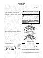
4. Press in and turn control knob clock-
wise to the OFF position (see
Figure 30).
5. Wait ve (5) minutes to clear out any gas.
Then smell for gas, including near the
oor. If you smell gas, STOP! Follow “B”
in the safety information, page 20. If you
don’t smell gas, go to the next step.
6. Press in and turn control knob counter-
clockwise to the PILOT position.
Press in control knob for ve (5) seconds
(see Figure 30).
Note: You may be running this heater for
the rst time after hooking up to gas sup-
ply. If so, the control knob may need to be
pressed in for 30 seconds or more. This will
allow air to bleed from the gas system.
7. With control knob pressed in, press and
release ignitor button. This will light pilot.
The pilot is attached to the front burner. If
needed, keep pressing ignitor button until
pilot lights.
Note: If pilot does not stay lit, contact a
qualied service person or gas supplier for
repairs. Until repairs are made, light pilot
with match. To light pilot with match, see
Manual Lighting Procedure, page 21.
8. Keep control knob pressed in for 30 sec-
onds after lighting pilot. After 30 seconds,
release control knob.
• If control knob does not pop out when
released, contact a qualified service
person or gas supplier for repairs.
Note: If pilot goes out, repeat steps 4
through 8.
9. Slightly push in and turn control knob coun-
terclockwise to the ON position.
10. Wait one minute and switch selector switch
to the ON position to light burners.
11. Set ame adjustment knob to any level
between HI and LO.
O
F
F
P
I
L
O
T
L
O
I
H
REMOTE
OFF
ON
O
N
Control
Knob
Ignitor
Button
Selector Switch
in OFF Position
Flame Adjustment
Knob
Figure 25 - Control Knob and Ignitor
Button Location
Figure 26 - Pilot
Ignitor
Electrode
Pilot Burner
Ignitor
Electrode
Pilot Burner
Natural Gas
TO TURN OFF GAS
1. Turn control knob clockwise to the
OFF position.
2a. Set selector switch in the OFF position.
2b.
Set selector switch in the OFF position to
keep from draining battery.
3. Close equipment shutoff valve (see Figure
15, page 16).
Page is loading ...
Page is loading ...
Page is loading ...
Page is loading ...
Page is loading ...
Page is loading ...
Page is loading ...
Page is loading ...
Page is loading ...
Page is loading ...
Page is loading ...
Page is loading ...
-
 1
1
-
 2
2
-
 3
3
-
 4
4
-
 5
5
-
 6
6
-
 7
7
-
 8
8
-
 9
9
-
 10
10
-
 11
11
-
 12
12
-
 13
13
-
 14
14
-
 15
15
-
 16
16
-
 17
17
-
 18
18
-
 19
19
-
 20
20
-
 21
21
-
 22
22
-
 23
23
-
 24
24
-
 25
25
-
 26
26
-
 27
27
-
 28
28
-
 29
29
-
 30
30
-
 31
31
-
 32
32


Desa CCL3930NRA Owner's manual
- Type
- Owner's manual
- This manual is also suitable for
Ask a question and I''ll find the answer in the document
Finding information in a document is now easier with AI
Related papers
-
Desa Tech VYD18P Owner's manual
-
Desa C User manual
-
Desa Tech CG2618PVA Owner's manual
-
Comfort Flame CCL3924NRA Owner's manual
-
Comfort Glow CG3324NTA Owner's manual
-
 Comfort Flame PCVDR24 Owner's manual
-
FMI CRL2718PA User manual
-
-
-
Desa Tech CGD3930N Owner's manual

Other documents
-
-
-
SHM VFM18LP Owner's Operation And Installation Manual
-
-
-
-
Real Fyre G18-2 See-Thru Owner's manual
-
-
Vermont Casting UC181N User manual
-