Page is loading ...

SAILOR SYSTEM 5000 MF/HF
150/250/500W
USER MANUAL


Introduction
Congratulations on your new SAILOR CU5100 MF/HF maritime radio telephone with built-in
DSC (Digital Selective Calling) system, fulfilling the highest international standards for
marine MF/HF communication and safety procedures. The transceiver is born with a
2187,5kHz DSC watch receiver forming an ideal system for MF GMDSS installations. The
transceiver can easily be upgraded for 6 channel scanning DSC watch receiver and Telex
operation to comply with MF/HF requirements in sea area A3. If connected to a GPS or other
maritime navigation system it can automatically include the true UTC time and your position
in its DSC distress messages.
This SAILOR marine equipment is a part of the modular system 5000 which also includes a
HF single sideband radiotelephone. SAILOR marine equipment is specially designed for the
extremely rugged conditions on bord a ship, based on more than 50 years’ experience with
all kinds of boats, from small pleasure crafts, over fishing boats working under all climatic
conditions, to the biggest ships.
SAILOR
®
is one of the worlds leading manufacturers of maritime radiocommunication
equipment - a position which has been maintained by means of constant and extensive
product development. We have a worldwide network of dealers with general agencies in
more than 80 countries. All our dealers are specially trained to service all your SAILOR ®
products.
About this manual
This manual is for the daily user of the system. Additionally, it includes a section on the
installation procedures, and - on page iii - standard distress procedures. We highly recom-
mend you to read the manual before you start using the equipment.
Notice: There may be some minor differences in the graphic layout of the manual compared
to the physical device.
Disclaimer
Any responsibility or liability for loss or damage in connection with the use of this product and
the accompanying documentation is disclaimed by Thrane & Thrane. The information in this
manual is provided for information purposes only, is subject to change without notice, may
contain errors or inaccuracies, and represents no commitment whatsoever by Thrane &
Thrane. This agreement is governed by the laws of Denmark.
Manuals issued by Thrane & Thrane are periodically revised and updated. Anyone relying on
this information should satisfy himself/herself as to the most current version. Providers with
access to Thrane & Thrane’s Extranet may obtain current copies of manuals at: http://
extranet.thrane.com.
Thrane & Thrane is not responsible for the content or accuracy of any translations or
reproductions, in whole or in part, of this manual from any other source.
i
0735

ii
0735
Training Information (valid for TU5160)
The System 5000 MF/HF is designed for “occupational use only” and is also classified as
such.
It must only be used in the course of employment by individuals aware of both the hazards
as well as the way to minimize those hazards.
The radio is thus NOT intended for use in an uncontrolled environment by general public.
The System 5000 MF/HF has been tested and complies with the FCC RF exposure limits for
“Occupational Use Only”. The radio also complies with the following guidelines and
standards regarding RF energy and electromagnetic energy levels including the
recommended levels for human exposure:
• FCC OET Bulletin 65 Supplement C, evaluating compliance with FCC guidelines for
human exposure to radio frequency electromagnetic fields
• American National Standards Institute (C95.1) IEEE standard for safety levels with
respect to human exposure to radio frequency electromagnetic fields, 3 kHz to 300
GHz
• American National Standards Institute (C95.3) IEEE recommended practice for the
measurement of potentially hazardous electromagnetic fields – RF and microwaves
Below the RF exposure hazards and instructions in safe operation of the radio within the
FCC RF exposure limits established for it are described.
Warning:
Your radio set generates electromagnetic RF (radio frequency) energywhen it is transmitting.
To ensure that you and those around you are not exposed to excessive amounts of that
energy (beyond FCC allowable limits for occupational use) and thus to avoid health hazards
from excessive exposure to RF energy, FCC OET bulletin 65 establishes an Maximum
Permissible Exposure (MPE) radius of 6" (1.8m) for the maximum power of your radio (150W
selected) with a whip antenna having a maximum gain of 3.0dBi.
This means all persons must be at least 6" (1.8m) away from the antenna when the radio is
transmitting.
Installation:
1. A whip antenna with a maximum power gain of 3 dBi must be mounted at least 12.6"
(3.9m) above the highest deck where people may be staying during radio transmissions.
The distance is to be measured vertically from the lowest point of the antenna. This
provides the minimum separation distance which is in compliance with RF exposure
requirements and is based on the MPE radius of 6" (1.8m) plus the 6.6" (2.0m) height of
an adult.
2 On vessels that cannot fulfil requirements in item 1, the antenna must be mounted so
that its lowest point is at least 6" (1.8m) vertically above the heads of people on deck and
all persons must be outside the 6" (1.8m) MPE radius during radio transmission.
• Always mount the antenna at least 6" (1.8m) from possible human access
• Never touch the antenna when transmitting
• Use only authorized T&T accessories
3. If antenna has to be placed in public areas or near people with no awareness of the radio
transmission, the antenna must be placed at a distance not less than 12" (3.6m) from
possible human access.
Failure to observe any of these warnings may cause you or other people to exceed FCC RF
exposure limits or create other dangerous conditions.

Abbreviations used in this manual
ADDR Address
AGC Automatic Gain Control
AM Amplitude Modulation
ARQ Automatic Repetition reQuest
CLRF Clarify
CU Control Unit
DIRTLX Direct Telex
DSC Digital Selective Calling
ETSI European Telecommunications Standards Institute
FEC Forward Error Correction
GA Go Ahead
GMDSS Global Maritime Distress and Safety System
GPS Global Positioning System
HF High Frequency
H3E Single sideband - full carrier
IMO International Maritime Organisation
IRS Information Receiving Station
ISS Information Sending Station
ITU International Telecommunication Union
J3E Single sideband - no carrier
MF Medium Frequency
MMSI Maritime Mobile Ship Identification
MOM Just a moment please
MSG Message
NBDP Narrow Band Direct Printing
PTT Push-To-Talk
RF-G Receiver Frequency Gain
Rx Receive
SSB Single Side Band
TEL Telephony
Tx Transmit
UTC Co-ordinated Universal Time
VHF Very High Frequency
WRU Who Are You
iii
0735

Safety instruction
DANGER
WARNING
Never touch the Antenna Tuning Unit or feeder wire when the
radiotelephone is transmitting.
High voltage which will cause death or serious injury is present at the
locations shown in the illustration below when the radiotelephone is
transmitting.
Unit
Tuning
Antenna
Feeder wire
(High Voltage)
99-126550
ELECTRICAL SHOCK HAZARD
Do not open the equipment.
Only qualified personnel should work inside the equipment.
iv
0735

Quick DSC distress call
(only for emergency use)
1. If necessary, switch on by pressing the ON/OFF button
2. Lift up the lid covering the orange key and press for 3 seconds.
3. The distress will be accompanied by a sound.
Distress message is sent at the continuous tone.
4. Wait for distress acknowledgement and start mayday procedure. Unless stopped
manually, by pressing the CANCEL softkey or switching the unit off, the distress call is
automatically repeated every 3½-4½ minutes until distress acknowledgement is received.
If an alarm panel is connected the MF/HF DISTRESS button on this unit will have the same
functionality as the distress button described above. All further handling should continue in
front of your main MF/HF DSC.
Mayday procedure
When DSC distress acknowledgement is received after you have pressed DISTRESS, or if
you otherwise need to commence distress traffic via radiotelephony on the distress traffic
frequency, follow this procedure:
• the distress signal MAYDAY, spoken three times;
• the words THIS IS;
• the NAME of the vessel in distress, spoken three times;
• the CALL SIGN or other identification;
• the MMSI if needed;
• the POSITION given as the LATITUDE and LONGITUDE or with respect to known
geographical location,
• the NATURE of the distress;
• the kind of ASSISTANCE required; and
• any other useful INFORMATION
Upon reception of a DSC distress alert from another ship in distress, you should acknowl-
edge the receipt by radiotelephony on the distress traffic frequency, by doing the following:
• the distress signal MAYDAY;
• the words THIS IS;
• the NAME of the vessel in distress, spoken three times;
• the NAME or other identification of own ship, spoken three times;
• “RECEIVED MAYDAY”.
Transmission of DSC distress alert on MF/HF (2, 4, 6, 8, 12, 16 MHz)
2187.5 kHz, 4207.5 kHz, 6312.0 kHz, 8414.5 kHz, 12577.0 kHz, 16804.5 kHz
0735
v

1 2345
678 910
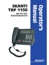
The MF/HF at a glance
(CU5100)
1. Display.
2. Dimming button.
3. Mode button used to.
toggle between modes.
4. Menu button.
Access to the menu system.
5. Keyboard.
6. Loudspeaker.
7. DISTRESS button.
Protected by shield. To use,
lift the shield and press for 3 seconds.
8. Soft keys.
The function of each key is described in
its respective field in the display above
each key.
9. Adjust/Tune.
Multi purpose rotary knob.
Controls backlight, frequency and RX
tune range.
10. ON/OFF / VOLUME control
vi
0735

1
0735
Contents
Introduction ............................................................................................................................. iii
About this manual ................................................................................................................iii
Training Information ............................................................................................................ iv
Abbreviations used in this manual ...................................................................................... v
Safety instruction ................................................................................................................ vi
Quick DSC distress call......................................................................................................... vii
Mayday procedure.................................................................................................................. vii
The MF/HF at a glance (CU5100) ......................................................................................... viii
1 MF/HF Fundamental info................................................................................................... 3
2 Basic functions .................................................................................................................. 4
2.1 Powering MF/HF ......................................................................................................... 4
2.2 Speaker volume .......................................................................................................... 4
2.3 Switches loudspeaker On/Off..................................................................................... 4
2.4 Change output power ................................................................................................. 4
2.5 Squelch On/Off ........................................................................................................... 4
2.6 Dimming ...................................................................................................................... 5
2.7 Change mode.............................................................................................................. 5
2.8 How to operate the menu ........................................................................................... 5
2.9 How to make a call to a coast station ........................................................................ 6
2.10 Telephony display functions ....................................................................................... 6
3 Voice call operation ........................................................................................................... 7
3.1 Operating MF/HF radio communication ..................................................................... 7
3.2 Listening for calls from a coast station....................................................................... 7
3.3 Enter Rx/Tx frequency................................................................................................ 8
3.4 Channel entry.............................................................................................................. 9
3.5 Select a channel from the station table.................................................................... 11
3.6 Re-tune the Antenna tuner ....................................................................................... 12
4 DSC operation .................................................................................................................. 13
4.1 DSC main.................................................................................................................. 13
4.2 DSC setup................................................................................................................. 14
4.3 Receiving a Distress Call ......................................................................................... 16
4.4 Receiving an Individual call ...................................................................................... 17
4.5 Sending a test call .................................................................................................... 19
4.6 Calling a coast station .............................................................................................. 21
4.7 Calling a ship ............................................................................................................ 23
4.8 Sending an area call ................................................................................................. 25
4.9 Repeat a call ............................................................................................................. 27
4.10 Composed DSC calls ............................................................................................... 28
4.11 DSC call menu .......................................................................................................... 30
4.12 Geographic Area Computation ................................................................................. 30
5 User setup......................................................................................................................... 31

2
0735
6 Telex operation................................................................................................................. 32
6.1 Telex setup................................................................................................................ 32
6.2 Simple telex operation .............................................................................................. 33
6.3
7 Data call ............................................................................................................................ 39
8 Scanning ........................................................................................................................... 40
9 Watch keeping receiver................................................................................................... 41
9.1 Watch receiver setup ................................................................................................ 41
10 Menu tree .......................................................................................................................... 42
11 Installation ........................................................................................................................ 44
11.1 Compass safe distance ............................................................................................ 44
Telex via data terminal ............................................................................................. 39

3
Basic
0725
1 MF/HF Fundamental info
Propagation of MF and HF Radio Waves.
MF/HF radiocommunications provide a medium and long range service. The 1.6-4 MHz
marine band is intended primarily for coastal operation beyond normal VHF communication
range. A reliable range of more than 150 nautical miles can be expected in most areas in the
daytime, more in the nighttime. Propagation of the radio waves in this band is mainly by
ground waves i.e. the waves from the transmitter aerial follow the earth’s curvature to the
receiver aerial. The high frequency range 4 - 30 MHz can provide communication for
hundreds or even thousands of nautical miles. The long range is achieved by sky waves
reflected from the ionosphere. Propagation of the radio waves depends on a number of
factors such as frequency, time of day, time of year, and solar activity. The channels
allocated to the maritime mobile service in the HF range are divided into a number of bands:
4, 6, 8, 12, 16, 18, 22, 25 MHz to allow a suitable frequency band to be selected for commu-
nication dependent on distance and time of day.
Radiotelephony
The mode of emission used for telephony transmissions in the marine bands is SSB (single-
sideband, J3E). On the international distress frequency 2182 kHz compatible AM (amplitude
modulation, H3E) may be used in addition for communication with non-GMDSS ships. AM
mode is used also when receiving broadcasting. The frequencies for radiotelephone distress
and safety traffic in the HF bands are 4125 kHz, 6215 kHz, 8291 kHz, 12290 kHz, and 16420
kHz. Working frequencies for public correspondence with coast stations are arranged in pairs
for duplex/semi-duplex operation. For the HF bands these channels are allocated numbers
by ITU on an international basis. In addition a number of simplex frequencies are available in
each band for ship-to-ship communication.
Radiotelex
Marine telex is also referred to as (NBDP) ‘Narrow Band Direct Printing’. Due to the narrow
bandwidth of the transmissions, a longer range may be expected compared to radiote-
lephony. The frequencies for radiotelex distress and safety traffic are 2174.5 kHz, 4177.5
kHz, 6268 kHz, 8376.5 kHz, 12520 kHz, and 16695 kHz. Working frequencies for public
correspondence with coast stations are arranged in pairs. For the HF bands these channels
are allocated numbers by ITU on an international basis. In addition a number of simplex
frequencies are available in each band for ship-to-ship communication.
DSC
DSC (Digital Selective Calling) is an automatic calling system which allows a specific station
to be contacted and made aware that a station wishes to communicate with it. In addition to
calls to specific stations the system can also be used to call groups of ships and this is of
significance for its use for DSC distress alerting. DSC is an alerting signal only and the
communication which follows the call is made on an appropriate frequency band using
radiotelephony or radiotelex. The frequencies for DSC distress and safety calling are 2187.5
kHz, 4207.5 kHz, 6312 kHz, 8414.5 kHz, 12577 kHz, and 16804.5 kHz. Calling frequencies
for public correspondence with coast stations are arranged in pairs, both international and
national frequencies are assigned. In addition the frequency 2177 kHz may be used for ship-
to-ship calling.

4
Basic
0735
2 Basic functions
2.1 Powering MF/HF
The MF/HF is turned on by a single press on the ON/OFF/Volume button.
The MF/HF is turned off by pressing the ON/OFF/Volume button for 4 seconds.
Always indicated by a count down window in the information display, except if the
radio is powered down in distress mode.
Any connected devices (Alarm Panel, Handset, Control Units) will be operational
only if the MF/HF is powered.
Start-up display is last used mode.
Note: The equipment should always be switched on while at sea in order to
maintain continuous DSC watch.
2.2 Speaker volume
The volume in the loudspeaker (internal and external) is adjusted by turning the
VOLUME control. The volume level is visualized in the display. The volume can
be adjusted to a mute mode by turning the volume control left.
2.3 Switches loudspeaker On/Off
Switches loudspeaker on/off
The loudspeaker symbol in the display will show if the loudspeaker is on or off.
2.4 Change output power
Changes between ‘HIGH POWER’ and ‘LOW POWER’.
DSC and Telex calls are automatically sent in ‘HIGH POWER’.
2.5 Squelch On/Off
Changes between squelch on and off, indicated in the telephony display by
‘SQUELCH’ and squelch off (no indication). When squelch is on the receiver is
muted in speech pauses.
Squelch is automatically set to off by a change of RX frequency except during
scanning.

5
Basic
0735
Squelch is automatically set to on when scanning is activated and to off when
scanning is deactivated.
May be switched on and off during scanning.
Always off in AM and SSB Remote mode.
2.6 Dimming
To adjust backlight intensity the dim button is pressed.
2.7 Change mode
With the mode button different operation modes can be selected.
Toggle the button to choose between SSB TELEPHONY, AM BROADCAST,
DSC, TELEX(Option) and SSB REMOTE.
Note: When in AM BROADCAST mode the transceiver cannot be keyed.
2.8 How to operate the menu
Press the Menu button
Main menu:
The 4 soft keys at the bottom of the display will have
different functionality depending of the menu items.
Navigate the menu by using up- and down key.
Press OK when the select bar is at the preferred menu
item.
Press CANCEL if you want to leave the main menu.
Quick select:
In the main menu it is also possible to select a menu item
by pressing the corresponding number key on the keypad.
In a sub menu
Press any soft key to choose operation.
Press cancel to return to previous menu.

6
Basic
0735
2.9 How to make a call to a coast station
Wait until transmission of the traffic list has finished and the channel is free. Call the coast
station on the working frequency on which the traffic list was received or as instructed by the
coast station.
• Hook off the handset.
• Press the PTT key on the handset when speaking.
Say:
• <Called station’s name (3 times)>
• ‘This is’ <Your ship’s name (3 times)>
• ‘Over’
• Release the PTT key to listen.
• When answered:
Follow the instructions from the coast station. The coast station may ask for further
identification, information on position and next port of call, and may suggest another
working channel for the traffic to follow. If the coast station is not ready to receive traffic
immediately it may ask you to wait for a specific number of minutes.
PTT only when you are talking. If on a simplex channel (in other words, a channel
that can carry only one transmission at a time), always say “Over” just before
releasing.
2.10 Telephony display functions

7
Detail
0735
3 Voice call operation
3.1 Operating MF/HF radio communication
The MF/HF is operated by means of a handset.
To bring the MF/HF in transmission mode the handset must be hooked off and the PTT
button on the handset has to be pressed. Transmission is indicated by the lighted TX
indicator.
Receive mode is always reached by releasing the PTT button.
PTT
PTT
Press PTT
Release PTT
hooked off
hooked on
HandsetHandset
Transmit and receive is performed on the frequencies or channels shown in the telephone
display.
3.2 Listening for calls from a coast station
Coast stations transmit traffic lists consisting of call signs/names of the ships for which they
have traffic.
The traffic lists are sent at specified times and at intervals of typically two hours. They are
broadcasted on the normal working frequencies from the coast station. Ships should, as far
as possible, listen to the traffic lists transmitted by relevant coast stations. On hearing their
call sign they should establish communication as soon as they can do so.
1. Select the appropriate station.
2. Select the channel on which traffic lists are transmitted.
3. Switch loudspeaker on and adjust volume to an appropriate level.
On HF verbal traffic lists are transmitted in more frequency bands simultaneously. Search for
the channel with the best propagation conditions.

8
Basic
0735
3.3 Enter Rx/Tx frequency
Press RX to enter a new Rx frequency.
Enter the new frequency via the keyboard.
Complete by pressing Enter. Pressing the ENTER softkey is equal to
pressing OK
Press TX to enter a new Tx frequency.
Enter the new frequency and complete by pressing Enter.
Pressing the Rx softkey copies Rx frequency to the Tx.
Pressing the Tx softkey copies Tx frequency to the Rx.
Pressing the softkey deletes last entry.
Pressing the CANCEL softkey resets the display.
RX tune
To fine tune the Rx value turn the Adjust/Tune knob or press the RX TUNE soft key.
Pressing RANGE softkey more times will toggle the detail of tuning (10Hz, 100Hz or 1kHz)
Turn the Adjust/Tune knob to fine tune the value or use the and softkeys.
Last digit always interpreted as “10Hz “- digit.
Use softkey and to fine tune the
value

9
Basic
0725
3.4 Channel entry
3.4.1 Select a channel
The MF/HF control unit has all ITU channels preprogrammed in a channel table. These
channels starts at Ch 241 and ends at Ch 2517.
Channel 1 to 199 are reserved as user channels.
Press Ch and key in an existing channel number.
Complete by pressing Enter or by pressing the ENTER softkey.
The channel number is displayed in the display.
Use softkey and to scroll through
the channel numbers.

10
Basic
0725
3.4.2 Store a channel
Select the desired RX frequency, TX frequency and mode setting.
Press Ch and key in a channel number between 1 and 199.
softkey, deletes the previous entry
STORE softkey, stores the channel
CANCEL softkey, selects the previous display
If the channel number is free, press the STORE softkey to store the channel.
3.4.3 Delete a channel
To delete a channel first access the channel by pressing Ch and key in the
channel number between 1 and 199, complete by pressing Enter or by pressing
the ENTER softkey. The DELETE softkey is available.
softkey, deletes the
previous entry
Press DELETE softkey to delete the
channel.
CANCEL softkey, selects the previous display
CANCEL softkey, selects the previous display
Confirm by pressing OK.

11
Basic
0735
3.4.4 Replace a channel
Select the desired RX frequency, TX frequency and mode setting.
Press Ch and key in a channel
number between 1 and 199.
Press the REPLACE softkey to store the
channel.
softkey, deletes the
previous entry
REPLACE softkey, to convert to the
new RX and TX frequencies.
CANCEL softkey, selects the previous display
3.5 Select a channel from the station table
Press the STATION softkey in the Telephony display.
Station names are shown
Steps to the previous/next station
in alphabetic order
CANCEL softkey, selects the previous display
Selects the station
Steps to the previous/next station
CANCEL softkey, selects the previous display
Selects the station and
returns to telephony display
Channels allocated the selected station is
shown
The radio is ready for use on the selected channel.

12
Basic
0725
3.6 Re-tune the Antenna tuner
Press the button ‘0’ for re-tuning the antenna tuner.
Also TX tuning is done automatically the first time the transmitter is keyed on a
new frequency and before any DSC transmission.
/