Land Pride RC5020 User manual

Type
User manual
1
© Copyright 2010 Printed
Before You Start
The Baffle Kit and Shredder Kit are exclusively designed
for your 20’ Land Pride Rotary Cutter. Please read these
installation instructions and your Rotary Cutter
Operator’s Manual thoroughly before beginning.
Especially read information relating to safety concerns.
Also included in the Operator’s Manual is important
information on operation, adjustment, troubleshooting,
and maintenance for this attachment (some manual
sections do not apply to all accessories).
A separate Rotary Cutter Parts Manual is available free
of charge at www.landpride.com or can be purchased
from your nearest Land Pride dealer. Have the model
andserialnumbersofyourcutter handy when placing an
order.
Manual Part Numbers:
Operator’s Manual. . . . . . . . . . . . . . . . . 318-474M
Parts Manual . . . . . . . . . . . . . . . . . . . . . 318-474P
General Information
These assembly instructions apply to the Baffle and
Shredder Kits listed below:
330-309A SHREDDER/FIXED BLADE/BAFFLE
330-114A BAFFLES, FRONT
330-308A SHREDDER/FIXED BLADE
330-585A BAFFLES, REAR
Tools required:
Safety Glasses
Work Gloves
Two 3/4" wrenches . . . . . . . . . . . . . . . . .Baffle Kit Only
Two 1 1/2" wrenches . . . . . . . . . . . .Shredder Kit Only
One 55mm wrench . . . . . . . . . . . . . . Shredder Kit Only
When you see this symbol, the subsequent
instructions and warnings are serious - follow
without exception. Your life and the lives of
others depend on it!
!
IMPORTANT: Before you begin, read these
instructions and check to be sure all parts and tools
are accounted for. Please retain these installation
instructions for future reference and parts ordering
information.
Further Assistance
Your dealer wants you to be satisfied with your new
Baffle and Shredder Kits. If for any reason you do not
understand any part of this manual or are not satisfied
with the service received, the following actions are
suggested:
1. Discuss the matter with your dealership service
manager making sure he is aware of any problems
youmay haveand that he has had the opportunity to
assist you.
2. If you are still not satisfied, seek out the owner or
general manager of the dealership, explain the
problem and request assistance.
3. For further assistance write to:
Land Pride Service Department
1525 East North Street
P.O. Box 5060
Salina, Ks. 67402-5060
E-mail address
Safety Information
!
DANGER
Always disconnect main driveline from tractor PTO before
servicing cutter deck. Cutter can be engaged if tractor is
started resulting in cutter damage, bodily injury and/or death.
!
WARNING
Never work under equipment supported by hydraulics.
Hydraulics can drop equipment if controls are actuated or if
hydraulic lines burst. Either situation can drop the cutter
instantly even when power to the hydraulics is shut off.
Assembly Instructions
A detailed listing of parts for theBaffle and Shredder Kits
is provided on pages 10 & 11. Use the list as a checklist
to inventory parts received. Please contact your local
Land Pride dealer for any missing hardware.
1. Cutters with Serial No. 536742 and lower:
Lower cutter and wings to the lowest position.
Cutters with Serial No. 536743 and above:
Raise wings fully up and lock into position with
transport locks.
IMPORTANT: Read all "Safety Information" above
before working on and around the cutter decks.
For RC(M)5020 Rotary Cutters
Baffle and Shredder Kits
3/11/10
Manual No. 330-148M
2
Manual No. 330-148M 3/11/10
Assembly Instructions
Bolt Hole Pattern (Left Wing Shown)
Figure 1
3
3/11/10
Manual No. 330-148M
Assembly Instructions
Baffle Installation (Left Wing Shown)
Figure 2
Refer to Figure 1 on page 2:
1. Locate and drill twelve 9/16" dia. holes on each wing
deckasshowninFigure1.If holesalreadyexist,skip
to step 2 below.
Refer to Figure 2:
2. The wings should be raised and locked into position
for the remainder of the assembly.
3. Attach four front baffles (#1) to the left-hand wing
deck with 1/2"-13 x 1 1/2" GR5 hex head bolts (#2),
1/2" flat washers (#4) and 1/2" hex whiz nut (#3).
4. Tighten nuts to 76 ft-lbs of torque.
5. Repeat steps 3 & 4 for the right-hand wing deck.
NOTE: Drilling holes is not necessary on models
manufactured after Serial No. 536742. Skip to
step 2 below if cutter Serial No. is 536743 or higher.
2. Place tractorgear selector in parkand/or set brakes,
shut engine off and remove ignition key.
3. Disconnect main driveline from tractor PTO.
Shredder/Fixed Blade/Baffle Kit
Kit No. 330-309A
This Kit consist of Kits 330-114A and 330-308A.
Therefore, see Kit No. 330-114A below for assembly
instructions of the front baffles and Kit No. 330-308A on
page 4 for assembly instructions of the shredder blades
and fixed blades.
Front Baffle Kit
Kit No. 330-114A
Adetailedlistingofpartsfor thisaccessorykitisprovided
on page 10. Use the list as a checklist to inventory parts
received.Please contact yourlocal LandPride dealer for
any missing hardware.
4
Manual No. 330-148M 3/11/10
Assembly Instructions
Shredder/Fixed Blade Kit
Kit No. 330-308A
Adetailedlistingofpartsfor thisaccessorykitisprovided
on page 11. Use the list as a checklist to inventory parts
received.Please contact yourlocal LandPride dealer for
any missing hardware.
Refer to Figure 3 & Figure 4:
1. Remove all three existing blade carrier assemblies
(not shown) from the gearbox output shafts (A & B).
Keep flatwashers(C),slotted hexnuts(D)andcotter
pins (E) for reuse.
Right Wing Shredder Assembly
(Part No. 330-228S)
Refer to Figure 3:
1. Attach right wing shredder assembly (#1) to gearbox
output shaft (A) with existing washer (C) and slotted
hex nut (D). Torque slotted nut to 550 ft./lbs.
2. Install cotter pin (E) in the slotted nut and through
output shaft (A). Secure cotter pin (E) by bending its
legs around the nut.
Center Deck & Left Wing Shredder Assembly
(Part No’s. 330-302S)
Refer to Figure 4:
1. Attach center deck and left wing shredder
assemblies (#2) to gearbox output shafts (B) with
existing washer (C) and slotted hex nut (D). Torque
slotted nut to 550 ft./lbs.
2. Install cotter pin (E) in the slotted nut and through
output shaft (B). Secure cotter pin (E) by bending its
legs around the nut.
IMPORTANT: Read “Safety Information” on page 1
before installing shredder blades.
Right Wing Shredder Assembly (P/N 330-228S)
Figure 3
Center Deck Shredder Assembly (P/N 330-302S)
And Left Wing Shredder Assembly (P/N 330-302S)
Figure 4
Clockwise Rotation
25601
Counterclockwise Rotation
25601
5
3/11/10
Manual No. 330-148M
Assembly Instructions
Check Free Vertical Movement of Blades
Refer to Figure 5:
The cutting blades should not have more than 3/4" free
vertical movement at the blade tips. If vertical movement
exceeds 3/4", install or change to thicker spacers (#3)
following steps 1 through 5.
Order spacers (#3) and locknuts (#7) from your nearest
Land Pride Dealer.
IMPORTANT: Read “Safety Information” on page 1
before disassembling the shredder blades.
IMPORTANT: Locknuts can lose their ability to lock
properly once removed. Always use a plain
throwaway nut during pre-assembly of spacers.
IMPORTANT: Spacers (#3) are not required if
vertical movement at blade tip is 3/4" or less without
spacers. However, spacers are required if vertical
movement at blade tip is greater than 3/4". This is
particularly important when using fixed blades.
1.
Check blade deflection. If vertical deflection at the
blade tip is greater than 3/4", remove blade bolt (#6)
and reassemble using thicker spacers (#3). Select
spacer thickness based on deflection. The greater
the deflection, the thicker the spacer required.
2.
Assemble blades by inserting 1"-8 x 4 1/2" GR8 hex
head bolt (#6) through blade bushing (#4),
spacer (#3), lower cutting blade (#8 or #10), blade
carrier (#5), upper flatcutting blade(#9), spacer (#3)
and blade bushings (#4). Temporary secure blade
with a plain hex nut (Plain hex nut furnished by
customer.) Draw nut up snug. Do not tighten.
3.
Check blade deflection. If deflection at the blade tips
are greater than 3/4", remove blade bolt and
reassemble as before with thicker spacers.
4.
Once blade deflection is correct, replace plain nut
with supplied locknut (#7) & torque to 450 ft-lbs.
5. Repeat "Check Free Vertical Movement of Blades"
instructions for the remaining shredder blade
assemblies.
Figure 5
(#1) Right Wing Shredder Assembly
Clockwise Rotation (P/N 330-228S)
(#2) Center Deck & Left Wing Shredder Assemblies
Counterclockwise Rotation (P/N 330-302S)
Blade Cutting Edges
Position Beveled Edges Up
CCW
Rotation
Blade
Cutting
Edge
Blade
Cutting
Edge
CW
Rotation
Position Beveled
Edges Down
25600
6
Manual No. 330-148M 3/11/10
Assembly Instructions
Fixed Blade Mounting Holes
Refer to Figure 6:
The bolt holes for mounting fixed blades to the wing
decksare not included on earlier models. Seelocation of
mounting holes below to determine if your cutter has the
mounting holes. If mounting holes are present, skip to
“Center Deck Fixed Blade Assembly” on page 7. If
holes are missing, add them to the deck as follows:
1. Locate and drill four 9/16" dia. holes on the left wing
deck as shown in Figure 1.
2. Repeat step 1 above for the right wing deck.
Bolt Hole Pattern For Mounting Fixed Blades On The Wings (Left Wing Shown
Figure 6
30182
7
3/11/10
Manual No. 330-148M
Assembly Instructions
Center Deck Fixed Blade Assembly
(Part No. 330-304K)
Refer to Figure 7:
Attach center fixed blade assembly (#3) to the left front
corner of the center deck as follows:
1. Remove existing skid shoe bolt (#5) and discard.
2. Insert 1/2"-13 x 3" GR5 hex head cap screw (#5)
through top of deck and fixed blade assembly (#3).
Secure cap screw with hex whiz nut (#8).
3. Insert two 1/2"-13 x 1 3/4" GR5 hex head cap
screws (#7) through the fixed blade assembly and
out the front of the center deck. Secure cap screw
with hex whiz nut (#8).
4. Tighten hex whiz nuts to 76 ft-lbs.
Left Wing Fixed Blade Assembly
(Part No. 330-305K)
Refer to Figure 8:
Attach leftwing fixed blade assembly (#1) tothe left front
corner of the wing deck as follows:
1. Insert two 1/2"-13 x 1 1/4" GR5 hex head cap
screws(#4)upthroughthefixedbladeassembly(#1)
and throughthe top of the left wingdeck. Secure cap
screw with hex whiz nut (#8).
2. Insert two 1/2"-13 x 1 1/4" GR5 hex head cap
screws (#4) through the fixed blade assembly side
plate and through the side of the left wing deck.
Secure cap screw with hex whiz nut (#8).
3. Tighten hex whiz nuts to 76 ft-lbs.
Right Wing Fixed Blade Assembly
(Part No. 330-306K)
Refer to Figure 9:
Attach right wing fixed blade assembly (#2) to the right
front corner of the wing deck as follows:
1. Insert two 1/2"-13 x 1 1/4" GR5 hex head cap
screws(#4)upthroughthefixedbladeassembly(#2)
and through the top of the right wing deck. Secure
cap screw with hex whiz nut (#8).
2. Insert two 1/2"-13 x 1 1/4" GR5 hex head cap
screws (#4) through the fixed blade assembly side
plate and through the side of the right wing deck.
Secure cap screw with hex whiz nut (#8).
3. Tighten hex whiz nuts to 76 ft-lbs.
Center Deck Fixed Blade Assembly (P/N 330-304K)
Figure 7
Left Wing Fixed Blade Assembly (P/N 330-305K)
Figure 8
Right Wing Fixed Blade Assembly (P/N 330-306K)
Figure 9
30152
3015
30152
30152
8
Manual No. 330-148M 3/11/10
Assembly Instructions
Rear Baffle Kit
Kit No. 330-585A
Adetailedlistingofpartsfor thisaccessorykitisprovided
on page 11. Use the list as a checklist to inventory parts
received.Please contact yourlocal LandPride dealer for
any missing hardware.
Right Rear Baffle Assembly
(Part No. 330-620K)
Refer to Figure 10:
1. Locate right-hand rear baffle (#19). It is the baffle
with mounting plate extending pass the deflector on
the right side as shown. The mounting plate is flush
with the deflector on the left side.
2. Install right-hand rear baffle (#19) at the back of the
right wing deck by inserting 1/2"-13 x 1 1/2" GR5
round-head, square-neck bolts (#23) through the
deck’s rear curved plate first and then through the
rear baffle mounting plate as shown.
3. Secure bolt with hex whiz nuts (#24) and torque to
76 ft-lbs.
Left Rear Baffle Assembly
(Part No. 330-621K)
Refer to Figure 11:
1. Locate left-hand rear baffle (#20). It is the baffle with
the mounting plate extending pass the deflector on
the left side as shown. The mounting plate is flush
with the deflector on the right side.
2. Install left-hand rear baffle (#20) at the back of the
left wing deck by inserting 1/2"-13 x 1 1/2" GR5
round-head, square-neck bolts (#23) through the
deck’s rear curved plate first and then through the
rear baffle mounting plate as shown.
3. Secure bolts with hex whiz nuts (#24) and torque to
76 ft-lbs.
Center Rear Baffle Assembly
(Part No. 330-622K)
Refer to Figure 12:
1. Install center rear baffle (#21) at the back of the
center deck by inserting 1/2"-13 x 3 1/2" GR5 round-
head, square-neck bolts (#22) through the center
bafflefirstandthenthroughtherearsquaretubingas
shown.
2. Secure bolts with hex whiz nuts (#24) and torque to
76 ft-lbs.
IMPORTANT: Existing rear guards will need to be
removed to install this kit. Be sure to save all
hardware with the guards should you choose to
reinstall the guards later. Do not operate cutter
without either the baffle or guard in place.
Right-Hand Rear Baffle Assembly (P/N 330-620K)
Figure 10
Left-Hand Rear Baffle Assembly (P/N 330-621K)
Figure 11
Center Rear Baffle Assembly (P/N 330-622K)
Figure 12
RH: Mounting plate extends pass the deflector on the right side.
19
24
23
30151
LH: Mounting plate extends pass the deflector on the lift side.
24
23
20
30151
22
24
21
30151
9
3/11/10
Manual No. 330-148M
Assembly Instructions
Notes
10
Manual No. 330-148M 3/11/10
Assembly Instructions
Refer to Figure 13
1 1 330-309A SHEDDER/FIXED BLADE/BAFFLE (Consist of items 2 & 7)
2 1 330-114A ASSEMBLY, 5020 BAFFLE KIT
7 1 330-308A SHREDDER/FIXED BLADE 5020‘
Kit No. 330-309A SHREDDER/FIXED BLADE/BAFFLE
Item Qty. Part No. Part Description
Kit No. 330-114A BAFFLES, FRONT
Refer to Figure 13
2 1 330-114A RC5020 BBAFFLE ASSEMBLY KIT (Consist of items 3 thru 6 and Installation Manual)
3 8 330-095H BAFFLE 5020
4 24 802-091C HHCS 1/2-13X1 1/2 GR5
5 24 803-037C NUT HEX WHIZ 1/2-13 PLT
6 24 804-016C WASHER FLAT 1/2 SAE PLT
1 330-625M BAFFLE KIT INSTALLATION MANUAL
Item Qty. Part No. Part Description
Figure 13
30153
Figure 14
Part No. 330-304K
Center Deck
Part No. 330-306K
Right-Hand Wing Deck
330-305K
Left-Hand Wing Deck
30149
11
3/11/10
Manual No. 330-148M
Assembly Instructions
Item Qty. Part No. Part Description
Refer to Figure 13
7 1 330-308A SHREDDER/FIXED BLADE 520 (Consist of items 8 & 11)
8 1 330-303L SHREDDER KIT 5020 (Consist of items 9 & 10)
9 1 330-228S 84" CW BLADE CARRIER ASSEMBLY
10 2 330-302S 84" CCW BLADE CARRIER ASSEMBLY
11 1 330-307L FIXED BLADE ASSEMBLY (Consist of items 12, 13 & 14)
12 1 330-304K CENTER DECK FIXED BLADE ASSEMBLY
13 1 330-305K LEFT-HAND WING DECK FIXED BLADE ASSEMBLY
14 1 330-306K RIGHT-HAND WING DECK FIXED BLADE ASSEMBLY
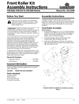
Refer to Figure 5 on page 5:
(#1) Components for 330-228S CW Blade Assembly (Quantities shown are for one Assembly)
3 4 312-075D BLADE SPACER 16 GA
3 4 312-082D BLADE SPACER 18 GA
3 4 312-089D BLADE SPACER 20 GA.
3 4 312-808D BLADE SPACER 24GA
4 4 318-309D BLADE BUSHING
5 1 330-227H BLADE BAR 43"
6 2 802-680C HHCS 1-8 X 4 1/2 PLT GR8
7 2 803-168C NUT HEX TOP LOCK 1-8 PLT
9 2 820-377C CUTTER BLADE 1/2 x 4 x 23.5 FLAT
10 2 820-170C CUTTER BLADE 1/2 x 4 x 23 CW
(#2) Components for 330-302S CCW Blade Assembly (Quantities shown are for one Assembly)
3 4 312-075D BLADE SPACER 16 GA
3 4 312-082D BLADE SPACER 18 GA
3 4 312-089D BLADE SPACER 20 GA.
3 4 312-808D BLADE SPACER 24GA
4 4 318-309D BLADE BUSHING
5 1 330-227H BLADE BAR 43"
6 2 802-680C HHCS 1-8 X 4 1/2 PLT GR8
7 2 803-168C NUT HEX TOP LOCK 1-8 PLT
8 2 820-169C CUTTER BLADE 1/2 x 4 x 23 CCW
9 2 820-377C CUTTER BLADE 1/2 x 4 x 23.5 FLAT
Refer to Figure 14 on page 10:
Components for 330-307L Fixed Blade Assembly (Quantities shown are for all 3 Blade Assemblies)
1 1 330-299H BRACKET, FIXED BLADE LH
2 1 330-300H BRACKET, FIXED BLADE RH
3 1 330-301H BRACKET, FIXED BLADE 20’ CENTER DECK
4 8 802-034C HHCS 1/2-13X1 1/4 GR5
5 1 802-039C HHCS 1/2-13X3 GR5
6 3 802-064C HHCS 3/4-10X2 GR5
7 5 802-082C HHCS 1/2-13X1 3/4 GR5
8 14 803-037C NUT HEX WHIZ 1/2-13 PLT
9 3 803-299C NUT HEX FLG TOP LK 3/4-10 PLT
10 3 820-373C CUTTER BLADE 1/2X4X10.25CW/CCW
Kit No. 330-308A SHREDDER/FIXED BLADE
A maximum of four spacers
are used per assembly.
A maximum of four spacers
are used per assembly.
Refer to Figure 13
15 1 330-585A BAFFLES, REAR (Consist of items 16, 17 & 18)
16 1 330-620K BAFFLE ASSEMBLY, RH REAR
17 1 330-621K BAFFLE ASSEMBLY, LH REAR
18 1 330-622K BAFFLE ASSEMBLY, CENTER REAR
Refer to Figure 10, Figure 11 & Figure 12 on page 8:
Components for 330-585A Rear Baffles (Quantities shown are for all 3 Rear Baffles)
19 1 330-617H REAR BAFFLE RH
20 1 330-618H REAR BAFFLE LH
21 1 330-159D DEFLECTOR CENTER
22 8 802-585C RHSNB 1/2-13X3 1/2 GR5 PLT
23 14 802-106C RHSNB 1/2-13X1 1/2 GR5
24 22 803-037C NUT HEX WHIZ 1/2-13 PLT
Kit No. 330-585A BAFFLES, REAR
Item Qty. Part No. Part Description
Corporate Office: P.O. Box 5060
Salina, Kansas 67402-5060 USA
www.landpride.com
  • Page 1 1
  • Page 2 2
  • Page 3 3
  • Page 4 4
  • Page 5 5
  • Page 6 6
  • Page 7 7
  • Page 8 8
  • Page 9 9
  • Page 10 10
  • Page 11 11
  • Page 12 12

Land Pride RC5020 User manual

Type
User manual

Ask a question and I''ll find the answer in the document

Finding information in a document is now easier with AI