Page is loading ...

REV 3 - 1306270115
L-C2-335
Outdoor Built-in
Gas Grill
Quick Start Guide
3-Installation
Robert H. Peterson Co.
CAUTION: For your safety read the installation instructions and owner’s manual provided with the grill.
These quick start instructions assume a natural gas or household propane confi gured unit. See main instructions for propane cylinder units.
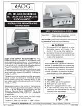
Turn all gas control knobs on the grill to OFF. Attach the fl ex connector coming from the grill to the gas inlet pipe. Open the dedicated manual shut-off
valve. Test for leaks using a half-soap/half-water solution. Slide the unit into position in the enclosure. Do not pinch, kink, or damage the fl ex connector
(Fig. 3-3).
The control panel must be fl ush with the enclosure face as shown in Fig. 3-4.
Proper grill airfl ow must be maintained as shown in Fig. 3-5. Do not block. It is not necessary to remove the control panel or knobs for installation.
OFF
Dedicated manual shut-off valve
y
Cut-out
Countertop
Hanger
Flex
connector
Gas inlet pipe
Top View
Maintain proper ventilation
airfl ow
Fig. 3-4
Control panel
must be fl ush with
enclosure face
Countertop
Overhang
Fig. 3-3
Fig. 3-5
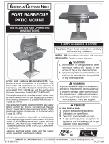
CAUTION: Wind blowing into or across the rear oven lid vent (Fig.
3-1) can cause poor performance and/or dangerous
overheating. Orient the grill so that the prevailing wind
blows toward the front of the grill (Fig. 3-2).
CAUTION: To prevent dangerous overheating, the rear of the unit must have
a minimum clearance of 4” (10.2 cm) from any backsplash/wall.
Fig. 3-2
CORRECT
PLACE GRILL SO PREVAILING WIND
BLOWS TOWARD FRONT OF GRILL
YOU MUST PROTECT REAR OVEN
VENT FROM PREVAILING WIND
Rear oven lid vent
INCORRECT
Fig. 3-1
INSTALLER: Leave these instructions with consumer. CONSUMER: Retain for future reference.
This grill must be installed in accordance with local codes and ordinances, or, in the absence of local codes, with either the latest National Fuel Gas Code (ANSI
Z223.1/NFPA 54), and Natural Gas and Propane Storage and Handling Installation Code (CSA-B149.1).
This appliance and its individual shutoff valves must be disconnected from the gas-supply piping system when testing the system at pressures in excess of ½ psig.
This appliance must be isolated from the gas-supply piping system by closing its dedicated manual shutoff valve during any pressure testing of the gas-supply
system at pressures up to and including ½ psig.
This grill is designed for outdoor use only. DO NOT use this grill under unprotected fl ammable surfaces. DO NOT use this grill inside a building, garage,
enclosed area, or an unprotected covered area (see paragraph below). DO NOT use this grill in or on a recreational vehicle or boat.
Important: When installing this grill in a COMBUSTIBLE surround, an R.H. Peterson insulating liner must be used. See the Fire Magic Insulating
Liner Instructions.
If installed or used under a patio roof, the cooking grid area must be fully covered by an exhaust hood with a vent. An exhaust fan with a rating of 1,000 CFM (cubic feet
per minute) (472 liters per second) or more may be necessary to effectively remove smoke and other cooking by-products from the area under the hood. Fire Magic Vent
Hoods are available to meet this requirement. This outdoor grill must not be used under overhead unprotected combustible construction. THIS UNIT MUST NOT BE
LOCATED IN A FULLY ENCLOSED AREA OF ANY KIND.
2-Unpacking
Carefully unpack the grill, removing all packing material and protective fi lm. Verify that all
parts have arrived undamaged by consulting the parts list in the owner’s manual. Remove
foam packed hardware from oven area. (See Fig. 2-1.)
Consult the parts list in the owner’s manual. If any parts are missing or damaged,
immediately contact the Fire Magic dealer before beginning installation.
Fig. 2-1
1-Safety
Lift out foam packed hardware
Remove plastic
zip-ties
Location
Connect Gas supply
ECHELON
diamond series
NOTE: THE CONTROL PANEL DOES NOT NEED TO BE REMOVED
FOR INSTALLATION. IF REMOVAL IS REQUIRED IT MUST
BE DONE WITH CAUTION BY A QUALIFIED PROFESSIONAL
SERVICE TECHNICIAN, TO PREVENT ANY POSSIBLE WIRE
DISCONNECTIONS.

REV 3 - 1306270115
L-C2-335
5-Test
1. Open the lid and remove any cover(s) of the burner(s) to be lit.
2. Turn all gas control knobs to the OFF position.
3. Turn the gas-supply valve on.
4. Depress the desired control knob for 5 seconds, then, while pressing turn it
counterclockwise to the HI LIGHT position. Once the burner lights, release the control
knob. (Repeat this step for each additional burner.)
CAUTION: If burner does not light within 5 seconds, IMMEDIATELY depress the knob and
turn it to the OFF position. Wait 5 minutes before repeating step 4. If the burner
does not light after repeated attempts, refer to the Lighting Instructions in your
Owners Manual.
4-Grill Setup
Parts Placement Checklist
Place the following items according to their position and orientation
in Fig. 4-1:
Flavor grids, cooking grids, heat zone dividers, backburner cover,
warming rack, meat probe.
Leave pre-installed E-burners in place to maintain proper alignment.
Backburner Cover
Hook the backburner cover over the top of the backburner to protect
the backburner from grease, dust and dirt when it is not in use.
Remove cover before use.
Warming Rack
The warming rack comes pre-installed. Remove zip ties before use.
Consult the owner’s manual to remove or replace.
Fig. 4-1
Cooking Grid
Flavor Grid
(not with IR)
E-burner
*
(comes pre-
installed)
Backburner
cover
Warming
rack
Power Hood motor
assembly box (optional)
Front support
adjustment
screws (2)
Note: For infrared burner equipped grills, see
detailed instructions included in your
owners manual.
Power supply
Heat zone
divider
Drip tray
(with lighting instructions)
Backburner
Drip tray
liners
Fig. 5-2
Left
main burner control
knob
Right
main burner
control knob
Digital
thermometer
Center right main
burner
control knob
Center left main
burner
control knob
Smoker drawer
burner control
knob
Power hood
control switch
(if equipped)
Right backburner
control knob
(if equipped)
Left back-
burner
control knob
(if equipped)
Pull-out drip
tray
Meat
probe
Wood chip
tray
Fig. 5-1 - Burner valve control knob
6-Propane Safety
FOR PROPANE CONFIGURATIONS; READ ALL SAFETY INSTRUCTIONS AND WARNINGS REGARDING THE USE OF PROPANE
GAS FOUND IN YOUR OWNERS MANUAL.
Wood chip
tray
WHEN OPERATING THIS
APPLIANCE WITH PROPANE, ALL
INSTRUCTIONS AND WARNINGS
MUST BE OBSERVED. FAILURE TO
DO SO MAY RESULT IN A FIRE OR
EXPLOSION CAUSING SERIOUS
INJURY OR DEATH.
OFF
HI
LIGHT
LOW
TO
TURN OFF
T O TURN ON
Read setting
here
HIGH to
LIGHT
Read setting here
(OFF position shown)
To Turn OFF
To Turn ON
Use
HI (high)
to light
Press
knob in
to turn
Gas Flow
Indicator
For your convenience and safety;
when the control knob is in the
ON position, the gas fl ow indicator
will change from blue to red. (Red
indicates gas fl ow.) See Fig. 5-1.
Master
switch
The master switch (Fig. 5-2) controls
the power to all lights, igniters, and the
thermometer. It allows the power to be
turned on or off for safety and convenience.
The switch will need to be turned on prior to
each grill use, and turned off after each use.
*
The burner ports
and carry-over slots
must be kept clean to
ensure proper ignition
and operation.
/