Vega VEGAMET 142 Product information

Type
Product information
Product information
Controllers and communication
Controllers in eld housing for continuously measuring level
sensors
VEGAMET 141, 142
VEGAMET 341, 342
VEGAMET 841, 842
VEGAMET 861, 862
Document ID: 62826
2
Contents
Controllers and communication
62826-US-210330
Contents
1 Product description ............................................................................................................................................................................................... 3
2 Type overview .........................................................................................................................................................................................................4
3 Instrument selection .............................................................................................................................................................................................. 7
4 Selection criteria .................................................................................................................................................................................................... 8
5 Mounting ............................................................................................................................................................................................................... 13
6 Electrical connection ...........................................................................................................................................................................................15
7 Adjustment ........................................................................................................................................................................................................... 18
8 Dimensions ...........................................................................................................................................................................................................19
Take note of safety instructions for Ex applications
Please note the Ex specic safety information which you can nd on our homepage www.vega.com/downloads under " Approvals" and which
comes with every instrument. In hazardous areas you should take note of the corresponding regulations, conformity and type approval certicates
of the sensors and power supply units. The sensors must only be operated on intrinsically safe circuits. The permissible electrical values are stated
in the certicate.
3
Product description
Controllers and communication
62826-US-210330
1 Product description
Functional principle
In continuous measurement, for example, the level in a vessel is detected
by a sensor and then transferred to a controller for further processing. By
means of an adjustment in the controller, the measured value can be adapt-
ed to the individual circumstances. The requested measurement parameter
is indicated in the display via a scaling/linearisation. The measured value
can be transmitted additionally to a connected control system or visualisa-
tion via the current output.
Several operating relays are additionally integrated in each VEGAMET for
level detection. These can be used to control pumps or other actuators.
Application
The controllers can be used in connection with the appropriate sensors for
a large number of measuring tasks. Preset applications and functions are
already integrated for convenient set-up which can be selected and adapt-
ed very easily by means of an application wizard.
The following applications and functions are available, for example, de-
pending on the instrument type:
Universal
Level storage tank
Calculation dierence
Calculation total
Calculation average value
Wells
Pumping station
Sewage screw lifting station
Density
Overow basin
Screen control
Flow measurement ume/weir
Pressurized vessel
Measured value memory/data logger
All instruments also serve as a (Ex) power supply unit for the connected
sensors. Power is supplied via the same two-wire cable. As an option in
the non-Ex versions, an input without sensor power supply (passive input)
is available, enabling the connection of transmitters with their own voltage
supply (sensors in four-wire version). Depending on the instrument type,
one or two independent sensors can be connected and their measured
values processed.
Safety
The integrated function monitoring detects faults in the controller as well as
in the connected sensors. If such a fault is detected, the integrated fail safe
relay de-energises (safe status) and a fault signal is output via the LEDs on
the front panel. In addition, the current output of each VEGAMET jumps to
an adjustable fault current.
The instrument has the following approvals:
Ex approval as auxiliary, intrinsically safe instrument
Ship approval for the VEGAMET series 100/300
Certicate as WHG-conform limit signal transmitter
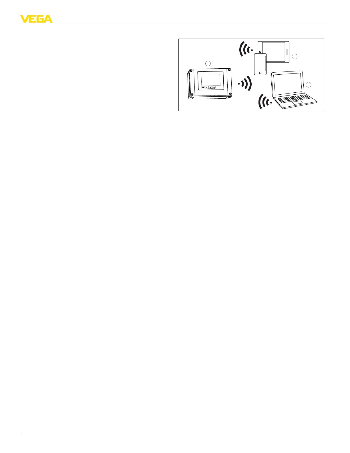
Adjustment
All devices can be operated on site via the integrated display and adjust-
ment unit. Wireless operation via Bluetooth using the following adjustment
tools is also possible:
Smartphone/tablet (iOS or Android operating system)
PC/notebook with Bluetooth LE or Bluetooth USB adapter (Windows
operating system)
1
3
2
Fig. 1: Wireless connection to smartphone/table/notebook
1 VEGAMET
2 Smartphone/Tablet
3 PC/Notebook
4
Type overview
Controllers and communication
62826-US-210330
2 Type overview
VEGAMET 141 VEGAMET 142
Mounting Carrier rail mounting Carrier rail mounting
Application
Level/gauge measurement
Wells
Pumping station
Sewage screw lifting station
Process pressure measurement
Flow measurement
Level/gauge measurement
Wells
Pumping station
Sewage screw lifting station
Flow measurement
Density
Overow basin
Screen control
Pressurized vessel
Calculation dierence/sum/average
Measurement loops 1 Measurement loop 2 measuring loops, 1 arithmetic measur-
ing loop
Sensor inputs 1 x 4 … 20 mA 2 x 4 … 20 mA
Digital inputs - -
Outputs
3 x operating relay, one can be cong-
ured as fail safe relay
1 x current output
3 x operating relay, one can be cong-
ured as fail safe relay
2 x current outputs
Display on the instrument
Graphic-capable LC display, with lighting
LEDs for operation, relays, fault signal
Congurable status indication via dis-
play background lighting
Graphic-capable LC display, with lighting
LEDs for operation, relays, fault signal
Congurable status indication via dis-
play background lighting
Measured value memory - -
Interfaces Bluetooth LE Bluetooth LE
Ambient temperature -40 … +60 °C (-40 … +140 °F) -40 … +60 °C (-40 … +140 °F)
5
Type overview
Controllers and communication
62826-US-210330
VEGAMET 341 VEGAMET 342
Mounting Panel mounting Panel mounting
Application
Level/gauge measurement
Wells
Pumping station
Sewage screw lifting station
Process pressure measurement
Flow measurement
Level/gauge measurement
Wells
Pumping station
Sewage screw lifting station
Flow measurement
Density
Overow basin
Screen control
Pressurized vessel
Calculation dierence/sum/average
Measurement loops 1 Measurement loop 2 measuring loops, 1 arithmetic measur-
ing loop
Sensor inputs 1 x 4 … 20 mA 2 x 4 … 20 mA
Digital inputs - -
Outputs
3 x operating relay, one can be cong-
ured as fail safe relay
1 x current output
3 x operating relay, one can be cong-
ured as fail safe relay
2 x current outputs
Display on the instrument
Graphic-capable LC display, with lighting
LEDs for operation, relays, fault signal
Congurable status indication via dis-
play background lighting
Graphic-capable LC display, with lighting
LEDs for operation, relays, fault signal
Congurable status indication via dis-
play background lighting
Measured value memory - -
Interfaces Bluetooth LE Bluetooth LE
Ambient temperature -40 … +60 °C (-40 … +140 °F) -40 … +60 °C (-40 … +140 °F)
VEGAMET 841 VEGAMET 842
Mounting Wall/pipe assembly Wall/pipe assembly
Application
Level/gauge measurement
Wells
Pumping station
Sewage screw lifting station
Process pressure measurement
Flow measurement
Level/gauge measurement
Wells
Pumping station
Sewage screw lifting station
Flow measurement
Density
Overow basin
Screen control
Pressurized vessel
Calculation dierence/sum/average
Measurement loops 1 Measurement loop 2 measuring loops, 1 arithmetic measur-
ing loop
Sensor inputs 1 x 4 … 20 mA 2 x 4 … 20 mA
Digital inputs - -
Outputs
3 x operating relay, one can be cong-
ured as fail safe relay
1 x current output
3 x operating relay, one can be cong-
ured as fail safe relay
2 x current outputs
Display on the instrument
Graphic-capable LC display, with lighting
LEDs for operation, relays, fault signal
Congurable status indication via dis-
play background lighting
Graphic-capable LC display, with lighting
LEDs for operation, relays, fault signal
Congurable status indication via dis-
play background lighting
Measured value memory - -
Interfaces Bluetooth LE Bluetooth LE
Ambient temperature -40 … +60 °C (-40 … +140 °F) -40 … +60 °C (-40 … +140 °F)
6
Type overview
Controllers and communication
62826-US-210330
VEGAMET 861 VEGAMET 862
Mounting Wall/pipe assembly Wall/pipe assembly
Application
Level/gauge measurement
Wells
Pumping station
Sewage screw lifting station
Process pressure measurement
Flow measurement
Level/gauge measurement
Wells
Pumping station
Sewage screw lifting station
Flow measurement
Density
Overow basin
Screen control
Pressurized vessel
Calculation dierence/sum/average
Measurement loops 1 Measurement loop 2 measuring points, 1 dierential measur-
ing point
Sensor inputs 1 x 4 … 20 mA/HART 2 x 4 … 20 mA/HART
Digital inputs 2 Digital inputs 4 Digital inputs
Outputs
4 x operating relay, one can be cong-
ured as fail safe relay
1 x current output
6 x operating relay, one can be cong-
ured as fail safe relay
3 x current output
Display on the instrument
Graphic-capable LC display, with lighting
LEDs for operation, relays, fault signal
Congurable status indication via dis-
play background lighting
Graphic-capable LC display, with lighting
LEDs for operation, relays, fault signal
Congurable status indication via dis-
play background lighting
Measured value memory Internal memory and SD card Internal memory and SD card
Interfaces Bluetooth LE Bluetooth LE
Ambient temperature -40 … +60 °C (-40 … +140 °F) -40 … +60 °C (-40 … +140 °F)
7
Instrument selection
Controllers and communication
62826-US-210330
3 Instrument selection
All controllers of the 100, 300 and 800 instrument series power the con-
nected sensors, process the measured values and display these on the
integrated display and adjustment unit. Up to two 4 … 20 mA or 4 … 20 mA/
HART sensors can be connected depending on the instrument version.
The instruments enable simple implementation of pump controls, ow
measurements on open channels and weirs, totalizers, dierence, sum
and average value calculations. Limit values can be reliably monitored and
relays can be switched, e.g. for an overll protection according to WHG.
All instruments have a graphic display with background lighting. This serves
at the same time as a status display visible from a great distance. The
background lighting changes in he delivery status according to NAMUR NE
107 (e. g. red for fault, orange for function check). Alternatively, the status
display can also be congured based on the relay or the measured value.
When the measured value is used, for example, up to ve operating states
can be signalled depending on the level.
The three instrument series 100, 300 and 800 dier mainly in the protection
rating and the assembly possibilities and thus also in the housing.
VEGAMET series 100
The compact series is ideal for mounting on rails, e.g. in switch cabinets. A
graphic display for on-site data visualisation and checking as well as a turn/
oush button for simple on-site adjustment are integrated.
VEGAMET series 300
The built-in housing is ideal for mounting in the panel or switch cabinet
door. A large graphic display for on-site data visualisation and checking as
well as a turn/push button for simple on-site adjustment are integrated.
VEGAMET series 800
The housings are designed for wall/pipe assembly and harsh eld condi-
tions, e.g. outdoors. A large graphic display for on-site data visualisation
and checking as well as push buttons for easy on-site adjustment are
integrated.
The VEGAMET 861/862 has 4 … 20 mA/HART sensor inputs. Digital inputs
and a measured value memory/data logger are additionally available.
8
Selection criteria
Controllers and communication
62826-US-210330
4 Selection criteria
The following charts provide an overview of the standard applications and functions of the controllers. They also give information about whether the respective function can be
activated and adjusted via the integrated indicating and adjustment unit (OP) or via DTM/app.
1)
VEGAMET 141, 142
Applications (adjustable with DTM/app) VEGAMET Adjustment
141 142 OP DTM/App
Universal
Level - storage tank
Calculation Dierence
Total
Average value
Wells
Pumping station
Sewage screw lifting station
Screen control
Flow measurement - ume/weir
Pressurized vessel
Additional application examples VEGAMET Adjustment
141 142 OP DTM/App
Level measurement
Gauge measurement
Process pressure measurement
Overow basin
Density
Functions VEGAMET Adjustment
141 142 OP DTM/App
Application wizard
Indication measured values
Automatic display change
Congurable status indication via background lighting of the display
Display multilingual
Sensor input - 4 … 20 mA
Damping
Linearisation Predened curves
Dimensions - ISO standard
Flow formula
Manufacturer denition
Calculation wizard
Locating chart
Measure
Import
Adjustment of the measuring point
Scaling
Totalizer 1/2
Totalizer 3/4/5/6
1)
OP: Operating Panel (integrated display and adjustment unit)
9
Selection criteria
Controllers and communication
62826-US-210330
Functions VEGAMET Adjustment
141 142 OP DTM/App
Relay mode Overll protection
Dry run protection
Switching window ON
Switching window OFF
Flow volume pulse
Sampling pulse
Tendency increasing
Tendency decreasing
Pump control 1 (same running time)
Pump control 2 (same running time)
Pump control 3 (xed order)
Pump control 4 (xed order)
Mode Pump control - sequenced operation
Pump control - alternating pump operation
Dry weather pump
Forced pump changeover
Relay switch on and o delay
Bandwidth for switching points
Fail safe relay
Current output 0/4 … 20 mA, 20 … 4 mA
Flow volume pulse
Sampling pulse
Diagnostics Status
Measured values
Simulation Sensor value, %, lin% value, scaled values
Current output
Relay output
Protection of the parameterization
Bluetooth access code
Activate/deactivate Bluetooth communication
VEGAMET 341, 342
Applications (adjustable with DTM/app) VEGAMET Adjustment
341 342 OP DTM/App
Universal
Level - storage tank
Calculation Dierence
Total
Average value
Wells
Pumping station
Sewage screw lifting station
Screen control
Flow measurement - ume/weir
Pressurized vessel
Additional application examples VEGAMET Adjustment
341 342 OP DTM/App
Level measurement
Gauge measurement
Process pressure measurement
Overow basin
10
Selection criteria
Controllers and communication
62826-US-210330
Additional application examples VEGAMET Adjustment
341 342 OP DTM/App
Density
Functions VEGAMET Adjustment
341 342 OP DTM/App
Application wizard
Indication measured values
Automatic display change
Congurable status indication via background lighting of the display
Display multilingual
Sensor input - 4 … 20 mA
Damping
Linearisation Predened curves
Dimensions - ISO standard
Flow formula
Manufacturer denition
Calculation wizard
Locating chart
Measure
Linearization curves - Import
Adjustment of the measuring point
Scaling
Totalizer 1/2
Totalizer 3/4/5/6
Relay mode Overll protection
Dry run protection
Switching window ON
Switching window OFF
Flow volume pulse
Sampling pulse
Tendency increasing
Tendency decreasing
Pump control 1 (same running time)
Pump control 2 (same running time)
Pump control 3 (xed order)
Pump control 4 (xed order)
Mode Pump control - sequenced operation
Pump control - alternating pump operation
Dry weather pump
Forced pump changeover
Relay switch on and o delay
Bandwidth for switching points
Fail safe relay
Current output 0/4 … 20 mA, 20 … 4 mA
Flow volume pulse
Sampling pulse
Diagnostics Status
Measured values
Simulation Sensor value, %, lin% value, scaled values
Current output
Relay output
Protection of the parameterization
Bluetooth access code
11
Selection criteria
Controllers and communication
62826-US-210330
Functions VEGAMET Adjustment
341 342 OP DTM/App
Activate/deactivate Bluetooth communication
VEGAMET 841, 842, 861, 862
Applications (adjustable with DTM/app) VEGAMET Adjustment
841 842 861 862 OP DTM/App
Universal
Level - storage tank
Calculation - dierence
Flow measurement - ume/weir
Pumping station
Screen control
Sewage screw lifting station
Additional application examples VEGAMET Adjustment
841 842 861 862 OP DTM/App
Level measurement
Gauge measurement
Process pressure measurement
Functions VEGAMET Adjustment
841 842 861 862 OP DTM/App
Application wizard
Indication measured values
Automatic display change
Congurable status indication via background lighting of the display
Display multilingual
Sensor input 4 … 20 mA
HART
Damping
Linearisation Predened curves
Dimensions - ISO standard
Flow formula
Manufacturer denition
Calculation wizard
Locating chart
Measure
Import linearization curves
Adjustment of the measuring point
Scaling
Totalizer 1/2
Totalizer 3/4
12
Selection criteria
Controllers and communication
62826-US-210330
Functions VEGAMET Adjustment
841 842 861 862 OP DTM/App
Relay mode Overll protection
Dry run protection
Switching window ON
Switching window OFF
Flow volume pulse
Sampling pulse
Tendency increasing
Tendency decreasing
Pump control 1 (same running time)
Pump control 2 (same running time)
Pump control 3 (xed order)
Pump control 4 (xed order)
Mode Pump control - sequenced operation
Pump control - alternating pump operation
Dry weather pump
Pump monitoring
Forced pump changeover
Relay - Switch on and o delay
Bandwidth for switching points
Fail safe relay
Current output 0/4 … 20 mA, 20 … 4 mA
Flow volume pulse
Sampling pulse
Diagnostics Status
Measured values
Simulation Sensor value, %, lin% value, scaled values
Current output
Relay output
Digital input
Date/Time
Internal device memory/SD card
Protection of the parameterization
Bluetooth access code
13
Mounting
Controllers and communication
62826-US-210330
5 Mounting
5.1 VEGAMET 141, 142
Mounting options
VEGAMET is designed for carrier rail mounting (top hat rail 35 x 7.5
according to DIN EN 50022/60715). Due to its protection rating of IP20,
the instrument is suitable for mounting in switching cabinets. It must be
mounted vertically.
A VEGAMET in Ex version is an auxiliary, intrinsically safe instru-
ment and may not be installed in explosion-endangered areas.
5.2 VEGAMET 341, 342
Mounting options
The device is designed for recessed installation in a switching cabi-
net, housing front panel or switch cabinet door. The required cut-out is
92 x 92 mm (3.63 x 3.63 in) according to IEC 61554.
A VEGAMET in Ex version is an auxiliary, intrinsically safe instru-
ment and may not be installed in explosion-endangered areas.
Front panel mounting
Make sure that the cut-out required for mounting has a size of 92 x 92 mm
(3.63 x 3.63 in).
Slide the device into the panel cut-out from the front.
Press the two tensioning elements into the provided gaps.
Screw in the two screws of the tensioning elements evenly with a screw-
driver.
3
2
1
Fig. 2: Front panel mounting
1 Front panel, front plate or switching cabinet door
2 Clamping elements
3 Slotted screw
5.3 VEGAMET 841, 842, 861, 862
Mounting options
The eld housing of the VEGAMET is equally suitable for outdoor or indoor
installation due to its degree of protection IP66/IP67 and Type 4X. The
standard version is designed for wall mounting. A mounting adapter for pipe
mounting is available as an option.
Wall mounting
Fix the mounting plate to the wall using the screws and dowels supplied as
shown in the gure below. Make sure that the arrows on the mounting plate
point upwards.
Loosen the four screws in the housing cover and open it to the left. Fasten
the device to the mounting plate using the screws (M5) supplied.
82 mm
(3.23")
ø13 mm
(0.51")
ø7 mm
(0.28")
82 mm
(3.23")
Fig. 3: Mounting plate for wall mounting (VEGAMET 841, 842)
82 mm
(3.23")
150 mm
5.91")
82 mm
(3.23")
108 mm
(4.25")
ø13 mm
(0.51")
ø7 mm
(0.28")
Fig. 4: Mounting plate for wall mounting (VEGAMET 861, 862)
Tube mounting
The optionally available mounting accessories are required for tube mount-
ing. The kit consists of two pairs of mounting brackets and four mounting
screws M6 x 100.
The mounting brackets are screwed to the mounting plate and the tube as
shown in the following illustration.
Loosen the four screws in the housing cover and open it to the left. Fasten
the device to the mounting plate using the screws (M5) supplied.
4321
5
Fig. 5: Tube mounting
1 VEGAMET
2 Mounting plate
3 4 screws M6 x 100
4 Mounting brackets
5 Pipe for diameter 29 … 60 mm (1.14" to 2.36")
14
Mounting
Controllers and communication
62826-US-210330
Mounting sun shade
The optional sun protection can be used to protect against direct sunlight.
The sunshade is simply mounted between the mounting plate and the
controller, this is possible for both wall and pipe mounting.
5432
1
6
Fig. 6: Mounting sun protection with pipe mounting
1 VEGAMET
2 Sun shade
3 Mounting plate
4 4 screws M6 x 100
5 Mounting brackets
6 Pipe for diameter 29 … 60 mm (1.14" to 2.36")
15
Electrical connection
Controllers and communication
62826-US-210330
6 Electrical connection
6.1 Preparing the connection
Safety instructions
Always keep in mind the following safety instructions:
The electrical connection must only be carried out by trained, qualied
personnel authorised by the plant operator.
If overvoltage surges are expected, overvoltage arresters should be
installed.
Warning:
Only connect or disconnect in de-energized state.
6.2 Connection VEGAMET 141
67 68 69
64 65 66
61 62 63
1 2 3
41 42
+ -
91 92
L+ N-
1
3
4
7
6
5
2
Fig. 7: Wiring plan VEGAMET 141
1 Sensor input (active/passive)
2)
2 HART sockets for connection of a VEGACONNECT
3 4 … 20 mA current output
4 Voltage supply of the controller
5 Relay output 1
6 Relay output 2
7 Relay output 3
6.3 Connection VEGAMET 142
67 68 69
64 65 66
61 62 63
4 5
1 2
6
3
41 42
+ -
43 44
+-
91 92
L+ N-
1
2
5
6
7
10
9
8
3
4
Fig. 8: Wiring plan VEGAMET 142
1 Sensor input 1 (active/passive)
3)
2 Sensor input 2 (active/passive)
4)
3 HART sockets input 1 for connection of a VEGACONNECT
4 HART sockets input 2 for connection of a VEGACONNECT
5 4 … 20 mA current output 1
6 4 … 20 mA current output 2
7 Voltage supply of the controller
8 Relay output 1
9 Relay output 2
10 Relay output 3
2)
Passive input not available for Ex version
3)
Passive input 1 not available for Ex version
4)
Passive input 2 not available for Ex version
16
Electrical connection
Controllers and communication
62826-US-210330
6.4 Connection VEGAMET 341
+
-
L+
N-
4
5
6
3
2
1
3
92
91
42
41
2
16
1
62
63
64
65
66
67
68
69
Fig. 9: Wiring plan VEGAMET 341
1 Sensor input (active/passive) and HART sockets for connecting a VEGACON-
NECT
5)
2 Voltage supply of the controller
3 4 … 20 mA current output
4 Relay output 1
5 Relay output 2
6 Relay output 3
6.5 Connection VEGAMET 342
+
-
L+
N-
6
7
8
4
3
1
3
92
91
42
41
+
-
5
44
43
2
1
2
6
5
4
61
62
63
64
65
66
67
68
69
Fig. 10: Wiring plan VEGAMET 342
1 Sensor input 1 (active/passive)
6)
2 Sensor input 2 (active/passive)
7)
3 Voltage supply of the controller
4 4 … 20 mA current output 1
5 4 … 20 mA current output 2
6 Relay output 1
7 Relay output 2
8 Relay output 3
6.6 Connection VEGAMET 841
91 92
LN
+- +-
61 62 63 64 65 66 67 68 69
41 42
123
Power 32
1S
ensor
Relay Output
Output
Current
1 2
3
4
5
Fig. 11: Wiring plan VEGAMET
1 Voltage supply of the controller
2 Relay outputs 1 … 3
3 Current output
4 Sensor input (active/passive)
5 Ground terminal for protective conductor
Details on the electrical connection can be found in the operating
instructions of the device in the download area on our homepage.
6.7 Connection VEGAMET 842
12
91 92
LN
+- +-+-
61 62 63 64 65 66 67 68 69
41 42 43 44
123
456
Power 321
Sensor 1
Relay OutputOutput
Current
Sensor 2
1 2
3
5
4
Fig. 12: Wiring plan VEGAMET
1 Voltage supply of the controller
2 Relay outputs 1 … 3
3 Current outputs 1/2
4 Sensor inputs 1/2 (active/passive)
5 Ground terminal for protective conductor
Details on the electrical connection can be found in the operating
instructions of the device in the download area on our homepage.
5)
Passive input not available for Ex version
6)
Passive input 1 not available for Ex version
7)
Passive input 2 not available for Ex version
17
Electrical connection
Controllers and communication
62826-US-210330
6.8 Connection VEGAMET 861
12
1
212223
91 92
LN
+- +-
61 62 63 64 65 66 67 68 69 70 71 72 41 42 123
24 2526
Power
432
1S
ensor 1
Relay Output
Output
Current
Digital IN
5
1 2 3
6 7
8
4
Fig. 13: Wiring plan VEGAMET
1 Voltage supply of the controller
2 Relay outputs 1 … 4
3 Current output
4 Sensor input (active/passive)
5 Digital inputs 1/2
6 Ground terminal for protective conductor
7 Ground terminal for cable screening sensor cable
8 Ground terminal for potential equalization
6.9 Connection VEGAMET 862
12 3
12 3
4
212223
91 92
LN
+- +-+-+-
61 62 63 64 65 66 67 68 69 70 71 72 73 74 75 76 77 78 41 42 43 44 45 46 123
456
24 2526 27282930 3132
Power
65432
1S
ensor 1
Relay Output Current Output
Digital IN
Sensor 2
5
1 2 3
6 7
4
8
Fig. 14: Wiring plan VEGAMET
1 Voltage supply of the controller
2 Relay outputs 1 … 6
3 Current outputs 1 … 3
4 Sensor inputs 1/2 (active/passive)
5 Digital inputs 1 … 4
6 Ground terminal for protective conductor
7 Ground terminal for cable screening
8 Ground terminal for potential equalization
18
Adjustment
Controllers and communication
62826-US-210330
7 Adjustment
7.1 Adjustment options and access protection
All controllers have an integrated display and adjustment unit. In addition,
the instruments can be parameterised via Bluetooth and corresponding
adjustment tools.
Adjustment via the display and adjustment unit
The adjustment is carried out menu-driven via four front keys or a turn/
push button as well as a clearly arranged, graphic-capable LC-display with
background lighting.
Wireless adjustment via Bluetooth
The integrated Bluetooth module enables wireless connection to smart-
phones/tablets (iOS/Android) or Windows PCs.
Operation is via a free app from the " Apple App Store", the " Goo-
gle Play Store" or the " Baidu Store". Alternatively, adjustment can also be
carried out via PACTware/DTM and a Windows PC.
Fig. 15: Wireless connection to smartphone/table/notebook
Information:
Certain setting options are not possible or only possible to a limited
extent on site with the integrated display and adjustment unit, for
example the settings for ow measurement or pump control. For
these applications, the use of PACTware/DTM or the VEGA Tools
app is recommended. An overview of the available applications
and functions as well as their adjustment options can be found in
chapter " Selection criteria".
Access protection
Devices with a Bluetooth radio interface are protected against unwanted
access from outside. This means that only authorized persons can receive
measured and status values and change device settings via this interface.
Protection of the parameterization
The settings (parameters) of the device can be protected against unwanted
changes. The parameter protection is deactivated on delivery, all settings
can be made.
19
Dimensions
Controllers and communication
62826-US-210330
8 Dimensions
VEGAMET 141, 142
56 mm
(2.20")
40 mm
(1.57")
113 mm
(4.45")
121 mm
(4.76")
108 mm
(4.25")
46 mm
(1.81")
92 mm
(3.62")
52 mm
(2.05")
Fig. 16: Dimensions VEGAMET 141
56 mm
(2.20")
40 mm
(1.57")
113 mm
(4.45")
121 mm
(4.76")
111 mm
(4.37")
46 mm
(1.81")
92 mm
(3.62")
55 mm
(2.17")
Fig. 17: Dimensions VEGAMET 142
VEGAMET 341, 342
96 mm
(3.78")
111 mm
(4.37")
18 mm
(0.71")
150 mm
(5.91")
35 mm
(1.38")
96 mm
(3.78")
Fig. 18: Dimensions VEGAMET 341
96 mm
(3.78")
111 mm
(4.37")
18 mm
(0.71")
150 mm
(5.91")
35 mm
(1.38")
96 mm
(3.78")
Fig. 19: Dimensions VEGAMET 342
VEGAMET 841, 842
162 mm
(6.38")
76 mm
(2.99")
111 mm
(4.37")
Fig. 20: Dimensions VEGAMET 841, 842
82 mm
(3.23")
11 mm
(0.43")
160 mm
(6.30")
82 mm
(3.23")
104 mm
(4.09")
ø13 mm
(0.51")
ø7 mm
(0.27")
Fig. 21: Dimensions Wall mounting VEGAMET 841, 842
82 mm
(3.23")
142 mm
(5.59")
198 mm
(7.80")
71 mm
(2.76")
82 mm
(3.23")
ca. 141 mm
(5.55")
ca. 177 mm
(6.97")
Fig. 22: Dimensions Sun shade VEGAMET 841, 842
ø 29...60 mm
(1.14"...2.36")
82 mm
(3.23")
15 mm
(0.59")
97 mm
(3.82")
20 mm
(0.79")
M6
2 mm
(0.08")
20 mm
(0.79")
2 mm
(0.08")
20 mm
(0.79")
48...84 mm
(1.89"...3.31")
Fig. 23: Dimensions Brackets for tube mounting VEGAMET 841, 842
20
Dimensions
Controllers and communication
62826-US-210330
VEGAMET 861, 862
200 mm
(7.87")
89,5 mm
(3.52")
136 mm
(5.35")
Fig. 24: Dimensions VEGAMET 861, 862
82 mm
(3.23")
11 mm
(0.43")
150 mm
5.91")
198 mm
(7.79")
82 mm
(3.23")
108 mm
(4.25")
128 mm
(5.04")
ø13 mm
(0.51")
ø7 mm
(0.27")
Fig. 25: Dimensions Wall mounting VEGAMET 861, 862
82 mm
(3.23")
150 mm
(5.91")
250 mm
(9.84")
82 mm
(3.23")
108 mm
(4.25")
ca. 178 mm
(7.01")
217 mm
(8.54")
Fig. 26: Dimensions Sun shade VEGAMET 861, 862
ø 29...60 mm
(1.14"...2.36")
82 mm
(3.23")
15 mm
(0.59")
97 mm
(3.82")
20 mm
(0.79")
M6
2 mm
(0.08")
20 mm
(0.79")
2 mm
(0.08")
20 mm
(0.79")
48...84 mm
(1.89"...3.31")
Fig. 27: Dimensions Brackets for tube mounting VEGAMET 861, 862
  • Page 1 1
  • Page 2 2
  • Page 3 3
  • Page 4 4
  • Page 5 5
  • Page 6 6
  • Page 7 7
  • Page 8 8
  • Page 9 9
  • Page 10 10
  • Page 11 11
  • Page 12 12
  • Page 13 13
  • Page 14 14
  • Page 15 15
  • Page 16 16
  • Page 17 17
  • Page 18 18
  • Page 19 19
  • Page 20 20
  • Page 21 21
  • Page 22 22
  • Page 23 23
  • Page 24 24

Vega VEGAMET 142 Product information

Type
Product information

Ask a question and I''ll find the answer in the document

Finding information in a document is now easier with AI