
EN
MSBUS expansion modules / Rev.B 0.02 – 1
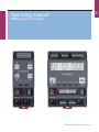
Operating manual
MSBUS expansion modules

2 – MSBUS expansion modules / Rev.B 0.02 MSBUS expansion modules / Rev.B 0.02 – 3
2 – MSBUS expansion modules / Rev.B 0.02
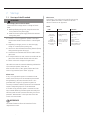
1. Contents
1. Contents. . . . . . . . . . . . . . . . . . . . . . . . . . . . . 2
2. Information in this document . . . . . . . . . . . . 2
3. General safety instructions . . . . . . . . . . . . . . 3
4. Product overview. . . . . . . . . . . . . . . . . . . . . . 4
4.1 Versions ...........................4
4.2 ES module [EM 184]..................5
4.3 I/O module [EM 172] .................5
5. Installation of the ES module . . . . . . . . . . . . 6
5.1 DIP switch 1 setting ..................6
5.2 DIP switch 2 setting ..................6
5.3 Connection of module to gate control .....6
5.4 Connectionofdraw-inprotectionPNPMFZ 6
5.5 Connection of draw-in protection OSE ....7
5.6 Connection of draw-in protection with relay
output ............................7
6. Installation of the I/O module . . . . . . . . . . . . 8
6.1 Connection of I/O module to gate control ..8
6.2 Connectionofprogrammableinput11/15
and 12 / 16 (XB53A)..................8
6.3 Connectionofprogrammableinput13/17
and 14 / 18 (XB53B)..................8
6.4 Connectionofprogrammableoutput11/15
and 12 / 16 (XH13)...................8
6.5 Connectionofprogrammableoutput13/17
(XH19A)...........................9
6.6 Connectionofprogrammableoutput14/18
(XH19B) ...........................9
7. Start-up . . . . . . . . . . . . . . . . . . . . . . . . . . . . 10
7.1 Start-up of the ES module.............10
7.2 I/O module start-up .................11
8. Technical data . . . . . . . . . . . . . . . . . . . . . . . 13
8.1 Technical data for the ES module .......13
8.2 Technical data for the I/O module .......13
9. Maintenance . . . . . . . . . . . . . . . . . . . . . . . . 14
10. Manufacturer‘s Declaration . . . . . . . . . . . . . 15
Original operating instructions
− Copyright.
− No part of these instructions may be reproduced without
our prior approval.
− Subject to alterations in the interest of technical progress.
− All dimensions given in mm.
− The diagrams in this manual are not to scale.
Key to symbols
WARNING!
Indicates a hazard with a medium level of risk which, if not
avoided, could result in death or serious injury.
CAUTION!
Indicates a hazard with a low level of risk which, if not
avoided, could result in minor or moderate injury.
ATTENTION!
Indicates an imminent danger of damage or destruction.
CHECK
Indicates a check to be performed.
REFERENCE
Reference to separate documents which must be complied
with.
☞ Action request
− List, itemisation
➔ Reference to other sections of this document
2. Information in this document

2 – MSBUS expansion modules / Rev.B 0.02 MSBUS expansion modules / Rev.B 0.02 – 3
EN
3. General safety instructions
WARNING!
Failure to comply with the documentation could
result in life-threatening danger!
☞ Be sure to follow all the safety instructions in this
document.
Warranty
The function and safety of the equipment is only guaranteed
if the warning and safety instructions included in these
operating instructions are adhered to.
The manufacturer is not liable for personal injury or damage
to property if these occur as a result of the warnings and
safety advice being disregarded.
The manufacturer does not accept any liability or warranty
for damage due to the use of non-approved spare parts and
accessories.
Use for the intended purpose
The expansion module expands a control with MSBUS.
Target group
Onlyqualiedandtrainedelectriciansmayconnect,
programme and service the control.
Qualiedandtrainedelectriciansmustmeetthefollowing
requirements:
− Knowledgeofthegeneralandspecicsafetyandaccident
prevention regulations
− Knowledge of the relevant electrical regulations
− Training in the use and care of appropriate safety
equipment
− Capable of recognising the dangers associated with
electricity
Instructions regarding installation and connection
− The control is designed with X type terminals.
− The system must be disconnected from the electricity supply
before carrying out any electrical work. It must be ensured
that the electricity supply remains disconnected for the
duration of the work.
− Local protective regulations must be complied with.
− Consultthemanufacturerbeforecarryingoutmodications
or replacing the mains connection cable.
Information concerning operation
− Unauthorised persons (particularly children) should not be
allowed to play with permanently installed adjusting or
control devices.
− Keep remote controls beyond the reach of children.
Regulations and bases for testing
Forconnecting,programmingandservicing,thefollowing
regulations must be observed (the list is not exhaustive).
Construction product standards
− EN13241-1(Productswithoutreresistanceorsmoke
control characteristics)
− EN 12445 (Safety in use of power operated doors -
Test methods)
− EN 12453 (Safety in use of power operated doors -
Requirements)
− EN 12978 (Safety devices for power operated doors and
gates - Requirements and test methods)
EMC
− EN 55014-1 (Radio disturbance, household appliances)
− EN 61000-3-2 (Disturbances in supply systems - harmonic
currents)
− EN 61000-3-3 (Disturbances in supply systems - voltage
uctuations)
− DIN EN 61000-6-2 (Electromagnetic compatibility (EMC)
- Part 6-2: Generic standards – Immunity for industrial
environments)
− DIN EN 61000-6-3 (Electromagnetic compatibility (EMC)
- Part 6-3: Generic standards – Emission standard for
residential, commercial and light-industrial environments)
Machinery Directive
− EN 60204-1 (Safety of machinery, electrical equipment of
machines; Part 1: General requirements)
− EN ISO 12100 (Safety of machinery – general principles for
design - risk assessment and risk reduction)
− EN ISO 13849-1 (Safety of machinery – Safety-related parts
of control systems – Part 1: General principles for design)

4 – MSBUS expansion modules / Rev.B 0.02 MSBUS expansion modules / Rev.B 0.02 – 5
4 – MSBUS expansion modules / Rev.B 0.02
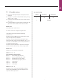
4. Product overview
4.1 Versions
The following options are available for delivery:
− ES module:
Evaluation module for draw-in protection light barrier
− I/O module:
Module for input and output expansion
General safety instructions
Low voltage
− DIN EN 60335-1 (Household and similar electrical
appliances - Safety - Part 1: General requirements)
− DIN EN 60335-2-103 (Household and similar electrical
appliances - Safety - Part 2-103: Particular requirements for
drives for gates, doors and windows)
Committee for Workplaces
(Ausschuss für Arbeitsstätten - ASTA)
− ASR A1.7 (Technical Regulations for workplaces -
Doorsandgates)

4 – MSBUS expansion modules / Rev.B 0.02 MSBUS expansion modules / Rev.B 0.02 – 5
EN
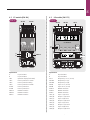
4.2 ES module [EM 184]
XW41B
XW41C
XW41A
LED 4
LED 3
LED 2
LED 1
XP16A XP16B
GN GN
BN BN
WH WH
24V DOWN
E F DIP
12V UP
ON
OFF
XP16A XP16B
XW41A
XW41B XW41C
A
B
4.2 / 1
Explanation:
A Dip switch DIP 1
B Dip switch DIP 2
LED1 Operation display (illuminated)
LED2 Draw-in protection 1 XP16A
LED3 Draw-in protection testing
LED4 Draw-in protection 2 XP16B
XP16A Draw-in protection 1
XP16B Draw-in protection 2
XW41A MSBUS connection
XW41B MSBUS connection
XW41C MSBUS connection
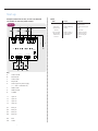
4.3 I/O module [EM 172]
94
1 2 DIP
MSBUS
XW41A
ON
OFF
I1/Q1 I2/Q2 I3/Q3 I4/Q4
92 H1 94 92 H1 H137B 37A 36B 37B
Q3 Q1Q2Q4
I/O MODUL
B5 36
I1 I2 I3 I4
37 B5 31 32
XW41B XW41C
A B C
D E F
G
H
XB195 XB10A XH13
XW41A
XW41B XB53B XW41CXB53A
A
B
4.3 / 1
Explanation:
A Dip switch DIP 1
B Dip switch DIP 2
XH13 Output relay 11+12 (15+16)
XB195A Output relay 13 (17)
XB195B Output relay 14 (18)
XB53A Input 11+12 (15+16)
XB53B Input 13+14 (17+18)
XW41A MSBUS connection
XW41B MSBUS connection
XW41C MSBUS connection
LED1 (A) Input 11 (15) active
LED2 (B) Output 11 (15) active
LED3 (C) Input 12 (16) active
LED4 (D) Output 12 (16) active
LED5 (E) Input 13 (17) active
LED6(F) Output13(17)active
LED7 (G) Input 14 (18) active
LED8 (H) Output 14 (18) active

6 – MSBUS expansion modules / Rev.B 0.02 MSBUS expansion modules / Rev.B 0.02 – 7
5.1 DIP switch 1 setting
ATTENTION!
Incorrect selection of the voltage results in destruction of
the light barrier.
Setting Function
OFF Draw-in protection 12V
(Factorysetting)
ON Draw-in protection 24V
5.2 DIP switch 2 setting
Setting Function
OFF both draw-in protection devices act in the
OPEN direction
ON both draw-in protection devices act in the
CLOSED direction
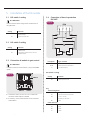
5.3 Connection of module to gate control
ATTENTION!
In order to ensure the correct function, only use the MSBUS
system.
XW41B
XW41C
XW41A
LED 4
LED 3
LED 2
LED 1
XP16A XP16B
GN GN
BN BN
WH WH
24V DOWN
E F DIP
12V UP
ON
OFF
5.3 / 1
XW41A
XW41B XW41C
☞ Connect the control CS 255 / CS 310 / CS 500 to the
connection socket XW41A or XW41B.
☞ If necessary, connect further modules to the connection
socket XW41C.
5.4 Connection of draw-in protection
PNPMFZ
5.4 / 1
Description Type / function
BP30A Draw-in protection, receiver RX
BP30B Draw-in protection, transmitter TX
X1 Connection terminal
DIP switch 1 setting
Setting Function
ON Draw-in protection 24V
Key
Terminal assignment
I –> Test signal for the draw-in protection
GN Signal from the draw-in protection
BN + 24V / +12V DC,
depending on dip switch 1
WH GND
Cable colour key
BN brown
GN green
WH white
YE yellow
5. Installation of the ES module

6 – MSBUS expansion modules / Rev.B 0.02 MSBUS expansion modules / Rev.B 0.02 – 7
EN
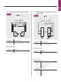
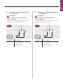
5.5 Connection of draw-in protection OSE
5.5 / 1
Description Type / function
BP29A Draw-in protection, receiver RX
BP29B Draw-in protection, transmitter TX
DIP switch 1 setting
Setting Function
OFF Draw-in protection 12V
5.6 Connection of draw-in protection with
relay output
5.6 / 1
Description Type / function
BP31A Draw-in protection, receiver RX
BP31B Draw-in protection, transmitter TX
DIP switch 1 setting
Setting Function
ON Draw-in protection 24V
Key (5.5 – 5.6)
Terminal assignment
I –> GND transmitter (test line)
GN Signal from the draw-in protection
BN + 24V / +12V DC,
depending on dip switch 1
WH GND receiver
Cable colour key
BN brown
GN green
WH white
YE yellow

8 – MSBUS expansion modules / Rev.B 0.02 MSBUS expansion modules / Rev.B 0.02 – 9
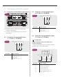
6.1 Connection of I/O module to gate control
94
1 2 DIP
MSBUS
XW41A
ON
OFF
I1/Q1 I2/Q2 I3/Q3 I4/Q4
92 H1 94 92 H1 H137B 37A 36B 37B
Q3 Q1Q2Q4
I/O MODUL
B5 36
I1 I2 I3 I4
37 B5 31 32
XW41B XW41C
A B C
D E F
G
H
XW41B XW41C
XW41A
6.1 / 1
☞ Connect the control CS 255 / CS310 / CS500 to the
connection socket XW41A.
☞ If necessary, connect further modules to the connection
socket XW41B.
6.2 Connection of programmable input
11/15 and 12 / 16 (XB53A)
- XB53A
B5 36 37
I1
I2
6.2 / 1
Description Type / function
I1 Button / switch
programmable input 11 / 15
I2 Button / switch
programmable input 12 / 16
6.3 Connection of programmable input
13/17 and 14 / 18 (XB53B)
-XB53B
B5 3231
I3 I4
6.3 / 1
Description Type / function
I3 Button / switch
programmable input 13 / 17
I4 Button / switch
programmable input 14 / 18
6.4 Connection of programmable output
11/15 and 12 / 16 (XH13)
ATTENTION!
Danger of damage to the circuit board due to
incorrect connection!
In order to avoid damage to the circuit boards, the contact
load (max. 230 V / 4 A) must be observed.
-XH13
L/+
N/-
Q1
-P1
H1 36A 36B 37A 37B
Q2
-P2
6.4 / 1
Description Type / function
P1 Consumers (e.g.: signal lamp)
P2 Consumers (e.g.: signal lamp)
L / + Customer’s power supply
N / – Customer’s power supply
Q1 Relay, programmable output 11 / 15
Q2 Relay, programmable output 12 / 16
6. Installation of the I/O module

8 – MSBUS expansion modules / Rev.B 0.02 MSBUS expansion modules / Rev.B 0.02 – 9
EN
6.5 Connection of programmable output
13/17 (XH19A)
ATTENTION!
Danger of damage to the circuit board due to
incorrect connection!
In order to avoid damage to the circuit boards, the contact
load (max. 230 V / 4 A) must be observed.
-XH19A
L/+
N/-
-P1
H1 92 94
Q3
92
94
H1
6.5 / 1
Description Type / function
P1 Consumers (e.g.: signal lamp)
L / + Customer’s power supply
N / – Customer’s power supply
Q3 Relay, programmable output 13 / 17
6.6 Connection of programmable output
14/18 (XH19B)
ATTENTION!
Danger of damage to the circuit board due to
incorrect connection!
In order to avoid damage to the circuit boards, the contact
load (max. 230 V / 6 A) must be observed.
-XH19B
H1 92 94
Q4
L/+
N/-
-P1
92
94
H1
6.6 / 1
Description Type / function
P1 Consumers (e.g.: signal lamp)
L / + Customer’s power supply
N / – Customer’s power supply
Q4 Relay, programmable output 14 / 18

10 – MSBUS expansion modules / Rev.B 0.02 MSBUS expansion modules / Rev.B 0.02 – 11
7. Start-up
7.1 Start-up of the ES module
WARNING!
Risk of injury due to electric shock!
Contact with mains voltage results in a danger of electric
shock.
☞ Before performing wiring work, always disconnect the
drive system from the power supply.
☞ Make sure that the power supply remains disconnected
during wiring work.
☞ Connect 1 or 2 roll-up protection systems to the inputs
XP16A and/or XP16B of the ES module in a de-energised
state.
☞ Depending on the type, use DIP 1 to select the supply
voltage 12 or 24VDC (factory setting 12V).
☞ Use DIP 2 to select the desired monitoring direction (factory
setting: Monitoring when driving up).
☞ Connect the enclosed BUS cable with the module and the
gate control.
☞ If multiple modules are used, connect one module with the
gate control and the further modules with each other.
☞ Switch on the mains voltage to the gate control.
The module now start the automatic addressing and detection
oftheconnectedsystems(chaseLED1-4).
After successful teach-in, LED1 (green) and the LED for the
active roll-up protection (LED 2 and/or 3) light up.
Please note:
If only 1 roll-up protection system is connected to the ES
module, the unused input will be automatically deactivated
during addressing. This means that the function is also
guaranteed with a single roll-up protection system. An
incorrectly connected or defective system will not be detected
and the corresponding input will also be deactivated.
If a further roll-up protection system is connected at a later
time, renewed addressing of the BUS system must take place
after the system has been connected. This takes place via the
parameter “Reset MS BUS” in the input menu of the door
controls CS310 and CS255.
REFERENCE
Forfurtherinformationrefertotheinstructionsforthe
respective door control.
Please note:
A maximum of 1 ES module can be used for each running
direction (OPEN and CLOSE). 2 modules for the same
direction of travel are not supported!
Faults
Fault Cause Solution
AllLEDsashing. Bus cable interrupted. Check connections.
Replace cable.
LEDs go on
and off in turn
(chase).
MSBUS addressing
running.
Wait until chase goes
out.
Max. 2 min.
Despite
interruption of
the draw-in light
barrier gate does
not stop.
System not detected.
Incorrect connection.
Incorrect DIP switch
setting.
Check DIP switch
setting.
Check connections.
Perform MSBUS reset
on the gate control.

10 – MSBUS expansion modules / Rev.B 0.02 MSBUS expansion modules / Rev.B 0.02 – 11
EN
7.2 I/O module start-up
☞ Fullyconnecttherequiredinputsandoutputswhilstde-
energised.
☞ Using DIP 1+2, select the desired address (factory setting:
address1DIP1+2OFF).
☞ Connect the enclosed BUS cable with the module and the
gate control.
☞ If multiple modules are used, connect one module with the
gate control and the further modules with each other.
Please note:
Each address may only be used 1x!
☞ Switch on the mains voltage to the gate control.
The modules now start the automatic addressing
(chaseLED1-8).
Followingsuccessfuladdressing,onlytheLEDsoftheactive
inputs or outputs are still illuminated.
If address 1 has been selected (factory setting), the input
menu for the gate control shows the additional relays 11-14
orinputs11-14.Withaddress1,thetwo-waytrafcfunction
is automatically pre-assigned.
If address 2 has been selected, the input menu for the gate
control shows the additional relays 15-18 or inputs 15-18.
Please note:
Addresses 3+4 are presently not supported!
Address 1 = 11 - 14
(Pre-setting for two-way trafc)
Relay11= MOD1trafclightred,inside
Relay12= MOD23trafclightgreen,inside
Relay13= MOD60trafclightred,outside
Relay14= MOD62trafclightgreen,outside
Input 11= Open outside
Input 12= Open inside
Input 13 = Close button
Address 2 = 15 - 18
If address 2 is set, all relays are deactivated according to
factorysettings(MOD28)andmustbeconguredviathe
input menu for the gate control.
DIP switch setting
Address DIP switch 1 DIP switch 2
1 OFF OFF
2 OFF ON
3 not available
4 not available

12 – MSBUS expansion modules / Rev.B 0.02 MSBUS expansion modules / Rev.B 0.02 – 13
Example connection CS 255 / CS 310 / CS 500 with
I/O module for two-way trafc control
X1
X2
X1
X2
X1
X2
X1
X2
CBA D
13
14
13
14
13
14
+ / L
- / N
XW41C
LED
GN
GN
GN
GN
RD
RD
RD
RD
Q2Q3Q4
Q1
I1 I2 I2
94 92 H1 94 92 H1 37B 37A 36B 36A H1
B5 36 37 B5 31 32
-P
I4
E
F G H
7.2 / 1
Key
A Green outside
B Red outside
C Green inside
D Red inside
E Trafclightsforpowersupply
(+ / - 24V or L/N 230V AC)
F OPENinside
G OPEN outside
H CLOSED
I1 Input 11
I2 Input 12
I3 Input 13
I4 Input 14
Q1 Relay 11
Q2 Relay 12
Q3 Relay 13
Q4 Relay 14
RD Red
GN Green
Faults
Fault Cause Solution
AllLEDsashing. Bus cable interrupted. Check connections.
Replace cable.
LEDs go on
and off in turn
(chase).
MSBUS addressing
running.
Wait until chase goes
out.
Max. 2 min.
Input or output
does not react
with desired
function.
Mode for input or
output incorrectly
parametrised.
Check the function
mode in the input
menu for the gate
control.
Start-up

12 – MSBUS expansion modules / Rev.B 0.02 MSBUS expansion modules / Rev.B 0.02 – 13
EN
8. Technical data
8.1 Technical data for the ES module
Operating voltage: 24 V DC
Protection grade: IP 20
Cabling: conventional | MSBUS cable
Dimensions (WxHxD): 45 mm x 125 mm x 50 mm
Internal consumption: max. 100 mA
Weight: 0.25 kg
8.2 Technical data for the I/O module
Operating voltage: 24 V DC
max. contact load
relay outputs:
230 V / 4 A
Protection grade: IP 20
Cabling: conventional | MSBUS cable
Dimensions (WxHxD): 85 mm x 125 mm x 50 mm
Internal consumption: max. 100 mA
Weight: 0.25 kg

14 – MSBUS expansion modules / Rev.B 0.02 MSBUS expansion modules / Rev.B 0.02 – 15
9. Maintenance
The expansion module is maintenance-free.
WARNING!
Life-threatening danger due to electric shock!
☞ The control MUST be disconnected from the power
supply before carrying out any maintenance work on the
control unit or door system. Take measures to ensure that
the power supply remains disconnected for the duration
of the work.
The following points must be taken into account when
carrying out maintenance on the door system:
− Maintenance must only be carried out by authorised
persons.
− Directive ASR A1.7 must be complied with.
− Worn or faulty parts must be replaced.
− Only approved parts may be installed.
− All maintenance work must be documented.
− Replaced faulty parts must be disposed of properly in
accordance with the materials they contain and local
regulations.

14 – MSBUS expansion modules / Rev.B 0.02 MSBUS expansion modules / Rev.B 0.02 – 15
EN
10. Manufacturer‘s Declaration
MFZAntriebeGmbH&Co.KG
Neue Mühle 4
D - 48739 Legden
Declaration of incorporation
within the context of Machinery Directive 2006/42/EC
for incorporation in an incomplete machine according to
Appendix II, Part 1B
Declaration of conformity
in accordance with the directives:
− Electromagnetic compatibility 2014/30/EU
− RoHs 2011/65/EU + RoHs 2015/863/EU +
RoHs 2017/2102/EU
We hereby declare that the following listed product
Product designation: Expansion module
Type designation: MS BUS Module
asanincompletemachinespeciedexclusivelyforintegration
with a door system and designed, constructed, and produced
in conjunction with the following directives:
− Machinery Directive 2006/42/EC
− Electromagnetic Compatibility Directive 2014/30/EU
− RoHS Directive 2011/65/EU + RoHs Directive 2015/863/EU
+ RoHs Directive 2017/2102/EU
Furthermore,therequirementsoftheLow-VoltageDirective
2014/35/EU are met according to Appendix I Part 1.5.1
of the Machinery Directive 2006/42/EC.
Applied and consulted standards:
EN 12453 Doors - Safety in use of power operated
doors: Requirements and test methods
EN 12978 Industrial, commercial and garage doors
and gates - Safety devices for power
operated doors and gates: Requirements
and test methods
EN ISO 13849-1 Safety of machinery - Safety-related parts of
control systems - Part 1: General principles
for design
EN 60335-1 Household and similar electrical appliances
- Safety - Part 1: General requirements
EN 60335-2-103 Household and similar electrical appliances -
Safety - Part 2-103: Particular requirements
for drives for gates, doors and windows
EN 61000-6-2 Electromagnetic compatibility (EMC) —
Part 6-2: Generic standards - Immunity
standard for industrial environments
EN 61000-6-3 Electromagnetic compatibility (EMC) —
Part 6-3: Generic standards - Emission
standard for residential, commercial and
light-industrial environments
The special technical documents were created according to
Appendix VII Part B of the Machinery Directive (2006/42/EC).
We are obligated to transmit these to market monitoring
agenciesinatimelymanneruponjustiedrequestin
electronic form.
Authorised representative for compiling the technical
documents:
MFZAntriebeGmbH&Co.KG-NeueMühle4-
48739 Legden - Germany
Incomplete machines within the context of EC Directive
2006/42/ECarethereforeonlyspeciedforincorporation
with other machines or with other incomplete machines or
systems or combined with them to form a machine within
thecontactofthedirectiveindicatedabove.Forthisreason,
this product may only be commissioned once it has been
determined that the complete machine /system into which
it has been incorporated corresponds with the indicated EC
guidelines.
Incaseofchangestotheproductthatarenotconrmedby
us, this declaration is void.
Legden, dated 01.05.2020
Dirk Wesseling, General Manager

#1700026952
#160915
-
 1
1
-
 2
2
-
 3
3
-
 4
4
-
 5
5
-
 6
6
-
 7
7
-
 8
8
-
 9
9
-
 10
10
-
 11
11
-
 12
12
-
 13
13
-
 14
14
-
 15
15
-
 16
16


Marantec EM 172 Owner's manual
- Type
- Owner's manual
- This manual is also suitable for
Ask a question and I''ll find the answer in the document
Finding information in a document is now easier with AI
Related papers
-
Marantec EM 172 Owner's manual
-
-
-
-
-
Marantec CS 300 Owner's manual
-
-
Marantec Comfort 390 plus Owner's manual
-
-
Marantec CS 320 Owner's manual
Other documents
-
Ergotron T-Slot Bracket User guide
-
Mitsubishi Electric MFZ-KJ35VE User manual
-
Aaeon PCM-3660 Rev.B User manual
-
-
Mitsubishi MFZ-KJ12NA-U1 Product information
-
Grisham 90002 Measurement Guide
-
-
Chief MFMUS Installation guide
-
-
Vivanco 28270 User manual