Page is loading ...

CONGRATULATIONS!
YOU HAVE PURCHASED THE WORLDS FINEST
MIG WELDING SYSTEM A V AILABLE EXCLUSIVEL Y FROM
SNAP-ON TOOLS. THE SNAP-ON MUSCLE MIG
SYSTEM MODEL# MM350XL IS DESIGNED AND
ENGINEERED BY THE PROS FOR THE PROS.
UNDER NORMAL CARE THIS SYSTEM WILL PROVIDE
YOU WITH YEARS OF UNSURPASSED SERVICE
AND MOST IMPORTANTLY PERFORMANCE.
OWNER'S MANUAL
FOR TECH. SERVICE, CALL TOLL-FREE 1-800-232-9353.
PROVIDE MODEL & SERIAL NUMBER.
INSTALLATION
OPERATION
MAINTENANCE
MM350XL M.I.G. COMBINATION UNIT

2
WARNING
• Materials can cause sparks or flying metal
when heated which can cause fire.
Wear safety shield and protective cloth-
ing (user and bystanders).
Sparks, fire and flying metal can cause in-
jury.
WARNING
• Electrical shock can result from absence
of grounding prong.
Do not remove or bypass the grounding
prong in any electrical plug.
Electrical shock can cause injury.
WARNING
• Smoke, fumes and gases are created by
the welding process.
Use only in well ventilated area.
Avoid breathing smoke, fumes and
gases.
Smoke, fumes and gases can cause injury.
DANGER
• Electric welding causes ultraviolet rays
and weld spatter.
Bystanders will be exposed to ultra-
violet rays and weld spatter.
Wear welding helmet with appropriate
shade lens while using electric welders.
Do not allow bystanders while welding.
Wear safety shield and protective cloth-
ing (user and bystanders).
Read and follow instructions.
Ultraviolet rays will burn eyes; weld
spatter can cause injury.
WARNING
• Welded surface can be hot and cause
burns and injury.
SAFETY - WELDERS SAFETY - WELDERS

3
MANUFACTURER’S LIMITED WARRANTY
This equipment is warranted against defects in materials and workmanship for a period of two years from the
date of purchase.
EXCEPTION: THE MIG TORCH IS WARRANTED FOR A PERIOD OF 30 DAYS FROM THE DATE OF
PURCHASE.
Should the equipment become defective for such reason, the Manufacturer will repair it without charge, if it
is returned to the Manufacturer’s factory, freight prepaid. This warranty does not cover: (1) failure due to normal
wear and tear; (2) consumable parts, such as, but not limited to, torch contact tips, gas cups and insulating
bushings; (3) damage by accident, force majeure, improper use, neglect, unauthorized repair or alteration; (4)
anyone other than the original purchaser.
THIS LIMITED WARRANTY IS IN LIEU OF ALL OTHER WARRANTIES, EXPRESS OR IMPLIED. THE
MANUFACTURER SHALL NOT BE LIABLE FOR ANY INJURY TO PERSONS, INCLUDING DEATH; OR LOSS
OR DAMAGE TO ANY PROPERTY, DIRECT OR CONSEQUENTIAL, INCLUDING, BUT NOT LIMITED TO,
LOSS OF USE, ARISING OUT OF THE USE, OR THE INABILITY TO USE, THE PRODUCT. THE USER
ASSUMES ALL RISK AND LIABILITY WHATSOEVER IN CONNECTION WITH THE USE OF THE PRODUCT,
AND BEFORE DOING SO, SHALL DETERMINE ITS SUITABILITY FOR HIS INTENDED USE, AND SHALL
ASCERTAIN THE PROPER METHOD OF USING IT.
SOME STATES DO NOT ALLOW LIMITATIONS ON HOW LONG AN IMPLIED WARRANTY LASTS, OR
THE EXCLUSIONS OR LIMITATIONS OF INCIDENTAL OR CONSEQUENTIAL DAMAGES. SO THE ABOVE
LIMITATIONS OR EXCLUSIONS MAY NOT APPLY TO YOU. THIS WARRANTY GIVES YOU SPECIFIC
LEGAL RIGHTS, AND YOU MAY HAVE OTHER RIGHTS WHICH MAY VARY FROM STATE TO STATE.
TABLE OF CONTENTS
SAFETY PRECAUTIONS ............................................................. 2
INTRODUCTION ........................................................................... 4
DESCRIPTION, SPECIFICATIONS .............................................. 5
CHECK LIST (CONTENTS) .......................................................... 6
INSTALLATION & ELECTRICAL REQUIREMENTS ................... 7
OPERATION ............................................................................... 12
WELDING .................................................................................... 14
MAINTENANCE ........................................................................... 16
TROUBLE SHOOTING CHART.................................................. 18
WIRE FEED CALIBRATION ....................................................... 22
CONNECTING FLEXTIG OR SPOOL GUN ............................... 23
LINER INSTALLATION ............................................................... 24
PARTS BREAKDOWN - MIG TORCH ........................................ 25
PARAMETER CHART ................................................................. 25
OPTIONS - FLEXTIG OR SPOOL GUN ..................................... 27

4
INTRODUCTION
The Snap-on Tools MM350XL is a
combination welding power source,
remote feed unit, MIG torch and
accessory package, which is de-
signed to meet the requirements of
the light to heavy metal fabrica-
tion industries. The MM350XL pro-
duces fusion welds by the Gas Metal
Arc Welding process (GMAW or MIG),
on steel and aluminum up to "1/2"
thick, using .023" through 1/16"
steel wire and .023" through 3/64"
aluminum wire with the optional
MHG5-B spool gun. (optional liners
and drive rolls must be purchased to
cover all given wire types and
sizes). Heavier sections can be
easily welded using slightly dif-
ferent techniques.
The number of controls on the unit
have been reduced to assist inexpe-
rienced operators to learn MIG
welding. This facilitates rapid
set up for welding various thick-
nesses of material requiring vari-
ous heat inputs. The VOLTAGE
control adjusts the welding voltage
and the WIRE FEED control adjusts
the speed of the wire feed motor.
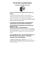
THE MIG PROCESS
AS APPLIED TO THE MM350XL
The MIG process uses a bare,
consumable electrode in the form of
spooled wire, which is fed by a
controllable speed feed unit
through the cable and torch to the
weld. The emerging wire and the
weld are shielded by a stream of
CO2, Argon, or a mixture of the two,
which prevents oxidation of the
molten weld puddle. The gas shield
enables high quality welds to be
made without the use of flux,
eliminating the need for slag or
flux removal after the weld is
completed.
POWER SOURCE
WIRE SPOOL
FEED
ROLLS
WORK
MIG
TORCH
+
REVERSE
POLARITY
(STD.)
_
SHIELDING GAS
The consumable electrode wire is
melted and transferred to the weld
puddle by any of three arc modes;
short arc transfer, globular trans-
fer, or spray arc transfer. The
MM350XL is capable of performing
all modes.
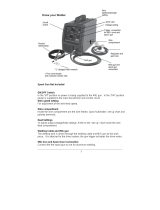
SHORT ARC OR DIP TRANSFER
Short arc transfer occurs at 12 to
22 arc volts (voltage while weld-
ing), depending on wire size. Weld-
ing commences as the arc is struck
and a weld pool is formed. The tip
of the electrode wire dips into the
pool and causes a short circuit.
The short circuit current flow
causes a rapid temperature rise in
the electrode wire and the end of
the wire is melted off. An arc is
immediately formed between the tip
of the wire and the weld pool,
maintaining the electrical circuit
and producing sufficient heat to
keep the weld pool fluid. The
electrode continues to feed and
again dips into the pool.
FIG. 1. SCHEMATIC OF M.I.G. PROCESS
FIG. 2. SHORT ARC TRANSFER
ELEC-
TRODE
WORK

5
SHORT ARC OR DIP TRANSFER (Cont.)
This sequence of events is re-
peated up to 200 times per second.
Short arc transfer is suitable for
positional welding. The heat input
to the workpiece is kept to a
minimum which limits distortion and
makes possible the welding of thin
sheet material.
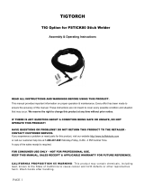
GLOBULAR TRANSFER
Globular transfer occurs at the
intermediate range of 22 to 24 arc
volts, depending on wire size. As
the name implies, the transfer
takes place in the form of irregu-
larly shaped globules. Globular
transfer is useful in cases where a
lower heat input than that of true
spray is required.
DESCRIPTION
The MM350XL consists of a combi-
nation MIG welding power source and
remote feed unit, a MIG torch with
twelve foot cable, a fifteen foot
feeder control cable, a twenty-five
foot work cable with clamp, a twenty
foot power input cable, a gas
regulator - flowmeter, a torch
accessory kit, built-in storage
compartment and a dual cylinder
rack and industrial wheel kit.
Welder controls are simple and
clearly marked. The output voltage
is controlled by a twelve position
tap switch, providing 4 TIG and 8
MIG voltage selections. Wire feed
speed is controlled by the wire
speed potentiometer on the front of
the feed unit.
SPECIFICATIONS
PART NUMBER: MM350XL
INPUT POWER REQUIREMENTS:
Voltage 208/230
Phase single phase
Frequency 50/60 hertz
Current 46/42
DUTY CYCLE - OUTPUT POWER:
@ 100% - 300 Amps
@ 60% - 350 Amps
DUTY CYCLE TIME PERIOD:
10 minutes
OPEN CIRCUIT VOLTAGE:
18 - 42 volts DC
ARC VOLTAGE: 12 - 32 volts DC
WELD CURRENT RANGE:
30 - 350 amps
REMOTE FEED UNIT
Input Voltage 28 VAC
Wire Feed Speed Range: 50-800 IPM
SPRAY TRANSFER
Spray transfer occurs at 22 to 32
arc volts, depending on wire size.
The length of the arc is held
constant by the voltage available.
The higher voltage and current
causes the electrode wire to melt
off before touching the workpiece.
The molten metal crosses the gap to
the workpiece in a spray form.
Spray transfer is used in the down-
hand position and provides higher
deposition rates than short arc
transfer or globular transfer.
ELECTRODE GAS NOZZLE
SHIELDING GAS
WORK
FIG. 3. GLOBULAR TRANSFER
ELECTRODE GAS NOZZLE
SHIELDING GAS
WORK
FIG. 4. SPRAY TRANSFER
(continued on following page)

6
SPECIFICATIONS (Cont.)
CHECK LIST
THE SNAP-ON TOOLS MM350XL INCLUDES
THE FOLLOWING:
1- Combination Power Source/Remote
Feed Unit.
1- Dual Cylinder Rack & Industrial
Wheel Kit.
1- FCA-15X 15 foot Feeder Control
Cable assy.
1- 35XL12 12 foot MIG Torch with
adjustable nozzle.
1- 20CP-3M 20 foot Power Input
Cable.
1- SN-178X521 25 foot Work Cable
and 500 amp clamp.
1- 350LPK Parts Kit.
1- GR-FM Gas Regulator/Flowmeter.
1- ER70S-6-35-3, Sample Spool of
.035 Steel Wire.
1- 8IN-A 8 inch Reel Adapter.
ITEMS REQUIRED FOR MIG WELDING
WHICH ARE NOT PROVIDED WITH THE
MM350XL
1. Full cover welding helmet with
proper colored lens (shade 9 to
11 depending on operator’s pref-
erence).
2. Proper shielding gas and cylin-
der.
3. Leather welding gloves.
4. Electrical power and matching
electrical plug.
THE MM350XL REQUIRES A 208
OR 230 VOLT, SINGLE PHASE,
AC, 60 AMP CIRCUIT
5. Other personal protective
equipment which may vary to
match the welding being per-
formed.
WIRE TYPES: mild steel,
stainless steel, aluminum,
bronze, flux cored,
flux cored - gasless
Recommended (for steel) ER70S-
6
WIRE SIZES: .023" - 1/16" steel,
3/64 - 1/16" aluminum,
(.023" - 3/64" alum. w/spool gun)
.030" - .035" bronze,
.035" - .045" flux cored
(gas shielded or gasless)
Recommended Size:Aluminum .035
Others .035
SHIELDING GASES:
For Steel CO2 or Argon/CO2 mix
Recommended (for steel) 75% Argon/
25% CO2
For Aluminum, Bronze 100% Argon
For Stainless Steel
98% Argon/2% Oxygen
For Flux cored CO2 or
Argon/CO2 mix
DIMENSIONS:
Height 35-3/4 in.(90.8 cm.)
Width 27-1/4 in.(69.2 cm.)
Depth 34-1/2 in.(87.7 cm.)
Weight 275 lbs.(124.9 kg.)
TORCH SPECIFICATIONS
NECK ANGLE: 60 degrees
LEAD LENGTH: 12 feet
OVERALL LENGTH: 12 feet
COOLING METHOD: gas (air)
RATING - DUTY CYCLE:
With Argon/CO2 gas 250 amps @ 100%
With CO2 gas 300 amps @ 100%

7
INSTALLATION
POSITIONING THE UNIT
Locate the unit adjacent to the
welding area and position it so
there is adequate clearance all
around for ventilation and mainte-
nance.
2. Locate the contactor switch,
which is mounted on top of the
main power transformer(See Fig-
ure 5).
CAUTION
MAKE SURE POWER SOURCE IS
UNPLUGGED BEFORE MAKING IN-
PUT SELECTION CHANGE-OVER.
3. Attached to the power source’s
contactor are two (2) two posi-
tion plugs which allows easy
selection of input voltages of
either 208 or 230 volts.
4. Remove both plugs labeled 230V
and connect the two (2) plugs
labeled 208V.
5. Reattach the left side panel of
the machine. Voltage input se-
lection is now complete.
ELECTRICAL SUPPLY
FIG. 5. INPUT VOLTAGE SELECTIONS
CONTACTOR SWITCH
CONNECT
"230" WIRE FOR
OPERATION ON
230 VOLT INPUT.
CONNECT "208"
WIRE FOR
OPERATION ON
208 VOLT INPUT
FRONT OF
MACHINE
WARNING
• Electrical shock can result from absence
of grounding prong.
Do not remove or bypass the grounding
prong in any electrical plug.
Electrical shock can cause injury.
(continued on following page)
WARNING
• Smoke, fumes and gases are created by
the welding process.
Use only in well ventilated area.
Avoid breathing smoke, fumes and
gases.
Smoke, fumes and gases can cause injury.
Ensure that there is a 208 or 230
volt, single phase, 60 amp electrical
supply within easy reach of the
unit. The input cable supplied is 20
feet long.Attach a suitable plug
making sure the green wire is attached to
the ground terminal of the wall plug. All
wiring should be performed by a
qualified electrician.
230V INPUT SELECTION
1. Factory selected no change is
needed.
208V INPUT SELECTION
1. Remove the left side panel.

8
INSTALLING THE FEEDER CONTROL CABLE
ASSEMBLY
1. Uncoil the cable assembly.
3. With the proper size wrench
attach the gas fitting to the gas
terminal (located on the front
of the feed unit).
4. Connect the control plug (female
pins)onto the control recep-
tacle (INPUT) and tighten (lo-
cated on the front of the feed
unit).
5. Plug the power plug into the
positive (+) terminal(located
on the front of the welding
machine).
6. Connect the control plug (male
pins) onto the control recep-
tacle (OUTPUT)and tighten (lo-
cated on the front of the welding
machine).
SHIELDING GAS CONNECTIONS
1. Place a cylinder of the appro-
priate shielding gas in the rack
at the rear of the machine and
secure it with the chain pro-
vided.
FIG. 6. FCA-15X FEEDER CABLE ASSEMBLY
GAS
FITTING
CONTROL
PLUG
(FEMALE
PINS)
CURRENT
LUG
CONTROL
PLUG
(MALE
PINS)
POWER
PLUG
CURRENT
CABLE
FEED
CABLE
ASSEMBLY
GAS HOSE
2. Insert the current lug through
the hole on the front of the feed
unit and with the proper size
wrench fasten it to the input
current stud, located on the
back side of the drive bracket.
CONTROL
CABLE
FIG. 7. CABLE CONNECTION TO FEED UNIT
FEED
UNIT
TO GAS
TERMINAL
TO CURRENT
STUD
INPUT
CURRENT
STUD
CABLE
HOLE
DRIVE
BRACKET
TO
CONTROL
RECEP-
TACLE
(INPUT)
FIG. 8. CABLE CONNECTION TO
WELDING MACHINE
WELDING
MACHINE
TO CONTROL
RECEPTACLE
(OUTPUT)
TO (+)
TERMINAL
(STANDARD)

9
2. Rapidly open and close the cyl-
inder valve. This will purge
dust and foreign matter from the
valve.
CAUTION
Take care to point the
valve outlet away from
yourself or other people,
as escaping high pressure
gas may be dangerous.
4. Fit the gas hose from the welding
machine to the regulator outlet
fitting and tighten it with a
wrench. Open the cylinder valve.
When welding steel, the gas flow
rate is 30 CFH.
NOTE
The MM350XL must be turned
"ON" and the MIG torch
trigger depressed, before
the gas flow rate can be
adjusted.
TORCH CONNECTION
1. Open the access door of the Feed
unit to its fullest extent.
NOTE
Prior to inserting the MIG
torch into the torch panel
mount, apply anti-spatter
spray to the "O" rings.
2. Back out the thumb screw located
on the drive bracket inside the
machine. Insert the MIG torch
into the torch panel mount and
TIGHTEN THE THUMB SCREW SE-
CURELY.
WARNING
SEVERE DAMAGE TO THIS
PRODUCT MAY RESULT.
TIGHTEN THUMB SCREW BE-
FORE EACH USE.
FIG. 9. GAS FLOW ADJUSTMENT
GAUGE -
INDICATES
TANK
PRESSURE
OUTLET
FITTING
TO
WELDING
MACHINE
GAS FLOW
ADJUSTING
KNOB
INLET
FITTING
TO
TANK
FLOW TUBE
INDICATES
FLOW RATE
IN C.F.H.
3. Attach the gas regulator - flow-
meter supplied with this unit,
to the cylinder valve using a
suitable wrench.
NOTE
If this unit is to be used
with 100% CO2 shielding
gas, an optional gas regu-
lator coupler is required.
FIG. 10. TORCH CONNECTION
DRIVE
ROLL
TORCH
PANEL
MOUNT
THUMB
SCREW
PRESSURE
ROLL
INLET
GUIDE
MIG
TORCH
DRIVE
BRACKET
"O"
RINGS

10
FITTING AND THREADING THE ELEC-
TRODE WIRE - ALWAYS USE ER70S-6
WELDING WIRE WHEN WELDING STEEL.
1. Remove the wire spool clip from
the spool hub.
2. Unpack the spool of welding wire
from its protective packaging.
3. Place the spool of ER70S-6 weld-
ing wire onto the hub. The wire
is fed off the bottom of the
spool.
CAUTION
Look for wire protruding
from the center of the
spool. The protruding wire
is electrically HOT during
welding and must not touch
the machine.
6. Make sure the double v-groove
drive roll is installed to match
the wire size. To change the
wire size setting, remove the
drive roll, turn it over and
reinstall it on the shaft.
FIG. 11. FITTING AND THREADING THE ELECTRODE
DRIVE
ROLL
ELECTRODE
(MIG WIRE)
SPOOL
CLIP
PRESSURE
ROLL ARM
SPOOL
HUB
4. Replace the spool clip on the
hub.
5. Unlatch the pressure roll arm
and swing it open.
FIG. 12. DOUBLE GROOVE DRIVE ROLL
"B" SIDE FACING IN FOR
.030" - .035" STEEL WIRES
"C" SIDE FACING IN FOR
.040" - .045" STEEL WIRES
7. Release the wire from the spool
and trim off the kinked end with
wire cutters. The wire must be
straight when it enters the
inlet guide.
8. Thread the electrode wire
through the inlet guide, over
the feed roll and into the liner.
Ensure that the wire locates in
the feed roll groove. Do not
allow the wire on the spool to
loosen.
9. Close and relatch the pressure
roll arm.
10.Stretch the torch cable straight
out in front of the machine
making sure there are no kinks.
Remove the nozzle and contact
tip from the torch.
INLET
GUIDES

11
11.Turn on the circuit breaker on
the front of the machine. The
cooling fan will start and the
"ON" indicator light will illu-
minate. Set the MIG/TIG VOLTAGE
control switch to "MIG 3" and the
WIRE SPEED control to "5". Pull
the trigger on the MIG torch.
The wire feed system will start
and wire will be fed through the
cable liner and torch. If the
wire does not feed, or appears to
slip, tighten the pressure roll
arm adjusting nut. Feed the wire
until it protrudes from the
front of the torch approximately
six inches.
CAUTION
Keep hands and face away
from the front of the torch
and do not allow the wire to
contact ground. The wire
is electrically HOT when
the torch trigger is actu-
ated.
12.Install the contact tip over the
protruding wire and tighten it
firmly using a proper size
wrench. Make sure the tip is the
correct size for the wire being
used.
13.Install the nozzle on the torch.
For steel, the contact tip
should be flush or stick out up
to 1/16 inch beyond the end of
the nozzle. Using wire cutters,
trim off the wire so the stickout
is approximately 1/4 inch for
steel.
14.For steel welding only, spray
anti-spatter compound inside
the nozzle and on the outside of
the contact tip.
WIRE FEED PRESSURE ROLL ADJUST-
MENT
The wire feed pressure roll is
adjusted at the factory, prior to
delivery. It may be necessary to
readjust the setting as components
"seat in" or when changing to a
different diameter wire. To check
for proper roll pressure, hold the
torch in one hand and pinch the wire
between two fingers of the other
gloved hand. Pull the torch trig-
ger. If the wire continues to feed
when firm pressure is applied to the
wire, the pressure roll adjusting
nut should be backed off until the
feed rolls start to slip. If the
wire will not feed with very little
pressure applied, the pressure roll
adjusting nut should be tightened.
FIG. 14. PRESSURE ROLL ADJUSTMENT
PRESSURE
ROLL ARM
PRESSURE ROLL
ADJUSTING NUT
PRESSURE
ROLL
DRIVE
ROLL
(continued on following page)
1/4"
STICK-OUT
FIG. 13. WIRE STICKOUT

12
WIRE SPOOL DRAG ADJUSTMENT
The center bolt of the Spool Hub
Assembly is used for drag adjust-
ment.
1. If there is too much drag,
causing excessive slippage, re-
duce the drag by turning the
center adjustment bolt,
counter-clockwise
.
2. If there is not enough drag,
causing the wire spool to over-
ride and the wire to tangle,
increase the drag by turning the
center adjustment bolt,
clock-
wise
.
OPERATION
The following operating instruc-
tions and detailed setup procedures
enable an operator without previous
experience to produce quality fu-
sion welds. It is recommended that
an operator without prior experi-
ence with this equipment, first
practice on scrap metal of the same
type and thickness as the material
to be welded.
OPERATING SEQUENCE
1. Make sure that the pieces of
metal to be welded are free of
grease, dirt, paint and scale.
Use a wire brush to remove paint
and scale. Paint must be com-
pletely removed to bare metal.
Grease and oil could burn and
cause a fire or safety hazard.
Failure to clean the metal prop-
erly will result in erratic and
porous welds.
2. Install the unit as directed in
the installation instructions
and make sure the work clamp is
firmly attached to a cleaned
area on the workpiece to be
welded.
3. Open the shielding gas cylinder
valve. Press the torch trigger
and listen for gas flow.
CAUTION
The welding wire will feed
when the trigger is actu-
ated. Take care that the
wire is not directed to hit
yourself or anything that
is common to the work cable
on the welder.
FITTING AND THREADING THE ELEC-
TRODE WIRE (Cont.)
FIG. 15. WIRE SPOOL DRAG ADJUSTMENT
CENTER
"ADJUSTMENT"
BOLT
SPOOL HUB
ASSEMBLY
WORK (GROUND) CABLE
Uncoil the work (ground) cable
and plug it into the negative (-)
terminal on the machine.

13
PROCESS SELECTION
The following controls are lo-
cated on the front of the MM350XL.
(continued on following page)
A.
CONTROL
RECEP-
TACLE
(INPUT)
B.
STORAGE
COMPART-
MENT
C.
MIG/TIG
VOLTAGE
SWITCH
D.
VOLT-
METER
E.
CIRCUIT
BREAKER
F.
"ON"
INDICATOR
LIGHT
FIGURE 16. FRONT PANEL
A. CONTROL RECEPTACLE (INPUT)
Input receptacle for wire feed
voltage, trigger circuit and
wire speed control from welding
machine.
B. STORAGE COMPARTMENT
Compartment for tools and the
350LPK parts kit.
C. MIG/TIG VOLTAGE SWITCH
Twelve position switch provides
"4" TIG (requires optional FLEX
TIG) and "8" MIG voltage set-
tings.
D. VOLTMETER
Indicates open circuit voltage
when torch trigger switch is
activated and arc (welding)
voltage during welding.
E. CIRCUIT BREAKER
Primary power switch and over-
load protection device.
F. "ON" INDICATOR LIGHT
Illuminates when the circuit
breaker on the machine is "ON".
G. GAS TERMINAL
Single terminal connection for
gas from welding machine.
H. OCV/GAS PURGE
Operates the gas solenoid to
purge the lines of impurities
prior to welding. Pressing the
switch also causes open circuit
voltage to be registered on the
power source voltmeter.
CAUTION
Torch is electrically HOT
when switch is actuated.
I. WIRE SPEED
Potentiometer controls speed of
wire drive motor to give wire
speed of 50 to 800 inches per
minute.
J. TORCH PANEL MOUNT
Combination current output,
contactor switch connection,
gas supply connection, and wire
feed output in a single unit.
K. CONTROL RECEPTACLE (OUTPUT)
Output receptacle for wire feed
voltage, trigger circuit and
wire speed control out to the
remote feed unit.
L. (+)POSITIVE TERMINAL
Positive output terminal from
the welder DC power source. The
Power plug is inserted into this
terminal for standard welding
operation. The work cable can be
plugged into this terminal for
straight polarity welding on
very light sheet metal, or for
using flux cored gasless wire.
G.
GAS
TERMINAL
H.
OCV/GAS
PURGE
I.
WIRE
SPEED
J.
TORCH
PANEL
MOUNT
K.
CONTROL
RECEPTACLE
(OUTPUT)
L.
(+)POSITIVE
TERMINAL
M.
(-)NEGATIVE
TERMINAL

14
PROCESS SELECTION (cont.)
M. (-)NEGATIVE TERMINAL
Negative output terminal. The
work cable is plugged into this
terminal during standard weld-
ing operation. The Power plug
can be inserted into this termi-
nal for straight polarity weld-
ing on very light sheet metal, or
for using flux cored gasless
wire.
WELDING
Optimum control settings will
vary according to the thickness of
the metal, the type of joint,
operator preference, etc. Best
results can be obtained through
experience with the welding machine
or by making trial welds. Select
some sample material of the same
type and thickness as the material
to be welded. Set the welding
controls(using the parameter chart
located on the door of the feed unit
or on page 25) for optimum results
using the sample material thickness
and wire size being used as a
starting point, weld until experi-
ence is gained using the unit.
CONTINUOUS WELDING ON
STEEL
1. Trim the electrode wire to leave
approximately 1/4 inch stickout
beyond the end of the contact tip
and install the welding nozzle.
The contact tip should be flush
or stick out up to 1/16 inch
beyond the end of the nozzle.
FIG. 17. NOZZLE ADJUSTMENT
FOR WELDING STEEL
NOZZLE
CONTACT TIP
(FLUSH TO
1/16" STICKOUT)
ELECTRODE WIRE
(1/4" STICKOUT)
WARNING
• Materials can cause sparks or flying metal
when heated which can cause fire.
Wear safety shield and protective cloth-
ing (user and bystanders).
Sparks, fire and flying metal can cause in-
jury.
DANGER
• Electric welding causes ultraviolet rays
and weld spatter.
Bystanders will be exposed to ultra-
violet rays and weld spatter.
Wear welding helmet with appropriate
shade lens while using electric welders.
Do not allow bystanders while welding.
Wear safety shield and protective cloth-
ing (user and bystanders).
Read and follow instructions.
Ultraviolet rays will burn eyes; weld
spatter can cause injury.
WARNING
• Welded surface can be hot and cause
burns and injury.

15
2. Spray the inside of the nozzle
and the outside of the contact
tip with anti-spatter compound.
3. Locate the torch over the joint
to be welded with the contact tip
approximately 3/4 inch from the
work surface.
4. Use a welding helmet with a shade
9 to 11 filter lens, depending on
operator preference.
NOTE
When welding steel, the ideal
position for holding the torch
is inclined approximately 30
degrees towards the direction
of travel. This allows the arc
to be seen easily, resulting
in greater control of the weld
pool. Most right-handed wel-
dors move from left to right.
This method, known as forehand
welding, provides a gas shield
for the cooling weld puddle
and helps in obtaining an
oxidation free weld deposit.
FIG. 18. TORCH POSITION FOR WELDING STEEL
- RIGHTHANDED WELDOR
WORK
SHIELDING
GAS
30 DEGREES
DIRECTION
OF TRAVEL
5. Squeeze the torch trigger. The
wire will feed and an arc will be
established. As the weld is
deposited, move the torch slowly
along the weld seam at a constant
speed, while maintaining a con-
stant arc length and a constant
tip-to-work distance.
OPERATING HINTS
BURN BACK
In the event the welding wire
burns back into the contact tip:
1. Remove the nozzle from the
torch.
2. Unscrew the contact tip from the
gas diffuser using a pair of
pliers as the tip will be very
hot.
3. Free the wire from the contact
tip and clean the end of the tip
so the new wire will slide
smoothly through the hole. DO
NOT use a drill or reamer to
clean the hole as they will
enlarge it and cause an erratic
arc. Replace the contact tip if
it is badly damaged.
4. Install the contact tip in the
torch and tighten it firmly with
an appropriate wrench.
5. Reinstall the torch nozzle.
6. If the wire continues to burn
back, check for erratic wire
feed, or speed up the wire by
increasing the WIRE SPEED con-
trol setting or reducing the
VOLTAGE control setting.
(continued on following page)

16
OPERATING HINTS (Cont.)
SPATTER
Before beginning to weld and
periodically during welding, the
torch nozzle must be removed and the
spatter (small globules of melted
metal) cleared from the inside of
the nozzle and the outside of the
contact tip and the gas diffuser.
Spatter buildup between the contact
tip and the nozzle can cause a short
circuit and consequently, failure
of the torch or welding machine.
The frequent use of anti-spatter
spray will help prevent the adher-
ence of spatter to the torch compo-
nents.
NOTE
DO NOT use any anti-spatter
spray when welding stainless
steel.
Restricted gas flow, holding the
torch too far from the work piece,
and the use of CO2 gas rather than
75% Argon - 25% CO2 will increase
the spatter levels.
MAINTENANCE
To ensure that this equipment
maintains its operating effi-
ciency, the following maintenance
schedule and procedures are recom-
mended. These routines should be
performed regularly by the opera-
tor.
REGULARLY - Usage and shop condi-
tions determine frequency.
1. Remove and clean the torch
nozzle and contact tip. The use
of anti-spatter compound will
reduce the adherence of spatter
and makes its removal easier.
2. Blow out the torch liner prior to
the installation of each new
spool of wire. The contact tip
and gas diffuser must be re-
moved, but it is not necessary to
remove the liner.
3. If the torch cable assembly is
bent severely, a kink may de-
velop in the steel liner. This
can cause wire feeding problems
so a new liner should be in-
stalled.

17
In the event of the failure of any
part of this equipment, contact
your Snap-On Tools representative
for replacement parts and service.
When ordering parts from Snap-On
Tools Corporation, order numbers
should be preceded by "CKS".
WARNING
• DO NOT lift the unit when a gas
cylinder is installed or at-
tached.
• DO NOT weld on any item that has
a common electrical ground.
• DO NOT operate the unit with the
side panels removed. Overheat-
ing will occur.
• DO NOT weld upon the case of the
welding machine.
• ONLY a qualified electrician
should perform work inside the
welding machine.
• ALWAYS wear protective cloth-
ing, leather gloves and a full
cover welding hood while weld-
ing.
• DO NOT weld in a closed in area.
Proper ventilation is a neces-
sity, or a fresh air supplied
hood should be worn.
• WHEN welding near combustibles,
a helper or "watcher" should
stand by with a fire extin-
guisher or other fire protective
device.
• NEVER weld on a closed vessel or
one that has contained com-
bustibles.
IF IN DOUBT - DON’T DO IT!
BE SAFE - DON’T BE SORRY!
WEEKLY
1. Remove dirt and dust from the
wire feed compartment. Use low
pressure dry compressed air.
2. Remove dirt and metal deposits
from the grooves in the feed
roll. If the grooves are badly
worn, the feed roll should be
replaced. If the pressure roll
does not turn freely, it should
be replaced.
3. Check all gas fittings for
leaks. Tighten or repair as
required.
EVERY SIX MONTHS
1. Disconnect the welder from its
main power supply.
2. Remove the machine’s side pan-
els.
3. Using low pressure dry com-
pressed air, remove dust and
dirt from all components.
4. Check for loose or frayed wir-
ing. Particularly check welding
current wire connections.
5. Replace torch liner if neces-
sary.
RECOMMENDED
CUSTOMER SPARE PARTS
The Snap-on Tools MM350XL is a
machine of proven design and relia-
bility. Following is a list of
consumable items recommended as
spare parts for this unit.
contact tips ....... M3-T30, etc.
gas nozzles .............. M6-C62
nozzle insulators .......... M6-B
gas diffusers .............. M6-D
steel liner(.020-.030) .. M123L-B
steel liner(.035-.045) .. M124L-N
steel liner(.062) ....... M126L-G
drive roll (.020-.035) .. 20-35DR
drive roll (.045-5/64) . 45-564DR

18
TROUBLE SHOOTING (SYMBOL*)
FOR TECH. SERVICE, CALL TOLL-FREE 1-800-232-9353
The Trouble Shooting Chart is a guide in identifying and correcting
possible troubles which may occur when operating this equipment.
FAULT POSSIBLE CAUSE REMEDY
(SYMBOL*) - USE THIS IDENTIFIER, ALONG WITH THE SCHEMATIC DIAGRAM FOUND IN THE SERVICE
MANUAL, FOR TROUBLE-SHOOTING PURPOSES.
EQUIPMENT MALFUNCTION
No main power, MM350XL switch is "OFF".
(CB1)
Turn switch "on".
fan does not Wall breaker is "tripped". Reset wall breaker.
operate, "Open" circuit breaker Reset or replace
"on" indicator on MM350XL.
(CB1)
breaker.
light is off. Loose or broken connection Tighten or repair
in power input circuit. connection.
Main power on, MIG torch unplugged. Plug in MIG torch.
torch Faulty trigger switch.
(S1)
Replace micro switch.
trigger Fault in torch cable. Check torch cable
activated, for continuity.
no response. Loose or broken connection Check or repair
on wiring harness.
(PLG2)
connections.
Wire feed motor unplugged. Plug in motor.
(RC5)
Faulty control transformer. Check for 28VAC output.
(T3)
Main power on, Pressure roll arm unlatched. Latch arm & add tension.
torch "Slippage" at drive rolls. Increase drive roll
trigger tension. See page 11.
activated, Wire path restricted. Clean path or replace
no wire feed torch liner.
but contactor 5 amp mini breaker is Reset or replace
operates & tripped.
(CB2)
breaker.
gas flows. Wire feed circuit board Calibrate wire feed
needs calibrated. circuit board. See
page 22.
Defective wire feed Replace circuit board.
circuit board.
(PC1)
Faulty wire feed motor Repair or replace
or connection.
(M)
faulty item.
Check motor on a
12VDC battery.
Faulty motor relay.
(CR1)
Sand points or replace
relay.
Loose or broken connection. Tighten or repair
connection.

19
FAULT POSSIBLE CAUSE REMEDY
TROUBLE SHOOTING (Cont.)
(SYMBOL*)
FOR TECH. SERVICE, CALL 1-800-232-9353
EQUIPMENT MALFUNCTION (Cont.)
Main power on, Loose torch thumb screw. Tighten thumb screw.
torch Broken or loose connection. Check cables for
trigger continuity.
activated, Repair or tighten
no welding connections.
current, but Unplugged or faulty power Plug in or replace
gas flows & contactor switch.
(W)
switch.
wire feeds. 208/230V selector wires off. Reattach wire.
(W)
"Opened" thermal switch. Allow unit to cool, then
(TP1 & TP2)
retry.
Faulty diodes.
(D1-D8)
Check diodes. See page
21.
Main power on, No shielding gas Replace tank.
torch - tank empty.
trigger Loose or broken Tighten or repair
activated, connections. connections.
no gas flow, Faulty Gas solenoid Repair or replace
but contactor valve.
(GS)
valve.
operates & Clogged gas flow path. Locate & clean clog.
wire feeds.
FAULTY WELDS
"Jerky" or Worn , kinked or dirty torch Clean or replace
"slipping" liner. liner.
wire feed. Wire spool turns too Lubricate spool shaft.
hard. Set drag adjustment.
Worn double v-groove drive Replace drive roll.
roll.
Weak pressure roll spring. Replace spring.
Worn or dirty contact tip. Replace contact tip.
Worn inlet guide(s). Clean or replace guides.
Sticking pressure roll. Replace pressure roll.
Feed roll tension incorrect. Adjust feed roll
tension. See page 11.
(continued on following page)

20
TROUBLE SHOOTING (Cont.) (SYMBOL*)
FOR TECH. SERVICE, CALL TOLL-FREE 1-800-232-9353
(SYMBOL*) - USE THIS IDENTIFIER, ALONG WITH THE SCHEMATIC DIAGRAM FOUND IN THE SERVICE
MANUAL, FOR TROUBLE-SHOOTING PURPOSES.
FAULT POSSIBLE CAUSE REMEDY
FAULTY WELDS (Cont.)
"Birdnesting" Excessive feed roll tension. Reduce tension. See page
(Wire wrapping 11.
around drive Poor alignment. Make sure wire is
rolls) properly aligned
across roller.
Oversize contact tip. Replace contact tip with
correct size.
"Cold" weld Incorrect machine settings. Increase heat & wire
puddle. speed.
Incorrect shielding gas. Replace with proper gas.
Excessive wire stick-out. Hold torch closer to
work.
Poor connections. Check and tighten all
connections.
Faulty diode. Test diodes, replace
(D1-D8)
faulty diode(s). See
page 21.
Heavy spatter. Incorrect machine settings. Increase heat, decrease
wire feed speed.
Incorrect shielding gas. Replace with proper gas.
Excessive wire stick-out. Hold torch closer to
work.
Porous welds. No shielding gas. Turn on gas.
Not enough gas flow. Check hoses for leaks,
make sure cylinder is
not empty. Increase
flow rate.
Contaminated wire. Change wire.
Faulty gas solenoid. Replace solenoid.
(GS)
Incorrect electrode wire. Use correct wire.
Contaminated base material. Clean or etch base
material.
/