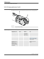
ABB IRB 1600 - 7/1.2 User manual
- Category
- Robotics
- Type
- User manual
This manual is also suitable for

Product manual
Articulated robot
IRB 1600 - 5/1.2
IRB 1600 - 5/1.45
IRB 1600 - 7/1.2
IRB 1600 - 7/1.45
M2004


Product manual
IRB 1600 - 5/1.2
IRB 1600 - 5/1.45
IRB 1600 - 7/1.2
IRB 1600 - 7/1.45
M2004
Document ID: 3HAC023637-001
Revision: B

The information in this manual is subject to change without notice and should not be
construed as a commitment by ABB. ABB assumes no responsibility for any errors that
may appear in this manual.
Except as may be expressly stated anywhere in this manual, nothing herein shall be
construed as any kind of guarantee or warranty by ABB for losses, damages to persons
or property, fitness for a specific purpose or the like.
In no event shall ABB be liable for incidental or consequential damages arising from
use of this manual and products described herein.
This manual and parts thereof must not be reproduced or copied without ABB's written
permission, and contents thereof must not be imparted to a third party nor be used for
any unauthorized purpose. Contravention will be prosecuted.
Additional copies of this manual may be obtained from ABB at its then current charge.
© Copyright 2005-2008 ABB All right reserved.
ABB Automation Technologies AB
Robotics
SE-721 68 Västerås
Sweden

Table of Contents
Overview . . . . . . . . . . . . . . . . . . . . . . . . . . . . . . . . . . . . . . . . . . . . . . . . . . . . . . . . . . . . . . . . . . . . . . . . . . . . . 7
Product documentation, M2004 . . . . . . . . . . . . . . . . . . . . . . . . . . . . . . . . . . . . . . . . . . . . . . . . . . . . . . . . . . . . 9
How to read the product manual. . . . . . . . . . . . . . . . . . . . . . . . . . . . . . . . . . . . . . . . . . . . . . . . . . . . . . . . . . . 11
1 Safety 13
1.1 Introduction . . . . . . . . . . . . . . . . . . . . . . . . . . . . . . . . . . . . . . . . . . . . . . . . . . . . . . . . . . . . . . . . . . . . . . . 13
1.2 General safety information. . . . . . . . . . . . . . . . . . . . . . . . . . . . . . . . . . . . . . . . . . . . . . . . . . . . . . . . . . . 14
1.2.1 Safety in the robot system . . . . . . . . . . . . . . . . . . . . . . . . . . . . . . . . . . . . . . . . . . . . . . . . . . . . . . . 14
1.2.2 Safety risks . . . . . . . . . . . . . . . . . . . . . . . . . . . . . . . . . . . . . . . . . . . . . . . . . . . . . . . . . . . . . . . . . . 15
1.2.2.1 Safety risks during installation and service work on robot. . . . . . . . . . . . . . . . . . . . . . . . 15
1.2.2.2 Safety risks related to tools/workpieces . . . . . . . . . . . . . . . . . . . . . . . . . . . . . . . . . . . . . . 17
1.2.2.3 Safety risks related to pneumatic/hydraulic systems. . . . . . . . . . . . . . . . . . . . . . . . . . . . . 18
1.2.2.4 Safety risks during operational disturbances. . . . . . . . . . . . . . . . . . . . . . . . . . . . . . . . . . . 19
1.2.2.5 Risks associated with live electric parts . . . . . . . . . . . . . . . . . . . . . . . . . . . . . . . . . . . . . . 20
1.2.3 Safety actions . . . . . . . . . . . . . . . . . . . . . . . . . . . . . . . . . . . . . . . . . . . . . . . . . . . . . . . . . . . . . . . . 21
1.2.3.1 Safety fence dimensions . . . . . . . . . . . . . . . . . . . . . . . . . . . . . . . . . . . . . . . . . . . . . . . . . . 21
1.2.3.2 Fire extinguishing . . . . . . . . . . . . . . . . . . . . . . . . . . . . . . . . . . . . . . . . . . . . . . . . . . . . . . . 22
1.2.3.3 Emergency release of the robot’s arm . . . . . . . . . . . . . . . . . . . . . . . . . . . . . . . . . . . . . . . 23
1.2.3.4 Brake testing . . . . . . . . . . . . . . . . . . . . . . . . . . . . . . . . . . . . . . . . . . . . . . . . . . . . . . . . . . . 24
1.2.3.5 Risk of disabling function "Reduced speed 250 mm/s" . . . . . . . . . . . . . . . . . . . . . . . . . . 25
1.2.3.6 Safe use of the Teach Pendant Unit . . . . . . . . . . . . . . . . . . . . . . . . . . . . . . . . . . . . . . . . . 26
1.2.3.7 Work inside the manipulator's working range . . . . . . . . . . . . . . . . . . . . . . . . . . . . . . . . . 27
1.2.3.8 Translate the information on safety and information labels . . . . . . . . . . . . . . . . . . . . . . . 28
1.3 Safety related instructions. . . . . . . . . . . . . . . . . . . . . . . . . . . . . . . . . . . . . . . . . . . . . . . . . . . . . . . . . . . 29
1.3.1 Safety signals, general . . . . . . . . . . . . . . . . . . . . . . . . . . . . . . . . . . . . . . . . . . . . . . . . . . . . . . . . . . 29
1.3.2 DANGER - Moving manipulators are potentially lethal! . . . . . . . . . . . . . . . . . . . . . . . . . . . . . . . 31
1.3.3 DANGER - First test run may cause injury or damage! . . . . . . . . . . . . . . . . . . . . . . . . . . . . . . . . 32
1.3.4 WARNING - The brake release buttons may be jammed after service work . . . . . . . . . . . . . . . . 33
1.3.5 WARNING - The unit is sensitive to ESD! . . . . . . . . . . . . . . . . . . . . . . . . . . . . . . . . . . . . . . . . . .34
1.3.6 WARNING - Safety risks during work with gearbox oil. . . . . . . . . . . . . . . . . . . . . . . . . . . . . . . . 35
2 Installation and commissioning 37
2.1 Introduction . . . . . . . . . . . . . . . . . . . . . . . . . . . . . . . . . . . . . . . . . . . . . . . . . . . . . . . . . . . . . . . . . . . . . . . 37
2.2 Unpacking . . . . . . . . . . . . . . . . . . . . . . . . . . . . . . . . . . . . . . . . . . . . . . . . . . . . . . . . . . . . . . . . . . . . . . . . 38
2.2.1 Pre-installation procedure. . . . . . . . . . . . . . . . . . . . . . . . . . . . . . . . . . . . . . . . . . . . . . . . . . . . . . . . 38
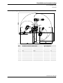
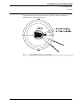
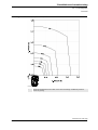
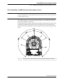
2.2.2 Working range . . . . . . . . . . . . . . . . . . . . . . . . . . . . . . . . . . . . . . . . . . . . . . . . . . . . . . . . . . . . . . . . 40
2.3 On-site installation . . . . . . . . . . . . . . . . . . . . . . . . . . . . . . . . . . . . . . . . . . . . . . . . . . . . . . . . . . . . . . . . . 44
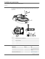
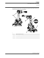
2.3.1 Lifting robot with roundsling . . . . . . . . . . . . . . . . . . . . . . . . . . . . . . . . . . . . . . . . . . . . . . . . . . . . . 44
2.3.2 Manually releasing the brakes . . . . . . . . . . . . . . . . . . . . . . . . . . . . . . . . . . . . . . . . . . . . . . . . . . . . 46
2.3.3 Orienting and securing the robot . . . . . . . . . . . . . . . . . . . . . . . . . . . . . . . . . . . . . . . . . . . . . . . . . . 48
2.3.4 Suspended mounting . . . . . . . . . . . . . . . . . . . . . . . . . . . . . . . . . . . . . . . . . . . . . . . . . . . . . . . . . . . 51
2.3.5 Load diagrams . . . . . . . . . . . . . . . . . . . . . . . . . . . . . . . . . . . . . . . . . . . . . . . . . . . . . . . . . . . . . . . . 54
2.3.6 Loads . . . . . . . . . . . . . . . . . . . . . . . . . . . . . . . . . . . . . . . . . . . . . . . . . . . . . . . . . . . . . . . . . . . . . . . 59
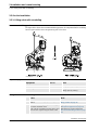
2.3.7 Fitting equipment on the robot (robot dimensions) . . . . . . . . . . . . . . . . . . . . . . . . . . . . . . . . . . . . 60
2.3.8 Installation of signal lamp (option) . . . . . . . . . . . . . . . . . . . . . . . . . . . . . . . . . . . . . . . . . . . . . . . . 64
2.4 Restricting the working range . . . . . . . . . . . . . . . . . . . . . . . . . . . . . . . . . . . . . . . . . . . . . . . . . . . . . . . . 66
2.4.1 Introduction . . . . . . . . . . . . . . . . . . . . . . . . . . . . . . . . . . . . . . . . . . . . . . . . . . . . . . . . . . . . . . . . . . 66
2.4.2 Installation of additional mechanical stops on axis 1. . . . . . . . . . . . . . . . . . . . . . . . . . . . . . . . . . .67
2.4.3 Installation of additional mechanical stop on axis 2 . . . . . . . . . . . . . . . . . . . . . . . . . . . . . . . . . . .70
2.4.4 Installation of additional mechanical stops on axis 3. . . . . . . . . . . . . . . . . . . . . . . . . . . . . . . . . . .73
2.4.5 Installation of position switch, axis 1. . . . . . . . . . . . . . . . . . . . . . . . . . . . . . . . . . . . . . . . . . . . . . . 76
2.5 Electrical connections . . . . . . . . . . . . . . . . . . . . . . . . . . . . . . . . . . . . . . . . . . . . . . . . . . . . . . . . . . . . . . 79
2.5.1 Connectors on robot . . . . . . . . . . . . . . . . . . . . . . . . . . . . . . . . . . . . . . . . . . . . . . . . . . . . . . . . . . . . 79

Table of Contents
2.5.2 Robot cabling and connection points. . . . . . . . . . . . . . . . . . . . . . . . . . . . . . . . . . . . . . . . . . . . . . . 80
2.5.3 Customer connections on the robot . . . . . . . . . . . . . . . . . . . . . . . . . . . . . . . . . . . . . . . . . . . . . . . . 82
3 Maintenance 85
3.1 Introduction . . . . . . . . . . . . . . . . . . . . . . . . . . . . . . . . . . . . . . . . . . . . . . . . . . . . . . . . . . . . . . . . . . . . . . . 85
3.2 Maintenance schedule and expected component life. . . . . . . . . . . . . . . . . . . . . . . . . . . . . . . . . . . . . 86
3.2.1 Specification of maintenance intervals . . . . . . . . . . . . . . . . . . . . . . . . . . . . . . . . . . . . . . . . . . . . . 86
3.2.2 Maintenance schedule . . . . . . . . . . . . . . . . . . . . . . . . . . . . . . . . . . . . . . . . . . . . . . . . . . . . . . . . . . 87
3.2.3 Expected component life . . . . . . . . . . . . . . . . . . . . . . . . . . . . . . . . . . . . . . . . . . . . . . . . . . . . . . . . 88
3.3 Inspection activities . . . . . . . . . . . . . . . . . . . . . . . . . . . . . . . . . . . . . . . . . . . . . . . . . . . . . . . . . . . . . . . . 89
3.3.1 Inspection, damper axes 2, 3 and 5 . . . . . . . . . . . . . . . . . . . . . . . . . . . . . . . . . . . . . . . . . . . . . . . . 89
3.4 Replacement activities. . . . . . . . . . . . . . . . . . . . . . . . . . . . . . . . . . . . . . . . . . . . . . . . . . . . . . . . . . . . . . 91
3.4.1 Oil in gearboxes . . . . . . . . . . . . . . . . . . . . . . . . . . . . . . . . . . . . . . . . . . . . . . . . . . . . . . . . . . . . . . . 91
3.4.2 Oil change, gearbox axes 5 and 6. . . . . . . . . . . . . . . . . . . . . . . . . . . . . . . . . . . . . . . . . . . . . . . . . . 92
3.4.3 Replacement of measurement system battery pack . . . . . . . . . . . . . . . . . . . . . . . . . . . . . . . . . . . . 95
3.5 Cleaning activities . . . . . . . . . . . . . . . . . . . . . . . . . . . . . . . . . . . . . . . . . . . . . . . . . . . . . . . . . . . . . . . . . 97
3.5.1 Cleaning, complete robot . . . . . . . . . . . . . . . . . . . . . . . . . . . . . . . . . . . . . . . . . . . . . . . . . . . . . . . . 97
4 Repair 99
4.1 Introduction . . . . . . . . . . . . . . . . . . . . . . . . . . . . . . . . . . . . . . . . . . . . . . . . . . . . . . . . . . . . . . . . . . . . . . . 99
4.2 General procedures . . . . . . . . . . . . . . . . . . . . . . . . . . . . . . . . . . . . . . . . . . . . . . . . . . . . . . . . . . . . . . . 100
4.2.1 Performing a leak-down test . . . . . . . . . . . . . . . . . . . . . . . . . . . . . . . . . . . . . . . . . . . . . . . . . . . . 100
4.2.2 Mounting instructions for bearings . . . . . . . . . . . . . . . . . . . . . . . . . . . . . . . . . . . . . . . . . . . . . . . 101
4.2.3 Mounting instructions for seals . . . . . . . . . . . . . . . . . . . . . . . . . . . . . . . . . . . . . . . . . . . . . . . . . . 102
4.3 Complete manipulator . . . . . . . . . . . . . . . . . . . . . . . . . . . . . . . . . . . . . . . . . . . . . . . . . . . . . . . . . . . . . 104
4.3.1 Replacement of cable harness . . . . . . . . . . . . . . . . . . . . . . . . . . . . . . . . . . . . . . . . . . . . . . . . . . . 104
4.3.2 Replacement of complete arm system . . . . . . . . . . . . . . . . . . . . . . . . . . . . . . . . . . . . . . . . . . . . . 113
4.4 Upper and lower arm . . . . . . . . . . . . . . . . . . . . . . . . . . . . . . . . . . . . . . . . . . . . . . . . . . . . . . . . . . . . . . 117
4.4.1 Replacement of complete upper arm . . . . . . . . . . . . . . . . . . . . . . . . . . . . . . . . . . . . . . . . . . . . . . 117
4.4.2 Replacement of complete lower arm . . . . . . . . . . . . . . . . . . . . . . . . . . . . . . . . . . . . . . . . . . . . . . 121
4.4.3 Replacement of wrist unit . . . . . . . . . . . . . . . . . . . . . . . . . . . . . . . . . . . . . . . . . . . . . . . . . . . . . . 125
4.4.4 Replacement of damper, axis 2 . . . . . . . . . . . . . . . . . . . . . . . . . . . . . . . . . . . . . . . . . . . . . . . . . . 128
4.4.5 Replacement of damper, axis 3 . . . . . . . . . . . . . . . . . . . . . . . . . . . . . . . . . . . . . . . . . . . . . . . . . . 130
4.4.6 Replacement of damper, axis 5 . . . . . . . . . . . . . . . . . . . . . . . . . . . . . . . . . . . . . . . . . . . . . . . . . . 132
4.5 Frame and base . . . . . . . . . . . . . . . . . . . . . . . . . . . . . . . . . . . . . . . . . . . . . . . . . . . . . . . . . . . . . . . . . . 134
4.5.1 Replacement of base . . . . . . . . . . . . . . . . . . . . . . . . . . . . . . . . . . . . . . . . . . . . . . . . . . . . . . . . . . 134
4.5.2 Replacement of serial measurement unit . . . . . . . . . . . . . . . . . . . . . . . . . . . . . . . . . . . . . . . . . . . 138
4.5.3 Replacement of push button unit . . . . . . . . . . . . . . . . . . . . . . . . . . . . . . . . . . . . . . . . . . . . . . . . . 142
4.6 Motors . . . . . . . . . . . . . . . . . . . . . . . . . . . . . . . . . . . . . . . . . . . . . . . . . . . . . . . . . . . . . . . . . . . . . . . . . . 146
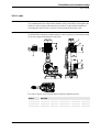
4.6.1 Replacement of motor, axis 1. . . . . . . . . . . . . . . . . . . . . . . . . . . . . . . . . . . . . . . . . . . . . . . . . . . . 146
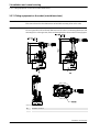
4.6.2 Replacement of motor, axis 2. . . . . . . . . . . . . . . . . . . . . . . . . . . . . . . . . . . . . . . . . . . . . . . . . . . . 150
4.6.3 Replacement of motor, axis 3. . . . . . . . . . . . . . . . . . . . . . . . . . . . . . . . . . . . . . . . . . . . . . . . . . . . 154
4.6.4 Replacement of motor, axis 4. . . . . . . . . . . . . . . . . . . . . . . . . . . . . . . . . . . . . . . . . . . . . . . . . . . . 158
4.6.5 Replacement of motor and timing belt, axis 5 . . . . . . . . . . . . . . . . . . . . . . . . . . . . . . . . . . . . . . . 161
4.6.6 Replacement of motor and timing belt, axis 6 . . . . . . . . . . . . . . . . . . . . . . . . . . . . . . . . . . . . . . . 165
4.7 Gearboxes . . . . . . . . . . . . . . . . . . . . . . . . . . . . . . . . . . . . . . . . . . . . . . . . . . . . . . . . . . . . . . . . . . . . . . . 169
4.7.1 Replacement of gearbox, axes 1-2 . . . . . . . . . . . . . . . . . . . . . . . . . . . . . . . . . . . . . . . . . . . . . . . 169
4.7.2 Service work on gearboxes, axes 3, 4, 5 and 6 . . . . . . . . . . . . . . . . . . . . . . . . . . . . . . . . . . . . . . 173
5 Calibration information 175
5.1 Introduction . . . . . . . . . . . . . . . . . . . . . . . . . . . . . . . . . . . . . . . . . . . . . . . . . . . . . . . . . . . . . . . . . . . . . . 175
5.2 Calibration methods . . . . . . . . . . . . . . . . . . . . . . . . . . . . . . . . . . . . . . . . . . . . . . . . . . . . . . . . . . . . . . . . 176

Table of Contents
5.3 Calibration scales and correct axis position . . . . . . . . . . . . . . . . . . . . . . . . . . . . . . . . . . . . . . . . . . . . . . 178
5.4 Calibration movement directions for all axes. . . . . . . . . . . . . . . . . . . . . . . . . . . . . . . . . . . . . . . . . . . . . 179
5.5 Updating revolution counters . . . . . . . . . . . . . . . . . . . . . . . . . . . . . . . . . . . . . . . . . . . . . . . . . . . . . . . . . 180
5.6 Checking the calibration position . . . . . . . . . . . . . . . . . . . . . . . . . . . . . . . . . . . . . . . . . . . . . . . . . . . . . 183
Overview . . . . . . . . . . . . . . . . . . . . . . . . . . . . . . . . . . . . . . . . . . . . . . . . . . . . . . . . . . . . . . . . . . . . . . . . . . . 185
6 Reference information 187
6.1 Introduction . . . . . . . . . . . . . . . . . . . . . . . . . . . . . . . . . . . . . . . . . . . . . . . . . . . . . . . . . . . . . . . . . . . . . . 187
6.2 Applicable safety standards . . . . . . . . . . . . . . . . . . . . . . . . . . . . . . . . . . . . . . . . . . . . . . . . . . . . . . . . . . 188
6.3 Unit conversion. . . . . . . . . . . . . . . . . . . . . . . . . . . . . . . . . . . . . . . . . . . . . . . . . . . . . . . . . . . . . . . . . . . . 189
6.4 Screw joints . . . . . . . . . . . . . . . . . . . . . . . . . . . . . . . . . . . . . . . . . . . . . . . . . . . . . . . . . . . . . . . . . . . . . . 190
6.5 Weight specifications . . . . . . . . . . . . . . . . . . . . . . . . . . . . . . . . . . . . . . . . . . . . . . . . . . . . . . . . . . . . . . . 193
6.6 Standard toolkit. . . . . . . . . . . . . . . . . . . . . . . . . . . . . . . . . . . . . . . . . . . . . . . . . . . . . . . . . . . . . . . . . . . . 194
6.7 Special tools . . . . . . . . . . . . . . . . . . . . . . . . . . . . . . . . . . . . . . . . . . . . . . . . . . . . . . . . . . . . . . . . . . . . . . 195
6.8 Lifting equipment and lifting instructions . . . . . . . . . . . . . . . . . . . . . . . . . . . . . . . . . . . . . . . . . . . . . . . 196
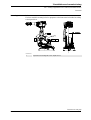
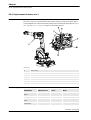
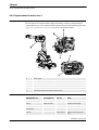
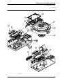
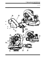
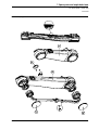
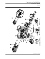
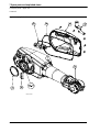
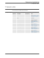
7 Spare parts and exploded views 197
7.1 Introduction . . . . . . . . . . . . . . . . . . . . . . . . . . . . . . . . . . . . . . . . . . . . . . . . . . . . . . . . . . . . . . . . . . . . . . 197
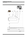
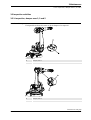
7.2 Spare parts - base . . . . . . . . . . . . . . . . . . . . . . . . . . . . . . . . . . . . . . . . . . . . . . . . . . . . . . . . . . . . . . . . . . 198
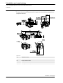
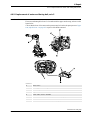
7.3 Spare parts - base connections . . . . . . . . . . . . . . . . . . . . . . . . . . . . . . . . . . . . . . . . . . . . . . . . . . . . . . . . 200
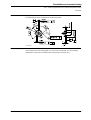
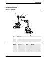
7.4 Spare parts - frame . . . . . . . . . . . . . . . . . . . . . . . . . . . . . . . . . . . . . . . . . . . . . . . . . . . . . . . . . . . . . . . . . 202
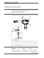
7.5 Spare parts - lower arm. . . . . . . . . . . . . . . . . . . . . . . . . . . . . . . . . . . . . . . . . . . . . . . . . . . . . . . . . . . . . . 204
7.6 Spare parts - upper arm. . . . . . . . . . . . . . . . . . . . . . . . . . . . . . . . . . . . . . . . . . . . . . . . . . . . . . . . . . . . . . 206
7.7 Spare parts - options . . . . . . . . . . . . . . . . . . . . . . . . . . . . . . . . . . . . . . . . . . . . . . . . . . . . . . . . . . . . . . . . 209
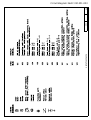
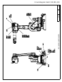
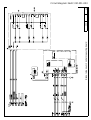
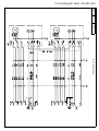
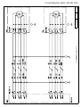
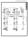
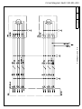
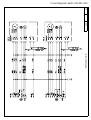
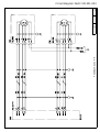
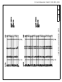
8 Circuit diagram 211
8.1 Introduction . . . . . . . . . . . . . . . . . . . . . . . . . . . . . . . . . . . . . . . . . . . . . . . . . . . . . . . . . . . . . . . . . . . . . . 211
Index 213

Table of Contents

Overview
73HAC023637-001 Revision: B
Overview
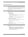
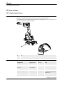
About this manual
This manual contains instructions for:
• mechanical and electrical installation of the robot
• maintenance of the robot
• mechanical and electrical repair of the robot.
Usage
This manual should be used during:
• installation, from lifting the robot to its work site and securing it to the foundation, to
making it ready for operation
• maintenance work
• repair work and calibration.
Who should read this manual?
This manual is intended for:
• installation personnel
• maintenance personnel
• repair personnel.
Prerequisites
A maintenance/repair/ installation craftsman working with an ABB Robot must:
• be trained by ABB and have the required knowledge of mechanical and electrical
installation/repair/maintenance work.
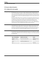
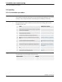
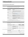
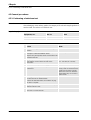
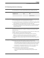
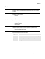
Organization of chapters
The manual is organized in the following chapters:
Chapter Contents
Safety, service Safety information that must be read through before performing
any installation or service work on robot. Contains general safety
aspects as well as more specific information on how to avoid
personal injuries and damage to the product.
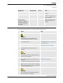
Installation and commis-
sioning
Required information about lifting and installation of the robot.
Maintenance Step-by-step procedures that describe how to perform
maintenance of the robot. Based on a maintenance schedule
that may be used to plan periodical maintenance.
Repair Step-by-step procedures that describe how to perform repair
activities of the robot. Based on available spare parts.
Calibration information Procedures that do not require specific calibration equipment.
General information about calibration.
Continues on next page

Overview
3HAC023637-001 Revision: B8
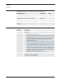
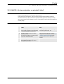
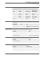
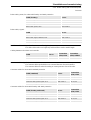
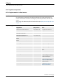
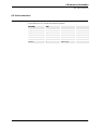
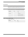
References
Documentation referred to in the manual, is listed in the table below.
Revisions
Document name Document ID Note
Product specification - IRB 1600 3HAC023604-001
Product manual - IRC5 3HAC021313-001
Operating manual - IRC5 with FlexPendant 3HAC16590-1
Operating manual - Calibration Pendulum 3HAC16578-1
Operating manual - Service Information System 3HAC025709-001
Application manual - Additional axes and stand alone
controller
3HAC021395-001
Technical reference manual - System parameters 3HAC17076-1
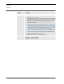
Revision Description
- First edition.
A • Document references are moved from a separate section to the
table References on page 8.
• Information about changing working range limitations in the software
is added to the sections in Restricting the working range on page 66.
• Information about the alternative calibration method (Levelmeter
2000) is removed from the manual, since the method is not
supported for the robot.
• Safety information is added to the procedures Replacement of push
button unit on page 142, Replacement of serial measurement unit
on page 138 and Replacement of cable harness on page 104. Also,
a new section is added to the chapter Safety, WARNING - The brake
release buttons may be jammed after service work on page 33.
• Connector set for standard customer connection is added to section
Customer connections on the robot on page 82. Incorrect article
number for Soriau pin is also corrected and information about pin
diameter is added, in the same section.
• New section: Suspended mounting on page 51.
B Changes made in:
Prerequisites in section Owerview
Oil change in section Maintenance
Continued

Product documentation, M2004
93HAC023637-001 Revision: B
Product documentation, M2004
General
The robot documentation may be divided into a number of categories. This listing is based on
the type of information contained within the documents, regardless of whether the products
are standard or optional. This means that any given delivery of robot products will not contain
all documents listed, only the ones pertaining to the equipment delivered.
However, all documents listed may be ordered from ABB. The documents listed are valid for
M2004 robot systems.
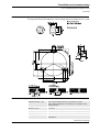
Product manuals
All hardware, robots and controller cabinets, will be delivered with a Product manual which
is divided into two parts:
Product manual, procedures
• Safety information
• Installation and commissioning (descriptions of mechanical installation, electrical
connections and loading system software)
• Maintenance (descriptions of all required preventive maintenance procedures
including intervals)
• Repair (descriptions of all recommended repair procedures including spare parts)
• Additional procedures, if any (calibration, decommissioning)
Product manual, reference information
• Reference information (article numbers for documentation referred to in Product
manual, procedures, lists of tools, safety standards)
• Part list
• Foldouts or exploded views
• Circuit diagrams
The product manual published as a PDF consists of only one file where the two parts are
presented together, as one Product manual.
RobotWare manuals
The following manuals describe the robot software in general and contain relevant reference
information:
• RAPID Overview: An overview of the RAPID programming language.
• Technical reference manual - RAPID Instructions, functions and data types:
Description and syntax for all RAPID instructions, functions and data types.
• Technical reference manual - System parameters: Description of system
parameters and configuration workflows.
Continues on next page

Product documentation, M2004
3HAC023637-001 Revision: B10
Application manuals
Specific applications (e.g. software or hardware options) are described in Application
manuals. An application manual can describe one or several applications.
An application manual generally contains information about:
• The purpose of the application (what it does and when it is useful)
• What is included (e.g. cables, I/O boards, RAPID instructions, system parameters)
• How to use the application
• Examples of how to use the application
Operating manuals
This group of manuals is aimed at those having first hand operational contact with the robot,
i.e. production cell operators, programmers and trouble shooters. The group of manuals
includes:
• Getting started - IRC5 and RobotStudio Online
• Operating manual - IRC5 with FlexPendant
• Operating manual - RobotStudio Online
• Trouble shooting manual for the controller and robot
Continued

How to read the product manual
113HAC023637-001 Revision: B
How to read the product manual
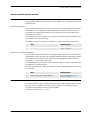
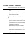
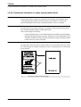
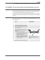
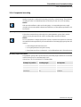
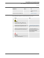
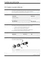
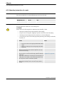
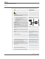
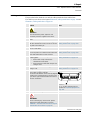
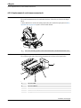
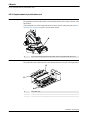
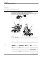
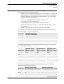
Reading the procedures
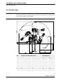
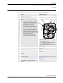
The procedures contain references to figures, tools, material etc. The references are read as
described below.
References to figures
The procedures often include references to components or attachment points located on the
robot/controller. The components or attachment points are marked with italic text in the
procedures and completed with a reference to the figure where the current component or
attachment point is shown.
The denomination in the procedure for the component or attachment point corresponds to the
denomination in the referenced figure.
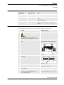
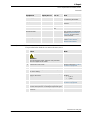
The table below shows an example of a reference to a figure from a step in a procedure.
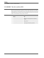
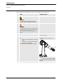
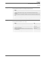
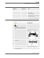
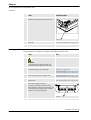
References to required equipment
The procedures often include references to equipment (spare parts, tools etc.) required for the
different actions in the procedure. The equipment is marked with italic text in the procedures
and completed with a reference to the section where the equipment is listed with further
information, i.e. article number, dimension.
The denomination in the procedure for the component or attachment point corresponds to the
denomination in the referenced list.
The table below shows an example of a reference to a list of required equipment, from a step
in a procedure.
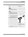
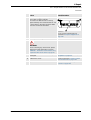
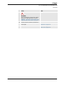
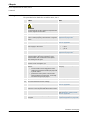
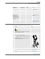
Safety information
The manual includes a separate safety chapter that must be read through before proceeding
with any service or installation procedures. All procedures also include specific safety
information when dangerous steps are to be performed.
Read more in chapter Safety on page 13.
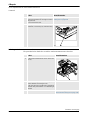
Action Note/Illustration
8. Remove the rear attachment screws, gearbox. Shown in the figure Location of
gearbox on page xx.
Action Note/Illustration
3. Fit a new sealing, axis 2 to the gearbox. Art. no. is specified in Required
equipment on page xx.

How to read the product manual
3HAC023637-001 Revision: B12

1 Safety
1.1. Introduction
133HAC023637-001 Revision: B
1 Safety
1.1. Introduction
Overview
The safety information in this manual is divided in two categories:
• general safety aspects, important to attend to before performing any service work on
the robot. These are applicable for all service work and are found in section General
safety information on page 14.
• specific safety information, pointed out in the procedure at the moment of the danger.
How to avoid and eliminate the danger is either detailed directly in the procedure, or
further detailed in separate instructions, found in section Safety related instructions on
page 29.

1 Safety
1.2.1. Safety in the robot system
3HAC023637-001 Revision: B14
1.2 General safety information
1.2.1. Safety in the robot system
Validity and responsibility
The information does not cover how to design, install and operate a complete system, nor
does it cover all peripheral equipment, which can influence the safety of the total system. To
protect personnel, the complete system must be designed and installed in accordance with the
safety requirements set forth in the standards and regulations of the country where the robot
is installed.
The users of ABB industrial robots are responsible for ensuring that the applicable safety laws
and regulations in the country concerned are observed and that the safety devices necessary
to protect people working with the robot system are designed and installed correctly.
Personnel working with robots must be familiar with the operation and handling of the
industrial robot, described in the applicable documents, e.g. User’s guide - S4Cplus (M2000)
/ Operating manual - IRC5 with FlexPendant (M2004) and Product manual.
Connection of external safety devices
Apart from the built-in safety functions, the robot is also supplied with an interface for the
connection of external safety devices. Via this interface, an external safety function can
interact with other machines and peripheral equipment. This means that control signals can
act on safety signals received from the peripheral equipment as well as from the robot.
Limitation of liability
Any information given in this manual regarding safety, must not be construed as a warranty
by ABB that the industrial robot will not cause injury or damage even if all safety instructions
are complied with.
Related information
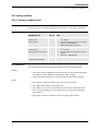
Type of information Detailed in document Section
Installation of safety
devices
Product manual for the robot Installation and com-
missioning
Changing operating
modes
Operating manual - IRC5 with
FlexPendant (RobotWare 5.0)
Operating modes
Restricting the working
space
Product manual for the robot Installation and com-
missioning

1 Safety
1.2.2.1. Safety risks during installation and service work on robot
153HAC023637-001 Revision: B
1.2.2. Safety risks
1.2.2.1. Safety risks during installation and service work on robot
Overview
This section includes information of general safety risks to be considered when performing
installation and service work on the robot.
General risks during installation and service
• The instructions in the Product Manual - Installation and Commissioning must always
be followed.
• Emergency stop buttons must be positioned in easily accessible places so that the robot
can be stopped quickly.
• Those in charge of operations must make sure that safety instructions are available for
the installation in question.
• Those who install the robot must have the appropriate training for the robot system in
question and in any safety matters associated with it.
Nation/region specific regulations
To prevent injuries and damage during the installation of the robot system, the regulations
applicable in the country concerned and the instructions of ABB Robotics must be complied
with.
Non-voltage related risks
• Safety zones, which have to be crossed before admittance, must be set up in front of
the robot's working space. Light beams or sensitive mats are suitable devices.
• Turntables or the like should be used to keep the operator out of the robot's working
space.
• The axes are affected by the force of gravity when the brakes are released. In addition
to the risk of being hit by moving robot parts, you run the risk of being crushed by the
parallel arm.
• Energy, stored in the robot for the purpose of counterbalancing certain axes, may be
released if the robot, or parts thereof, are dismantled.
• When dismantling/assembling mechanical units, watch out for falling objects.
• Be aware of stored heat energy in the controller.
• Never use the robot as a ladder, i.e. do not climb on the robot motors or other part
during service work. There is a serious risk of slipping because of the high temperature
of the motors or oil spills that can occur on the robot.
To be observed by the supplier of the complete system
• The supplier of the complete system must ensure that all circuits used in the safety
function are interlocked in accordance with the applicable standards for that function.
• The supplier of the complete system must ensure that all circuits used in the
emergency stop function are interlocked in a safe manner, in accordance with the
applicable standards for the emergency stop function.
Continues on next page

1 Safety
1.2.2.1. Safety risks during installation and service work on robot
3HAC023637-001 Revision: B16
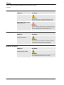
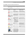
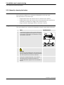
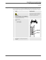
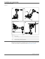
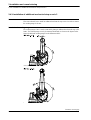
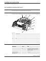
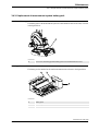
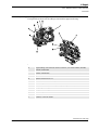
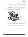
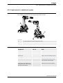
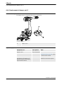
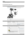
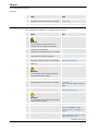
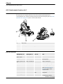
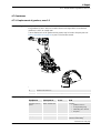
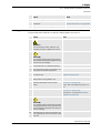
Complete robot
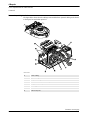
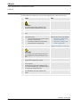
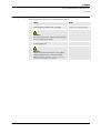
Cabling
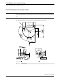
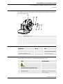
Gearboxes and motors
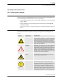
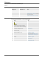
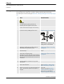
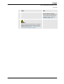
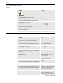
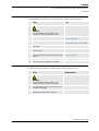
Safety risk Description
Hot components!
CAUTION!
Motors and gears are HOT after running the robot!
Touching the motors and gears may result in burns!
Removed parts may result in
collapse of robot!
WARNING!
Take any necessary measures to ensure that the robot
does not collapse as parts are removed, e.g. secure the
lower arm with fixtures if removing motor, axis 2.
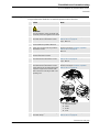
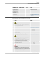
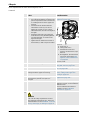
Safety risk Description
Cable packs are sensitive to
mechanical damage!
CAUTION!
The cable packs are sensitive to mechanical damage!
They must be handled with care, especially the
connectors, in order to avoid damaging them!
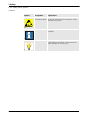
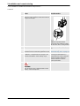
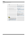
Safety risk Description
Gears may be damaged if
excessive force is used!
CAUTION!
Whenever parting/mating motor and gearbox, the gears
may be damaged if excessive force is used!
Continued

1 Safety
1.2.2.2. Safety risks related to tools/workpieces
173HAC023637-001 Revision: B
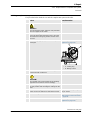
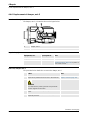
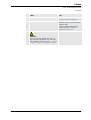
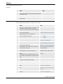
1.2.2.2. Safety risks related to tools/workpieces
Safe handling
It must be possible to safely turn off tools, such as milling cutters, etc. Make sure that guards
remain closed until the cutters stop rotating.
It should be possible to release parts by manual operation (valves).
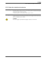
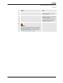
Safe design
Grippers/end effectors must be designed so that they retain workpieces in the event of a power
failure or a disturbance of the controller.
CAUTION!
Ensure that a gripper is prevented from dropping a workpiece, if such is used.

1 Safety
1.2.2.3. Safety risks related to pneumatic/hydraulic systems
3HAC023637-001 Revision: B18
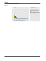
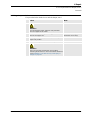
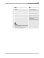
1.2.2.3. Safety risks related to pneumatic/hydraulic systems
General
Special safety regulations apply to pneumatic and hydraulic systems.
Residual energy
• Residual energy may be present in these systems. After shutdown, particular care must
be taken.
• The pressure in pneumatic and hydraulic systems must be released before starting to
repair them.
Safe design
• Gravity may cause any parts or objects held by these systems to drop.
• Dump valves should be used in case of emergency.
• Shot bolts should be used to prevent tools, etc., from falling due to gravity.
Page is loading ...
Page is loading ...
Page is loading ...
Page is loading ...
Page is loading ...
Page is loading ...
Page is loading ...
Page is loading ...
Page is loading ...
Page is loading ...
Page is loading ...
Page is loading ...
Page is loading ...
Page is loading ...
Page is loading ...
Page is loading ...
Page is loading ...
Page is loading ...
Page is loading ...
Page is loading ...
Page is loading ...
Page is loading ...
Page is loading ...
Page is loading ...
Page is loading ...
Page is loading ...
Page is loading ...
Page is loading ...
Page is loading ...
Page is loading ...
Page is loading ...
Page is loading ...
Page is loading ...
Page is loading ...
Page is loading ...
Page is loading ...
Page is loading ...
Page is loading ...
Page is loading ...
Page is loading ...
Page is loading ...
Page is loading ...
Page is loading ...
Page is loading ...
Page is loading ...
Page is loading ...
Page is loading ...
Page is loading ...
Page is loading ...
Page is loading ...
Page is loading ...
Page is loading ...
Page is loading ...
Page is loading ...
Page is loading ...
Page is loading ...
Page is loading ...
Page is loading ...
Page is loading ...
Page is loading ...
Page is loading ...
Page is loading ...
Page is loading ...
Page is loading ...
Page is loading ...
Page is loading ...
Page is loading ...
Page is loading ...
Page is loading ...
Page is loading ...
Page is loading ...
Page is loading ...
Page is loading ...
Page is loading ...
Page is loading ...
Page is loading ...
Page is loading ...
Page is loading ...
Page is loading ...
Page is loading ...
Page is loading ...
Page is loading ...
Page is loading ...
Page is loading ...
Page is loading ...
Page is loading ...
Page is loading ...
Page is loading ...
Page is loading ...
Page is loading ...
Page is loading ...
Page is loading ...
Page is loading ...
Page is loading ...
Page is loading ...
Page is loading ...
Page is loading ...
Page is loading ...
Page is loading ...
Page is loading ...
Page is loading ...
Page is loading ...
Page is loading ...
Page is loading ...
Page is loading ...
Page is loading ...
Page is loading ...
Page is loading ...
Page is loading ...
Page is loading ...
Page is loading ...
Page is loading ...
Page is loading ...
Page is loading ...
Page is loading ...
Page is loading ...
Page is loading ...
Page is loading ...
Page is loading ...
Page is loading ...
Page is loading ...
Page is loading ...
Page is loading ...
Page is loading ...
Page is loading ...
Page is loading ...
Page is loading ...
Page is loading ...
Page is loading ...
Page is loading ...
Page is loading ...
Page is loading ...
Page is loading ...
Page is loading ...
Page is loading ...
Page is loading ...
Page is loading ...
Page is loading ...
Page is loading ...
Page is loading ...
Page is loading ...
Page is loading ...
Page is loading ...
Page is loading ...
Page is loading ...
Page is loading ...
Page is loading ...
Page is loading ...
Page is loading ...
Page is loading ...
Page is loading ...
Page is loading ...
Page is loading ...
Page is loading ...
Page is loading ...
Page is loading ...
Page is loading ...
Page is loading ...
Page is loading ...
Page is loading ...
Page is loading ...
Page is loading ...
Page is loading ...
Page is loading ...
Page is loading ...
Page is loading ...
Page is loading ...
Page is loading ...
Page is loading ...
Page is loading ...
Page is loading ...
Page is loading ...
Page is loading ...
Page is loading ...
Page is loading ...
Page is loading ...
Page is loading ...
Page is loading ...
Page is loading ...
Page is loading ...
Page is loading ...
Page is loading ...
Page is loading ...
Page is loading ...
Page is loading ...
Page is loading ...
Page is loading ...
Page is loading ...
Page is loading ...
Page is loading ...
Page is loading ...
Page is loading ...
Page is loading ...
Page is loading ...
Page is loading ...
Page is loading ...
Page is loading ...
Page is loading ...
Page is loading ...
Page is loading ...
Page is loading ...
Page is loading ...
Page is loading ...
Page is loading ...
Page is loading ...
Page is loading ...
Page is loading ...
Page is loading ...
Page is loading ...
Page is loading ...
Page is loading ...
Page is loading ...
Page is loading ...
Page is loading ...
-
 1
1
-
 2
2
-
 3
3
-
 4
4
-
 5
5
-
 6
6
-
 7
7
-
 8
8
-
 9
9
-
 10
10
-
 11
11
-
 12
12
-
 13
13
-
 14
14
-
 15
15
-
 16
16
-
 17
17
-
 18
18
-
 19
19
-
 20
20
-
 21
21
-
 22
22
-
 23
23
-
 24
24
-
 25
25
-
 26
26
-
 27
27
-
 28
28
-
 29
29
-
 30
30
-
 31
31
-
 32
32
-
 33
33
-
 34
34
-
 35
35
-
 36
36
-
 37
37
-
 38
38
-
 39
39
-
 40
40
-
 41
41
-
 42
42
-
 43
43
-
 44
44
-
 45
45
-
 46
46
-
 47
47
-
 48
48
-
 49
49
-
 50
50
-
 51
51
-
 52
52
-
 53
53
-
 54
54
-
 55
55
-
 56
56
-
 57
57
-
 58
58
-
 59
59
-
 60
60
-
 61
61
-
 62
62
-
 63
63
-
 64
64
-
 65
65
-
 66
66
-
 67
67
-
 68
68
-
 69
69
-
 70
70
-
 71
71
-
 72
72
-
 73
73
-
 74
74
-
 75
75
-
 76
76
-
 77
77
-
 78
78
-
 79
79
-
 80
80
-
 81
81
-
 82
82
-
 83
83
-
 84
84
-
 85
85
-
 86
86
-
 87
87
-
 88
88
-
 89
89
-
 90
90
-
 91
91
-
 92
92
-
 93
93
-
 94
94
-
 95
95
-
 96
96
-
 97
97
-
 98
98
-
 99
99
-
 100
100
-
 101
101
-
 102
102
-
 103
103
-
 104
104
-
 105
105
-
 106
106
-
 107
107
-
 108
108
-
 109
109
-
 110
110
-
 111
111
-
 112
112
-
 113
113
-
 114
114
-
 115
115
-
 116
116
-
 117
117
-
 118
118
-
 119
119
-
 120
120
-
 121
121
-
 122
122
-
 123
123
-
 124
124
-
 125
125
-
 126
126
-
 127
127
-
 128
128
-
 129
129
-
 130
130
-
 131
131
-
 132
132
-
 133
133
-
 134
134
-
 135
135
-
 136
136
-
 137
137
-
 138
138
-
 139
139
-
 140
140
-
 141
141
-
 142
142
-
 143
143
-
 144
144
-
 145
145
-
 146
146
-
 147
147
-
 148
148
-
 149
149
-
 150
150
-
 151
151
-
 152
152
-
 153
153
-
 154
154
-
 155
155
-
 156
156
-
 157
157
-
 158
158
-
 159
159
-
 160
160
-
 161
161
-
 162
162
-
 163
163
-
 164
164
-
 165
165
-
 166
166
-
 167
167
-
 168
168
-
 169
169
-
 170
170
-
 171
171
-
 172
172
-
 173
173
-
 174
174
-
 175
175
-
 176
176
-
 177
177
-
 178
178
-
 179
179
-
 180
180
-
 181
181
-
 182
182
-
 183
183
-
 184
184
-
 185
185
-
 186
186
-
 187
187
-
 188
188
-
 189
189
-
 190
190
-
 191
191
-
 192
192
-
 193
193
-
 194
194
-
 195
195
-
 196
196
-
 197
197
-
 198
198
-
 199
199
-
 200
200
-
 201
201
-
 202
202
-
 203
203
-
 204
204
-
 205
205
-
 206
206
-
 207
207
-
 208
208
-
 209
209
-
 210
210
-
 211
211
-
 212
212
-
 213
213
-
 214
214
-
 215
215
-
 216
216
-
 217
217
-
 218
218
-
 219
219
-
 220
220
-
 221
221
-
 222
222
-
 223
223
-
 224
224
-
 225
225
-
 226
226
-
 227
227
-
 228
228
-
 229
229
-
 230
230
-
 231
231
-
 232
232
-
 233
233
-
 234
234


ABB IRB 1600 - 7/1.2 User manual
- Category
- Robotics
- Type
- User manual
- This manual is also suitable for
Ask a question and I''ll find the answer in the document
Finding information in a document is now easier with AI
Related papers
Other documents
-
Coby TF-TV4028 Mounting Manual
-
Omron Washdown Delta Robots IP67 - R6Y3 Series Technical Owner's manual
-
-
-
-
Denso RC5 User manual
-
-
-
-
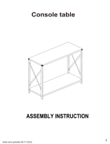 Baxton Studio LCF20330-Wood-Console Table Assembly Instructions
