Tekonsha 3026-P Installation guide

Type
Installation guide

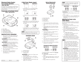
Tekonsha 3026-P is a vehicle stop lamp switch to brake controller adapter, allowing you to connect your electric trailer brake controller to your vehicle's wiring system. It features a 6-pin connector that mates with the one on the adapter and plugs into the mating receptacle on the backside of the brake control. This adapter is compatible with vehicles that have a 6-pin connector for the electric brake control harness.

Tekonsha 3026-P is a vehicle stop lamp switch to brake controller adapter, allowing you to connect your electric trailer brake controller to your vehicle's wiring system. It features a 6-pin connector that mates with the one on the adapter and plugs into the mating receptacle on the backside of the brake control. This adapter is compatible with vehicles that have a 6-pin connector for the electric brake control harness.

18289-037 Rev. A 03/22/07
ENGLISH
TOOLS REQUIRED:
Trim Panel Remover
CAUTION
Plug brake control adapter into mating
receptacle on backside of brake control
before attaching to the vehicle connector
d
.
1. Carefully remove vehicle trim panel
underneath dash making sure not to pull
on courtesy lamp wires that are attached
e
.
2. Locate the vehicle’s electric brake control
harness connector
f
. The harness will be
located underneath the dash and left of the
steering column, taped to another harness
near the emergency brake pedal. There will
be a 6-pin connector that mates with the
one on the adapter.
3. Plug the brake control adapter into the
vehicle electric controller connector
g
.
4. Complete the installation per the electric
brake control manufacturer’s instructions
and mount the unit as directed. Perform
test procedures as instructed.
NOTE
Vehicles not equipped with OEM trailer
tow package, may require fuses and relays
to complete output and battery feed circuits
(sold separately). Consult owners manual
for locations.
WARNING
Overloading circuit can cause fires. DO
NOT exceed lower of towing manufacturer
rating or:
• Max. 4 AXLES: 8 BRAKES (24 amps)
Read vehicle's owners manual &
instruction sheet for additional information.
TRAILER BRAKE CONTROLLER (OUTPUT)
CONTRÔLE DE FREIN DE REMORQUE (SORTIE)
CONDUCTOR DEL CONTROLADOR DE FRENO
(SALIDA) AL FRENO ELÉCTRICO DEL REMOLQUE
GROUND
MISE À LA TERRE
TIERRA
Installation Instructions
Directives de Montage
Instrucciones de Instalación
Electronic Trailer Brake Control
Wiring Adapter
Adaptateur pour câblage de commande
de frein de remorque électrique
Adaptador del cableado de control
eléctrico del remolque
d
e
f
g
READ THIS FIRST:
Read and follow all vehicle warnings and installation
instructions before beginning installation. Wear safety
glasses and use all safety precautions during installation.
LISEZ CECI EN PREMIER:
Lire et observer toutes les consignes de sécurité et les
instructions avant de commencer l’installation. Durant
l’installation, veiller à toujours porter des lunettes de
protection et respecter les mesures de sécurité.
LEA ESTO PRIMERO:
Lea y siga todas las advertencias e instrucciones de
instalación del vehículo antes de empezar la instalación.
Use gafas de seguridad y todas las precauciones de
seguridad durante la instalación.
FUSED TRAILER BRAKE CONTROLLLER
BATTERY FEED
ALIMENTATION À FUSIBLE DE
LA BATTERIE AU CONTRÔLE DE FREINS
CONDUCTOR (CON FUSIBLE) DE
LA BATERIA AL CONTROLADOR
DEL FRENO DEL REMOLQUE
Wiring Adapter Housing (containing Male Terminals) - Wire Side
Logement de l'adaptateur de câblage (contenant les bornes mâles) - Côté fil
Protector del adaptador de cables (contiene los terminales machos) - Alambre el lado
VEHICLE STOP LAMP SWITCH TO BRAKE CONTROLLER (INPUT)
COMMUTATEUR DE FEUX D'ARRÊT DU VÉHICULE AU CONTROLE DE FREINS
INTERRUPTOR DE LUCES DE FRENADO DEL VEHICULO AL CONTROLADO DE FRENO (ENTRADA)
© 2007 CequentElectrical Products
FRANÇAIS
OUTILS REQUIS:
Écarteur de panneau de garnisage
ATTENTION
Brancher l’adaptateur de la commande de
frein dans le réceptacle correspondant sur la
face arrière de la commande de frein avant
de le fixer au connecteur du véhicule
d
.
1. Retirer délicatement le panneau de
garnissage sous le tableau de bord, en
prenant soin de ne pas tirer sur les fils
de lampe d'accueil qui y sont attachés
e
.
2. Repérer le connecteur du faisceau de fils
de la commande de frein du véhicule
f
.
Le faisceau est situé sous le tableau de
bord, à gauche de la colonne de direction, et
il est fixé à un autre faisceau avec du ruban
adhésif à proximité de la pédale de frein. Un
connecteur à 6 broches qui correspond à
celui de l’adaptateur s’y trouve aussi.
3. Brancher l’adaptateur de la commande
de frein dans le connecteur du faisceau
de fils de la commande de frein électrique
du véhicule
g
.
4. Terminer l’installation en suivant les
instructions du fabricant de la commande
de frein électrique et monter l’appareil
comme indiqué. Effectuer les tests selon
les directives.
REMARQUE
Les véhicules qui ne sont pas équipés
d’un attelage de remorque OEM peuvent
requérir l’utilisation de fusibles et de relais
pour compléter les circuits de sortie et d’ali-
mentation de la batterie (vendu séparément).
Consultez le manuel du propriétaire pour
connaître les emplacements.
AVERTISSEMENT
Un circuit surchargé peut occasionner des
incendies. NE DÉPASSEZ JAMAIS la valeur
la plus basse indiquée par le fabricant de
remorquage, ou:
• Max. 4 ESSIEUX: 8 FREINS (24 ampères)
Consultez le manuel du propriétaire et la
feuille d’instructions du véhicule pour de plus
amples informations.
ESPAÑOL
HERRAMIENTAS NECESARIAS:
Corte el removedor de paneles
ATENCIÓN
Conecte el adaptador del control del freno en
el receptáculo correspondiente en el costado
posterior del control del freno antes de unirlo
al conector del vehículo
d
.
1. Con cuidado retire el panel de guarnición del
vehículo debajo del tablero, cerciorándose de
que no hale los cables de la luz de cortesía
que están unidos
e
.
2.
Localice el conector del arnés del control
del freno eléctrico del vehículo
f
. El arnés
estará localizado debajo del tablero y a la
izquierda de la columna de dirección, unido a
otro arnés cerca del pedal del freno de emer-
gencia. Habrá un conector de 6 patas que
corresponde con el que hay en el adaptador.
3. Conecte el adaptador del control del freno
en el conector del arnés del control del
freno eléctrico del vehículo
g
.
4. Complete la instalación según las instruc-
ciones del fabricante del control del freno
e instale la unidad según se indica. Realice
los procedimientos de prueba según
las instrucciones.
NOTA
Vehículos no equipados con el paquete de
remolque OEM pueden requerir de fusibles
y relés para completar los circuitos de salida
y alimentación de la batería (se vende por
separado). Consulte las ubicaciones en el
manual del propietario.
ADVERTENCIA
La sobrecarga del circuito puede ocasionar
incendios. NO exceda la calificación de
remolque más baja indicada por el
fabricante o:
• Máx. 4 EJES: 8 FRENOS (24 amperios)
Lea el manual del propietario y la
hoja de instrucciones del vehículo
para información adicional.
  • Page 1 1
  • Page 2 2

Tekonsha 3026-P Installation guide

Type
Installation guide

Tekonsha 3026-P is a vehicle stop lamp switch to brake controller adapter, allowing you to connect your electric trailer brake controller to your vehicle's wiring system. It features a 6-pin connector that mates with the one on the adapter and plugs into the mating receptacle on the backside of the brake control. This adapter is compatible with vehicles that have a 6-pin connector for the electric brake control harness.

Ask a question and I''ll find the answer in the document

Finding information in a document is now easier with AI