M8505-01 • 11/21/12 M8505-01 • 11/21/12
1.888.830.1326 1.888.830.1326
2 3
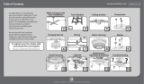
If your fan’s switch housing cap resembles
this one, remove the switch housing
screws using a Phillips head screwdriver.
Then remove the plug button using a
standard screwdriver. Then follow the
TYPE-B ASSEMBLY INSTRUCTIONS on
pages 6-7.
If your fan’s switch housing cap resembles
this one, remove the whole switch
housing by removing the switch housing
assembly screws with a Phillips head
screwdriver.Remove the plug button.
Then follow the TYPE-C ASSEMBLY
INSTRUCTIONS on pages 8-9.
If your fan’s switch housing cap resembles
this one, remove the cap screws with a
Phillips head screwdriver. Then follow the
TYPE-A ASSEMBLY INSTRUCTIONS on
pages 4-5.
Switch
Housing
Cap
Cap
Screw
WHICH ASSEMBLY METHOD WILL I USE?
Switch
Housing
Cap
Switch
Housing
Screw
Switch
Housing
Screw
Switch
Housing
Screw
Plug
Button
Plug
Button
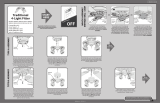
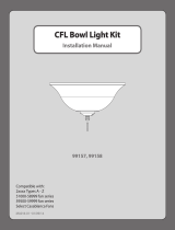
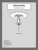
Your light kit is compatible with most ceiling fans. The light kit will attach to the fan’s
switch housing. Begin on page 3 where you will choose the type of switch housing that
most closely resembles the one on your fan. From there, you will be directed to the set of
assembly instructions that are appropriate for installing the light kit to your fan.
Read entire installation instructions carefully before
beginning installation and save these instructions.
BEFORE YOU BEGIN
Switch
Housing
Choose one of the four images below that most closely resembles the switch
housing on your fan; then follow the instructions under the image.
READ AND SAVE THESE INSTRUCTIONS
This product conforms to UL Standard 507.
WARNINGS
w.1 - To reduce the risk of re, electrical shock, or personal injury, mount fan directly from building
structure and/or an outlet box marked acceptable for fan support of 70 lbs (31.8 kg) and use the
mounting screws provided with the outlet box.
w.2 - To avoid possible electrical shock, before installing or servicing your fan, disconnect the power by
turning off the circuit breakers to the outlet box and associated wall switch location. If you cannot lock
the circuit breakers in the off position, securely fasten a prominent warning device, such as a tag, to the
service panel.
c.1 - All wiring must be in accordance with national and local electrical codes ANSI/NFPA 70. If you are
unfamiliar with wiring, use a qualied electrician.
CAUTIONS
If your fan’s switch housing cap resembles
this one, remove the whole switch
housing by removing the switch housing
screws with a Phillips head screwdriver.
Remove the two cap screws from the
inside of the switch housing. Reinstall
the switch housing. Tighten the switch
housing screws.Then follow the TYPE-A
ASSEMBLY INSTRUCTIONS on pages 4-5.