Page is loading ...

Service Manual for Modular Flake
and Nugget Ice Machines
Prodigy Plus A Series Models
NH0422, NS0422, FS0522, NH0622, NS0622, FS0822,
NH0922, NS0922, FS1222, NH1322, NS1322, FS1522

NH0422, NS0422, FS0522, NH0622, NS0622, FS0822, NH0922, NS0922, FS1222, NH1322, NS1322, FS1522
Air, Water or Remote Service Manual
July 2020
Page 2
Introduction
These ice machines are the result of years of
experience with aked and nugget ice machines.
The latest in electronics has been coupled with the
time tested Scotsman aked ice system to provide
reliable ice making and the features needed by
customers.
The features include easily accessible air lters,
simple conductivity water level sensing, evaporator
clearing at shut down, photo-eye sensing bin control
and the ability to add options.
Contents
Installation: ............................................................... Page 4
Location: ................................................................. Page 5
NH0422, NS0422, FS0522, NH0622, NS0622, FS0822 Cabinet Layout ................ Page 6
NH0922, NS0922, FS1222, NH1322, NH1322, FS1522 Cabinet Layout ................ Page 7
Unpacking & Install Prep ..................................................... Page 8
Water .................................................................... Page 9
Electrical- All Models ........................................................ Page 10
Refrigeration - Remote Condenser Models ....................................... Page 12
Remote Condenser Location - Limits ........................................... Page 13
For The Installer: Remote Condenser ........................................... Page 14
Line Set Routing and Brazing (applies to remote units only) ......................... Page 15
Line Set Routing and Brazing ................................................. Page 16
Water - Remote Models ...................................................... Page 17
Final Check List ............................................................ Page 18
Controller ................................................................. Page 19
AutoAlert and Display Code .................................................. Page 20
Component Indicator Lights. . . . . . . . . . . . . . . . . . . . . . . . . . . . . . . . . . . . . . . . . . . . . . . . . . . Page 21
Electrical Component Details ................................................. Page 22
Refrigeration .............................................................. Page 23
Sequence of Operation ...................................................... Page 24
Refrigeration System ........................................................ Page 25
Water System ............................................................. Page 26
Air Cooled Refrigeration ..................................................... Page 27

NH0422, NS0422, FS0522, NH0622, NS0622, FS0822, NH0922, NS0922, FS1222, NH1322, NS1322, FS1522
Air, Water or Remote Service Manual
July 2020
Page 3
Water Cooled Refrigeration ................................................... Page 28
Remote Air Cooled Refrigeration ............................................... Page 29
How Ice Is Made ........................................................... Page 30
Technical Information. . . . . . . . . . . . . . . . . . . . . . . . . . . . . . . . . . . . . . . . . . . . . . . . . . . . . . . . Page 31
Heat Load, Charge and Condenser GPM ........................................ Page 32
Refrigeration System Pressures ............................................... Page 33
Maintenance .............................................................. Page 34
Maintenance: Scale Removal and Sanitation ..................................... Page 35
Maintenance: Sensors ....................................................... Page 36
Service Diagnosis - Air Cooled ................................................ Page 37
Service Diagnosis - Water Cooled .............................................. Page 38
Service Diagnosis - Remote Air Cooled ......................................... Page 39
Service Diagnosis - Remote Air Cooled ......................................... Page 40
Service Diagnosis - Refrigeration System Failure .................................. Page 41
Service Diagnosis - Optional Ice Level Controls ................................... Page 42
Options .................................................................. Page 43
Repair Procedures: Bearing And Extruder ....................................... Page 44
Auger and Evaporator Inspection .............................................. Page 45
Water Seal ................................................................ Page 46
Repair Procedures: The Gear Reducer .......................................... Page 47
Repair Procedures: Replace the Evaporator ...................................... Page 48

NH0422, NS0422, FS0522, NH0622, NS0622, FS0822, NH0922, NS0922, FS1222, NH1322, NS1322, FS1522
Air, Water or Remote Service Manual
July 2020
Page 4
Installation:
This machine is designed to be used indoors, in a
controlled environment. Operation outside the limits
listed here will void the warranty.
Air temperature limits
Minimum Maximum
Ice maker 50
o
F. / 10
o
C. 100
o
F. / 38
o
C.
Remote
condenser
-20
o
F. / -28
o
C. 120
o
F. / 48
o
C.
Water temperature limits
Minimum Maximum
All models 40
o
F. / 4.4
o
C. 100
o
F. / 38
o
C.
Water pressure limits (potable)
Minimum Maximum
All models 20 psi / 1.3 bar 80 psi / 5.5 bar
Water pressure limit to water cooled condenser is 150
PSI
Voltage limits
Minimum Maximum
115 volt 104 126
208-230 60 Hz 198 253
Minimum conductivity (RO water)
• 10 microSiemens / CM
Water Quality (ice making circuit)
• Potable
The quality of the water supplied to the ice machine
will have an impact on the time between cleanings
and ultimately on the life of the product. Water can
contain impurities either in suspension or in solution.
Suspended solids can be ltered out. In solution
or dissolved solids cannot be ltered, they must be
diluted or treated. Water lters are recommended
to remove suspended solids. Some lters have
treatment in them for dissolved solids.
Check with a water treatment service for a
recommendation.
RO water. This machine can be supplied with Reverse
Osmosis water, but the water conductivity must be no
less than 10 microSiemens/cm.
Potential for Airborne Contamination
Installing an ice machine near a source of yeast
or similar material can result in the need for more
frequent sanitation cleanings due to the tendency of
these materials to contaminate the machine.
Most water lters remove chlorine from the water
supply to the machine which contributes to this
situation. Testing has shown that using a lter that
does not remove chlorine, such as the Scotsman
Aqua Patrol, will greatly improve this situation.
Warranty Information
The warranty statement for this product is provided
separately from this manual. Refer to it for applicable
coverage. In general warranty covers defects
in material or workmanship. It does not cover
maintenance, corrections to installations, or situations
when the machine is operated in circumstances that
exceed the limitations printed above.

NH0422, NS0422, FS0522, NH0622, NS0622, FS0822, NH0922, NS0922, FS1222, NH1322, NS1322, FS1522
Air, Water or Remote Service Manual
July 2020
Page 5
Location:
While the machine will operate satisfactorily within the
listed air and water temperature limits, it will produce
more ice when those temperatures are nearer the
lower limits. Avoid locations that are hot, dusty, greasy
or conned. Air cooled models need plenty of room
air to breathe. Air cooled models must have at least
six inches of space at the back for air discharge;
however, more space will allow better performance.
Airow
Air ows into the front of the cabinet and out the back.
The air lters are on the outside of the front panel and
are easily removed for cleaning.
Options
Side air ow kits KPFSA223 or KPFSA227 are
available for air cooled models. A lter kit for the
remote condenser is KERCF
Ice is made until it lls the bin enough to block an
infrared light beam inside the base of the machine. A
eld installed kit is available to adjust the maintained
ice level lower. The kit number is KVS.
The standard controller has excellent diagnostic
capabilities and communicates to the user through the
AutoAlert light panel, seen through the front panel.
Field installed kits are available that can log data and
provide additional information when the front panel is
removed. The kit numbers are KSBU and KSB-NU.
See page 21.
Bin compatibility
All models have the same footprint: 22 inches wide
by 24 inches deep. Conrm available space when
replacing a prior model.
Bin & adapter list:
• B322S – no adapter needed
• B330P or B530P or B530S – Use KBT27
• B842S – KBT39
• B948S – KBT38 for single unit
• B948S – KBT38-2X for two units side by side
• BH1100, BH1300 and BH1600 upright bins include
ller panels to accommodate a single 22 inch wide
ice machine. No adapter is needed.
Dispenser compatibility
Only nugget ice models may be used with ice
dispensers. Flaked ice is not dispensable.
• ID150 – use KBT42 and KDIL-PN-150, includes
KVS, KNUGDIV and R629088514
• ID200 – use KBT43 and KNUGDIV and KVS
• ID250 – use KBT43 and KNUGDIV and KVS
See sales literature for other brand model ice and
beverage dispenser applications.
Other Bins & Applications:
Note the drop zone and ultrasonic sensor locations in
the illustrations on the next pages.
Scotsman ice systems are designed and
manufactured with the highest regard for safety
and performance. Scotsman assumes no liability of
responsibility of any kind for products manufactured
by Scotsman that have been altered in any way,
including the use of any part and/or other components
not specically approved by Scotsman.
Scotsman reserves the right to make design changes
and/or improvements at any time. Specications and
design are subject to change without notice.

NH0422, NS0422, FS0522, NH0622, NS0622, FS0822, NH0922, NS0922, FS1222, NH1322, NS1322, FS1522
Air, Water or Remote Service Manual
July 2020
Page 6
NH0422, NS0422, FS0522, NH0622, NS0622, FS0822 Cabinet Layout
ICE DROP
OPENING
REMOTE COOLED
BACK VIEW
WATER COOLED
BACK VIEW
AIR COOLED
BACK VIEW
LEFT SIDE VIEW
FRONT VIEW
57.7
22.70
58.4
23.00
55.9
22.00
LOUVER AND
REMOVABLE FILTER
A/C UNITS ONLY
61
24.00
2.3
.90
4
1.59
5.5
2.17
4.7
1.85
23.1
9.1
37.2
14.65
3/4" FPT
DRAIN
.88 DIA.
ELECTRICAL
ACCESS
3/8" FLARE
MACHINE
WATER
INLET
61
24.00
REF.
41.9
16.50
31.8
12.50
55.9
22.00 REF.
10.9
4.30
16.5
6.48
7.1
2.81
7.4
2.92
PLAN VIEW
23.1
9.1
4
1.59
5.5
2.17
4.7
1.85
37.1
14.60
8.6
3.38
39.2
15.45
44.6
17.55
49.1
19.31
3/8" FPT
CONDENSER
WATER
INLET
.88 DIA.
ELECTRICAL
CONNECTION
3/8" FLARE
MACHINE
WATER
INLET
3/4" FPT
DRAIN
1/2" FPT
CONDENSER
DRAIN
23.1
9.1
4.7
1.85
37.1
14.60
4
1.59
5.5
2.17
17.2
6.78
23.6
9.28
48.9
19.24
REMOTE COND.
LIQUID LINE
3/8" COPPER
BRAZE JOINT.
REMOTE COND.
DISCHARGE LINE
1/2" COPPER
BRAZE JOINT
.88 DIA.
ELECTRICAL
CONNECTION
3/4" FPT
DRAIN
3/8" FLARE
MACHINE
WATER
INLET

NH0422, NS0422, FS0522, NH0622, NS0622, FS0822, NH0922, NS0922, FS1222, NH1322, NS1322, FS1522
Air, Water or Remote Service Manual
July 2020
Page 7
NH0922, NS0922, FS1222, NH1322, NH1322, FS1522 Cabinet Layout
ICE DROP
OPENING
PLAN VIEW
REMOTE COOLED
BACK VIEW
WATER COOLED
BACK VIEW
AIR COOLED
BACK VIEW
LEFT SIDE VIEW
FRONT VIEW
55.9
22.00
68.6
27.00
57.7
22.70
LOUVER AND
REMOVABLE FILTER
A/C UNITS ONLY
61
24.00
30.7
12.10
4
1.59
4.7
1.85
47.4
18.65
3/4" FPT
DRAIN
3/8" FLARE
MACHINE
WATER
INLET
.88 DIA.
ELECTRICAL
ACCESS
61
24.00
REF.
55.9
22.00
REF.
31.8
12.50
10.9
4.30
16.5
6.48
7.4
2.92
7.1
2.81
ULTRA SONIC
BIN LEVEL
SENSOR
OPTIONAL
4
1.59
5.5
2.17
32
12.59
38.3
15.09
30.7
12.10
4.7
1.85
47.2
18.60
53.9
21.24
REMOTE COND.
DISCHARGE LINE
1/2" COPPER
BRAZE JOINT
REMOTE COND.
LIQUID LINE
3/8" COPPER
BRAZE JOINT.
.88 DIA.
ELECTRICAL
CONNECTION
3/8" FLARE
MACHINE
WATER
INLET
4
1.59
48.3
19.00
44.6
17.56
5.5
2.17
30.7
12.10
12.6
4.95
39.2
15.45
4.7
1.85
47.2
18.60
3/8" FPT
CONDENSER
WATER
INLET
1/2" FPT
CONDENSER
DRAIN
3/8" FLARE
MACHINE
WATER
INLET
.88 DIA.
ELECTRICAL
CONNECTION
3/4" FPT
DRAIN

NH0422, NS0422, FS0522, NH0622, NS0622, FS0822, NH0922, NS0922, FS1222, NH1322, NS1322, FS1522
Air, Water or Remote Service Manual
July 2020
Page 8
Place on Bin or Dispenser
If reusing an existing bin, be sure that the bin is
in good shape and that the gasket tape on the
top is not torn up. Water leaks, not covered by
warranty, could result from a poor sealing surface. If
installing a remote or a remote low side, a new bin
is recommended due to the high cost to the user of
replacing an old bin when a remote system is on top.
Install the correct adapter, following the directions
supplied with that adapter.
Hoist the machine onto the adapter.
Note: The machine is heavy! Use of a mechanical lift
is recommended.
Position the machine on the bin or adapter. Secure
with straps from the hardware bag packed with the
machine, or those supplied with the adapter.
Remove any plastic covering the stainless steel
panels.
Note: The standard machine set up includes visible
on and o switches. Those can be covered up by
changing the bezel in the front panel’s trim strip. A
cover-up bezel is included with the hardware bag.
Remove any packaging, such as tape or foam blocks,
that may be near the gear reducer or ice chute.
Level the bin and ice machine front to back and left to
right by using the bin leg levelers.
Unpacking & Install Prep
Panel Removal
1. Locate and loosen the two screws at the bottom of
the front panel.
2. Pull the front panel out at the bottom until it clears.
3. Lower the front panel down and o the machine.
4. Remove two screws at the front of the top panel.
Lift up the front of the top panel, push the top panel
back an inch, then lift to remove.
5. Locate and loosen the screw holding each side
panel to the base. Left side panel also has a screw
holding it to the control box.
6. Pull the side panel forward to release it from the
back panel.

NH0422, NS0422, FS0522, NH0622, NS0622, FS0822, NH0922, NS0922, FS1222, NH1322, NS1322, FS1522
Air, Water or Remote Service Manual
July 2020
Page 9
The water supply for ice making must be cold, potable
water. There is a single 3/8” male are potable water
connection on the back panel. Water cooled models
also have a 3/8” FPT inlet connection for the water
cooled condenser. Chilled water can also be used for
this connection.
Drain
There is one ¾” FPT condensate drain tting at the
back of the cabinet. Water cooled models also have a
½” FPT discharge drain connection on the back panel.
Tubing
Connect the potable water supply to the potable water
tting, 3/8” OD copper tubing or the equivalent is
recommended.
Water ltration is recommended. If there is an existing
lter, change the cartridge.
Connect the water cooled water supply to the
condenser inlet.
Note: Do NOT lter water to the water cooled
condenser circuit.
Connect the drain tube to the condensate drain tting.
Connect the water cooled condenser drain tube to the
condenser outlet.
Do not Tee ice machine drains into the drain tube
from the ice storage bin or dispenser. Back ups
could contaminate and / or melt the ice in the bin or
dispenser.
Follow all local and national codes for tubing, traps
and air gaps.
Water
Water Inlet
Connection
Drain
Connection
Condensate
Drain Tube
Building Drain
Water Inlet
Connection
Drain
Connection
Condensate
Drain Tube
Condenser Inlet
Connection
Condenser
Drain Tube
Air Cooled or Remote Plumbing
Water Cooled Plumbing

NH0422, NS0422, FS0522, NH0622, NS0622, FS0822, NH0922, NS0922, FS1222, NH1322, NS1322, FS1522
Air, Water or Remote Service Manual
July 2020
Page 10
The machine does not include a power cord, one
must be eld supplied or the machine hard wired to
the electrical power supply. The junction box for the
electrical connection is on the back panel.
Refer to the dataplate on the machine for minimum
circuit ampacity and determine the proper wire size
for the application. The dataplate (on the back of the
cabinet) also includes the maximum fuse size.
Electrical- All Models
Electrical power is connected to wires inside the
junction box in the back of the cabinet. Use a strain
relief and connect a ground wire to the ground screw.
Do not use an extension cord.
Follow all local and national codes.
Model Series Dimensions
w” x d” x h”
Voltage
Volts/Hz/Phase
Condenser
Type
Min Circuit
Ampacity
Max Fuse Size or HACR
Type Circuit Breaker
NH0422A-1 A 22 x 24 x 23 115/60/1 Air 12.9 15
NH0422W-1 A 22 x 24 x 23 115/60/1 Water 12.1 15
NS0422A-1 A 22 x 24 x 23 115/60/1 Air 12.9 15
NS0422W-1 A 22 x 24 x 23 115/60/1 Water 12.1 15
FS0522A-1 A 22 x 24 x 23 115/60/1 Air 12.9 15
FS0522W-1 A 22 x 24 x 23 115/60/1 Water 12.1 15
NH0622A-1 A 22 x 24 x 23 115/60/1 Air 16.0 20
NH0622W-1 A 22 x 24 x 23 115/60/1 Water 14.4 20
NH0622R-1 A 22 x 24 x 23 115/60/1 Remote 17.1 20
NS0622A-1 A 22 x 24 x 23 115/60/1 Air 16.0 20
NS0622W-1 A 22 x 24 x 23 115/60/1 Water 14.4 20
NS0622R-1 A 22 x 24 x 23 115/60/1 Remote 17.1 20
FS0822A-1 A 22 x 24 x 23 115/60/1 Air 16.0 20
FS0822W-1 A 22 x 24 x 23 115/60/1 Water 14.4 20
FS0822R-1 A 22 x 24 x 23 115/60/1 Remote 17.1 20
NH0622A-32 A 22 x 24 x 23 208-230/60/1 Air 8.8 15
NS0622A-32 A 22 x 24 x 23 208-230/60/1 Air 8.8 15
FS0822W-32 A 22 x 24 x 23 208-230/60/1 Water 7.6 15
NS0622A-6 A 22 x 24 x 23 230/50/1 Air 7.9 15
Table continued on following page

NH0422, NS0422, FS0522, NH0622, NS0622, FS0822, NH0922, NS0922, FS1222, NH1322, NS1322, FS1522
Air, Water or Remote Service Manual
July 2020
Page 11
Electrical- All Models
Model Series Dimensions
w” x d” x h”
Voltage Volts/
Hz/Phase
Condenser
Type
Min Circuit
Ampacity
Max Fuse Size or HACR
Type Circuit Breaker
NH0922A-1 A 22 x 24 x 27 115/60/1 Air 24.0 30
NH0922R-1 A 22 x 24 x 27 115/60/1 Remote 25.0 30
NS0922A-1 A 22 x 24 x 27 115/60/1 Air 24.0 30
NS0922R-1 A 22 x 24 x 27 115/60/1 Remote 25.0 30
NH0922A-32 A 22 x 24 x 27 208-230/60/1 Air 11.9 15
NH0922W-32 A 22 x 24 x 27 208-230/60/1 Water 10.7 15
NH0922R-32 A 22 x 24 x 27 208-230/60/1 Remote 11.7 15
NS0922A-32 A 22 x 24 x 27 208-230/60/1 Air 11.9 15
NS0922W-32 A 22 x 24 x 27 208-230/60/1 Water 10.7 15
NS0922R-32 A 22 x 24 x 27 208-230/60/1 Remote 11.7 15
FS1222A-32 A 22 x 24 x 27 208-230/60/1 Air 11.9 15
FS1222W-32 A 22 x 24 x 27 208-230/60/1 Water 10.7 15
FS1222R-32 A 22 x 24 x 27 208-230/60/1 Remote 11.7 15
NS0922W-3 A 22 x 24 x 27 208-230/60/3 Water 8.0 15
FS1222A-3 A 22 x 24 x 27 208-230/60/3 Air 9.2 15
FS1222R-3 A 22 x 24 x 27 208-230/60/3 Remote 9.0 15
NH1322A-32 A 22 x 24 x 27 208-230/60/1 Air 17.8 20
NH1322W-32 A 22 x 24 x 27 208-230/60/1 Water 16.6 20
NH1322R-32 A 22 x 24 x 27 208-230/60/1 Remote 17.6 20
NS1322A-32 A 22 x 24 x 27 208-230/60/1 Air 17.8 20
NS1322W-32 A 22 x 24 x 27 208-230/60/1 Water 16.6 20
NS1322R-32 A 22 x 24 x 27 208-230/60/1 Remote 17.6 20
FS1522A-32 A 22 x 24 x 27 208-230/60/1 Air 17.8 20
FS1522R-32 A 22 x 24 x 27 208-230/60/1 Air 17.6 20
NS1322W-3 A 22 x 24 x 27 208-230/60/3 Water 9.9 15
NH1322W-3 A 22 x 24 x 27 208-230/60/3 Water 9.9 15

NH0422, NS0422, FS0522, NH0622, NS0622, FS0822, NH0922, NS0922, FS1222, NH1322, NS1322, FS1522
Air, Water or Remote Service Manual
July 2020
Page 12
Refrigeration - Remote Condenser Models
Remote condenser models have additional installation
needs.
The correct remote condenser fan and coil must
be connected to the ice making head. Liquid and
discharge tubing connections are on the back of
the ice machine cabinet. Tubing kits are available in
several lengths to accommodate most installations.
Order the one that just exceeds the length needed for
the installation.
The kit numbers are:
BRTE10, BRTE25, BRTE40, BRTE75
There are limits as to how far away from the ice
machine and where the remote condenser can be
located. See page 10 for those limits.
The correct condenser must be used:
Ice Machine
Model
Voltage Condenser
Model
NH0622R-1
NS0622R-1
FS0822R-1
NH0922R-1
NS0922R-1
115 ERC111-1
NH0922R-32
NS0922R-32
FS1222R-32
FS1222R-3
208-230 ERC311-32
NH1322R-32
NS1322R-32
208-230 ERC311-32
Do not reuse condenser coils contaminated with
mineral oil (used with R-502 for example). They will
cause compressor failure and will void the warranty.
A headmaster is required for all remote condenser
systems. Installation of headmaster kit KPFHM will be
required if any of the following condensers are being
used:
ERC101-1, ERC151-32, ERC201-32, ERC301-32,
ERC402-32
Use of non-Scotsman condensers requires
pre-approval from Scotsman Engineering.
Ground
Wire
Connection
Black
White
Ground
Power
Supply
Wires
Install
Strain
Relief
Junction
Box
Cover
To Remote
Condenser
Fan Motor
Blue
Ground
Wire
Connection
Black
White
Ground
Power
Supply
Wires
Install
Strain
Relief
Install
Strain
Relief
Junction
Box
Cover

NH0422, NS0422, FS0522, NH0622, NS0622, FS0822, NH0922, NS0922, FS1222, NH1322, NS1322, FS1522
Air, Water or Remote Service Manual
July 2020
Page 13
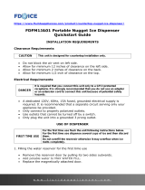
Remote Condenser Location - Limits
Use the following for planning the placement of the
condenser relative to the ice machine
Location Limits - condenser location must not exceed
ANY of the following limits:
• Maximum rise from the ice machine to the
condenser is 35 physical feet
• Maximum drop from the ice machine to the
condenser is 15 physical feet
• Physical line set maximum length is 100 feet.
• Calculated line set length maximum is 150.
Calculation Formula:
• Drop = dd x 6.6 (dd = distance in feet)
• Rise = rd x 1.7 (rd = distance in feet)
• Horizontal Run = hd x 1 (hd = distance in feet)
• Calculation: Drop(s) + Rise(s) + Horizontal
• Run = dd+rd+hd = Calculated Line Length
Congurations that do NOT meet these requirements
must receive prior written authorization from
Scotsman to maintain warranty.
Do NOT:
• Route a line set that rises, then falls, then rises.
• Route a line set that falls, then rises, then falls.
Calculation Example 1:
The condenser is to be located 5 feet below the ice
machine and then 20 feet away horizontally.
5 feet x 6.6 = 33. 33 + 20 = 53. This location would be
acceptable
Calculation Example 2:
The condenser is to be located 35 feet above and
then 100 feet away horizontally. 35 x 1.7 = 59.5.
59.5 +100 = 159.5. 159.5 is greater than the 150
maximum and is NOT acceptable.
Operating a machine with an unacceptable
conguration is misuse and will void the warranty.
22.87"
17.15"
40.35"
rd Max 35 feet
dd Max 15 feet
hd
Remote Condenser located
above ice machine.
Remote Condenser located
below ice machine.
Condenser Distance &
Location Schematic

NH0422, NS0422, FS0522, NH0622, NS0622, FS0822, NH0922, NS0922, FS1222, NH1322, NS1322, FS1522
Air, Water or Remote Service Manual
July 2020
Page 14
For The Installer: Remote Condenser
Locate the condenser as near as possible to the
interior location of the ice machine. Allow it plenty of
space for air and cleaning: keep it a minimum of two
feet away from a wall or other rooftop unit.
Note: The location of the condenser relative to the ice
machine is LIMITED by the specication on the prior
page.
Roof penetration. In many cases a roong contractor
will need to make and seal the hole in the roof for the
line sets. The suggested hole diameter is 2 inches.
Meet all applicable building codes.
Roof Attachment
Install and attach the remote condenser to the roof
of the building, using the methods and practices of
construction that conform to the local building codes,
including having a roong contractor secure the
condenser to the roof
Power Supply from
Ice Machine
Remote Condenser
To Remote Condenser
Refrigeration
connections
Brazing required
Refrigeration
Tubing

NH0422, NS0422, FS0522, NH0622, NS0622, FS0822, NH0922, NS0922, FS1222, NH1322, NS1322, FS1522
Air, Water or Remote Service Manual
July 2020
Page 15
To Remote
Condenser
Fan Motor
Power Supply to Condenser
Refrigeration Tubing
Potable Water
Supply
Condensate Drain
Line Set Routing and Brazing (applies to remote units only)
Do not connect the refrigeration tubing until all routing
and forming of the tubing is complete. See the
Coupling Instructions for nal connections.
1. Each set of tubing lines contains a 3/8” diameter
liquid line, and a 1/2” diameter discharge line.
Both ends of each line are designed for eld
brazed connections.
Note: The openings in the building ceiling or wall,
listed in the next step, are the minimum sizes
recommended for passing the refrigerant lines
through.
2. Have the roong contractor cut a minimum hole
for the refrigerant lines of 2”. Check local codes,
a separate hole may be required for the electrical
power supply to the condenser.
Caution: Do NOT kink the refrigerant tubing while
routing it.
3. Route the refrigerant tubes thru the roof opening.
Follow straight line routing whenever possible.
Excess tubing must be cut to proper length prior to
connecting to the ice maker and condenser.
4. The tubing must be evacuated after connection
to the ice maker or condenser before opening the
ball valve.
5. Have the roong contractor seal the holes in the
roof per local codes

NH0422, NS0422, FS0522, NH0622, NS0622, FS0822, NH0922, NS0922, FS1222, NH1322, NS1322, FS1522
Air, Water or Remote Service Manual
July 2020
Page 16
Line Set Routing and Brazing
Do not connect the refrigerant tubing until all
routing and forming of the tubing is complete.
Final connections requires brazing, steps must
be performed by an EPA certied type II or higher
technician.
The Lineset of tubing contains a 3/8” diameter liquid
line, and a 1/2” diameter discharge line.
Note: The openings in the building ceiling or wall,
listed in the next step, are the minimum sizes
recommended for passing the refrigerant lines
through.
Have the roong contractor cut a minimum hole for
the refrigerant lines of 1 3/4”. Check local codes,
a separate hole may be required for the electrical
power supply to the condenser.
Caution: Do NOT kink the refrigerant tubing while
routing it.
At Condenser:
1. Remove protective plugs from both connections
and vent the nitrogen from the condenser.
2. Remove the tubing access bracket to allow more
room for brazing.
3. Route the lineset tubes to there connection.
4. Clean tubing ends and position into stubs.
Note: Be sure tube and stubs are round, dress with
swage tool if needed.
At Head:
1. Remove the tubing access bracket to allow
more room for brazing.
2. Conrm connection ball valves are fully
closed.
3. Remove protective plugs from both connec-
tions.
4. Remove caps from access valve connec-
tions.
5. Remove cores from access valves.
6. Connect refrigeration hoses to access
valves.
7. Connect dry nitrogen source to liquid line
connection.
8. Shorten tubing to correct length, clean ends
and insert them into valve stubs.
Note: Be sure tube and stubs are round, dress with
swage tool if needed.
9. Add heat sink material to ball valve body.
10. Open nitrogen and ow 1 psi nitrogen into
liquid line tube and braze the liquid line and
suction line tubes to the valve stubs.
11. With nitrogen owing braze the liquid and
suction line connections.
At Condenser:
1. Braze the liquid and suction line connections.
At Head:
1. Remove nitrogen source.
2. Return valve cores to access valves.
3. Connect vacuum pump to both access
valves and evacuate the tubing and head to
at least a 300 micron level.
4. Remove vacuum pump and add R-404A to
all three tubes to provide a positive pressure.
5. Leak check the all braze connections and
repair any leaks.
6. Open both valves to full open.
Note: The full refrigerant charge is contained in the
receiver of the ice machine.

NH0422, NS0422, FS0522, NH0622, NS0622, FS0822, NH0922, NS0922, FS1222, NH1322, NS1322, FS1522
Air, Water or Remote Service Manual
July 2020
Page 17
Water - Remote Models
The water supply for ice making must be cold, potable
water. There is a single 3/8” male are potable water
connection on the back panel.
Backow
The design of the oat valve and reservoir prevents
potable water backow by means of a 1" air gap
between the reservoir's maximum water level and the
oat valve water inlet orice.
Drain
There is one 3/4” FPT condensate drain tting at the
back of the cabinet.
Attach Tubing
1. Connect the potable water supply to the potable
water tting, 3/8” OD copper tubing or the
equivalent is recommended.
2. Change the cartridge on the existing water lter (if
any present).
3. Connect the drain tube to the condensate drain
tting. Use rigid tubing.
4. Vent the drain tubing between the ice machine
and the building drain.
Do not Tee ice machine drains into the drain tube
from the ice storage bin or dispenser. Back ups
could contaminate and/or melt the ice in the bin or
dispenser. Be sure to vent the bin drain.
Follow all local and national codes for tubing, traps
and air gaps.
To Remote Condenser
Potable Water
Connection
Drain Vent
Condensate Drain

NH0422, NS0422, FS0522, NH0622, NS0622, FS0822, NH0922, NS0922, FS1222, NH1322, NS1322, FS1522
Air, Water or Remote Service Manual
July 2020
Page 18
Power
Status
No Water
Time to Clean
On
O
Final Check List
After connections:
1. Wash out the bin. If desired, the interior of the bin
could be sanitized.
2. Locate the ice scoop (if supplied) and have it
available for use when needed.
3. Remote only: Switch on the electrical power to
warm up the compressor. Do not start the machine
for 4 hours.
Final Check List:
1. Is the unit located indoors in a controlled
environment?
2. Is the unit located where it can receive adequate
cooling air?
3. Has the correct electrical power been supplied to
the machine?
4. Have all the water supply connections been
made?
5. Have all the drain connections been made?
6. Has the unit been leveled?
7. Have all unpacking materials and tape been
removed?
8. Has the protective covering on the exterior panels
been removed?
9. Is the water pressure adequate?
10. Have the drain connections been checked for
leaks?
11. Has the bin interior been wiped clean or sanitized?
12. Have any water lter cartridges been replaced?
13. Have all required kits and adapters been properly
installed?
Control and Machine Operation
Once started, the ice machine will automatically make
ice until the bin or dispenser is full of ice. When ice
level drops, the ice machine will resume making ice.
Caution: Do not place anything on top of the ice
machine, including the ice scoop. Debris and moisture
from objects on top of the machine can work their way
into the cabinet and cause serious damage. Damage
caused by foreign material is not covered by warranty.
There are four indicator lights at the front of the
machine that provide information on the condition
of the machine: Power, Status, Water, De-scale &
Sanitize.
Note: If the De-Scale & Sanitize light is ON, following
the cleaning process will clear the light for another
cleaning time internal.
Two button switches are at the front – On and O. To
switch the machine OFF, push and release the O
button. The machine will shut o at the end of the next
cycle. To switch the machine ON, push and release
the On button. The machine will go through a start up
process and then resume ice making.
Lower Light and Switch Panel
This user accessible panel provides important
operational information and duplicates the lights and
switches on the controller. It also allows access to the
On and O buttons that operate the ice machine.
Sometimes access to the switches should be limited
to prevent unauthorized operation. For that purpose a
xed panel is shipped in the hardware package. The
xed panel cannot be opened.
To install the xed panel:
1. Remove the front panel and remove the bezel.
2. Spread the bezel frame open and remove original
door, insert xed panel into bezel. Be sure it is in
the closed position.
3. Return bezel to panel and install panel on unit.

NH0422, NS0422, FS0522, NH0622, NS0622, FS0822, NH0922, NS0922, FS1222, NH1322, NS1322, FS1522
Air, Water or Remote Service Manual
July 2020
Page 19
Controller
Clean
Code
Display
Component Operation Indicator Lights
Code Description
. . . . . . . . Freeze Mode
flashes . . Freeze Mode is Pending
.... ....Bin is Full
.... ....Clean Cycle
.... ....Board Locked
.... ....Test Mode
.... ....Off
.... ....Self Test Failed
flashes. . No ice sensed - Retrying
..... ....No ice sensed - Shut Down
flashes . Auger motor high load - Retrying
. . . . . . . . Auger motor high load - Shut Down
. . . . . . . . No water in reservoir
. . . . . . . . Refrigeration pressure too high / low
- Unit Remotely
Locked Out - Contact Leasing Company
F
F
b
C
L
d
O
E
1
1
2
2
3
4
All 4 Upper Lights Flashing
Control Operation - See Manual
Water Light On
De-Scale Light On
Test Mode
Recall Diagnostic Codes
Clear Diagnostic Codes
Reset from Code 1, 2, 3 or 4
- Restore water supply to
machine.
- Clean and sanitize
machine.
- Depress Off for 3 seconds,
then depress Clean for 3 seconds.
- Depress Off
for 3 seconds. Press Clean repeatedly to
go from most recent to oldest of 10.
- Switch unit off,
depress and hold Clean and Off for 3
seconds.
- Depress
Off then Depress On.
Technician Section
02-4407-01
On Off
Power Status De-scaleWater
Sanitize
Location of Optional
Vari-Smart (KVS)
Location of Optional
Smart-Board

NH0422, NS0422, FS0522, NH0622, NS0622, FS0822, NH0922, NS0922, FS1222, NH1322, NS1322, FS1522
Air, Water or Remote Service Manual
July 2020
Page 20
The controller uses indicator lights to provide the user
with information on Power, Status, Water or Time to
Clean. These are known as the AutoAlert panel.
Additionally a 7 segment display is under the front
panel. It shows operational status or problem codes.
The Power light is on Green anytime the machine is
supplied with electrical power.
The Status light is on Green when the machine has
been switched to the ice making mode. It will also
blink green if the unit has been equipped with an
optional Smart-Board AND the Smart-Board has
detected potential malfunction.
The Water light will blink Red if the water sensor does
not detect water.
The De-Scale / Sanitize light will glow Yellow when
the time to clean timer has reached its set time since
the last cleaning. It also blinks during the rst part of
the cleaning mode
AutoAlert and Display Code
Code Description
. . . . . . . . Freeze Mode
ashes . . Freeze Mode is Pending
. . . . . . . . Bin is Full
. . . . . . . . Clean Cycle
. . . . . . . . Board Locked
. . . . . . . . Test Mode
. . . . . . . . O
. . . . . . . . Self Test Failed
ashes. . No ice sensed - Retrying
. . . . . . . . . No ice sensed - Shut Down
ashes . Auger motor high load - Retrying
. . . . . . . . Auger motor high load - Shut Down
. . . . . . . . No water in reservoir
. . . . . . . . Refrigeration pressure too high / low
/