
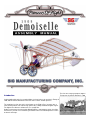
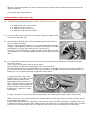
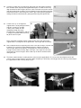
Introduction
The first man-
carrying aeroplane flight in
Europe was by Santos-Dumont in 1906
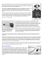
Credited with making the first recorded flight of a heavier-than-
air machine in Europe in
1906, Alberto Santos-Dumont became one of the earliest aviation pioneers.
The aeroplane he flew, the 14-bis (also known as the "Bird of Prey" to some) was a
canard configuration of his own design powered by a 50hp Antoinette dirigible engine.
The flight went a distance of 50 meters in a straight line.
Hardly a performance that rivaled the Wright Brothers contemporary efforts, the flight
none-the-less stirred a true awakening of aviation interest and development in France
and much of Europe.

.
Well-educated, Santos-Dumont possessed a scientific mind and was wealthy enough to pursue his
dreams of powered flight. He realized early on that if he could design and build a machine that was
light enough to take advantage of the minimal power offered by engines of the day, he might be
able to achieve greater success with true controlled flight.
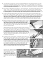
Late in 1907, he completed and flew the world’s first true "ultra" light airplane. It had a 16-1/2 foot
wingspan and was powered by a 20hp Dutheil
-Chalmers motor, swinging a huge wooden
propeller. The airplane was constructed almost entirely of bamboo and was of an unusual
configuration. The pilot sat at the front of its open triangular fuselage, less than one foot off the
ground.
It was an incredibly frail airplane but this very lightness and lack of mass were likely contributing
reasons to the fact that no pilot ever met with a fatal accident while flying it, or its future versions.
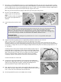
Named the "Demoiselle" (French for "little lady"), the design continued to be improved and built in
reasonable numbers, powered by a variety of powerplants, up to and including a V-8 Antoinette
engine, nestled between the pilot’s legs, turning an eight foot chain to drive the prop!
Now, there is a true leap of faith!
The diminutive Demoiselle weighed
only 315 lbs.- approximately half
the weight of the Wright Brothers
1903 Flyer!
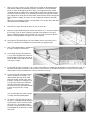
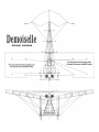
The SIG Demoiselle represents a reasonable semi-scale rendition of Santos-
Dumont’s Model 20 version of the Demoiselle. Of special interest is the fully
articulated tail group that controls pitch and yaw in exactly the same manner as the
full-scale version. This simple universal joint is easy to make and allows full control
movement of the tail group for amazingly smooth and positive control. We’ve
comfortably flown the Demoiselle in spaces as small as one half of a typical
basketball court, with full control authority. We’ve found that altitude is easily
controlled with throttle, saving elevator input primarily for turns, landings, and take-
offs.
Using the radio equipment, battery pack, GWS motor, and propeller recommended
in these instructions, you'll find the flight speed of this airplane to be incredibly slow
and scale-like! Our prototypes have flown hundreds of flights, (both indoors and
outdoors), and continue to fly very well to this day. They never fail to draw "oohs"
and "aahs" from on-lookers.
The Demoiselle can be flown outdoors but only in very light to no-wind conditions. Its light weight and low wing loading do not
lend themselves to windy conditions. In fairness, Santos-Dumont had precisely the same issues to deal with in his full-size
counterparts.
Building your own SIG Demoiselle has been made much easier with the supplied laser-
cut parts. The included profile "pilot" has
been used in all of our Demoiselle models, lending a great look to this otherwise austere scale model. Detailing your Demoiselle
is covered in these instructions and primarily consists of adding the non-functional rigging wires, a little paint and assembling
and mounting the molded plastic 2-cylinder engine. If you’re anything like us, you’ll find that the more details you add to your
Demoiselle, the more you want to do! Between flying sessions, you may enjoy displaying this intriguing and unusual airplane in
your workshop, den, or office
-
it never fails to fascinate!
This kit is not intended for beginning modelers. However, most intermediate modelers with average building skills will find this kit
easy to build and fly. These instructions assume that you are aware of the importance of using the correct type and amount of
glue, how to make proper wood joints, and how to fly R/C models.
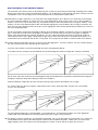
Motors And Propellers
We’ve chosen the well-proven GWS "R/C Indoor Power System" motors and gear
drives to power the SIG Demoiselle (note that Maxx Products also markets these
exact same power units under their "MPI" name). These motor and gear drive
systems are very easy to use, widely available, very inexpensive, and are of good
quality. These systems are currently available in eight different gear ratios, capable
of swinging propellers from 6" diameter all the way up to 12" diameter. GWS also
produces a good selection of propellers to fit all of their gear drive systems. During
the development of the Demoiselle, we experimented with different gear ratios and
propellers.

.
We found that a very good combination for this airplane was the GWS "DX-B" system (same as Maxx Products "EPU-
7"), which
has a 7:1 gear ratio, along with the GWS 10"x5" propeller. With a 7-cell 350mAh Ni-Cad battery pack (Sanyo P/N N-350AAC),
this combination has provided good power margins, scale
-
like speeds along with very good flight duration.
Radio Equipment, Speed Controller, Batttery Pack, And Connectors
One of the very reasons that indoor models such as the Demoiselle are now possible is the fairly recent availability of good
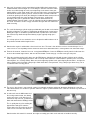
quality, reasonably priced light-weight micro receivers, servos, and speed controllers (ESC’s). Up to this time, such equipment
was only available from small, highly specialized sources at relatively high prices.
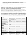
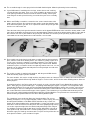
Here are the airborne system components we’ve used in the Demoiselle.
ITEM WEIGHT
Maxx Products (MPI) #MX-6800 Pico 4-Ch Micro Receiver, with crystal 8 grams
Maxx Products (MPI) #MX-30 Pico Servos 7 grams each
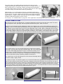
Maxx Products (MPI) #MX-9104 Micro ESC (Electronic Speed Controller) 1 gram
7-cell 350mAh Ni-Cd (nicad) Battery Pack 95 grams
7-cell 500 mAh NiMH (nickel metal hydride) Battery Pack 96 grams
These are the components that are shown in this manual and on the plans. We did not
use an On/Off switch in this airplane because of weight considerations. The battery is
simply plugged and unplugged from the ESC before and after each flight. Different
brands of receivers, servos, and ESC’s may be usable with this design, provided they
are of similar, or lighter, weight and size. For obvious reasons, standard radio
components cannot be used with the Demoiselle
A 7
-
cell battery pack is used in the Demoiselle for two very good reasons. The first has
to do with the C.G. realities. With virtually no nose moment, the Demoiselle needs a
substantial battery pack to get the airplane to balance and the 7-cell pack does just
that. The second reason is flight duration. With throttle management, the 7-cell
350mAh Ni-Cad battery pack keeps our Demoiselles flying for anywhere from 8 to 12
minutes. We’ve also used 7-cell 500 mAh NiMH (Nickel Metal Hydride) battery packs
with good results. In general, the difference between this type of cell and the 350 mAh
NiCad cell is that the NiMH pack seems to deliver a little less power with some
incremental increase in duration. Both types of cells weigh the same, so they are both
usable. Last, the battery pack should be configured in the "hump" shape -
four cells on
the bottom, three cells on top. This layout offers the most mass in the least amount of
space and this is very helpful when making small changes in the C.G. location, if
needed.
For maximum flight performance, indoor R/C models require attention to the weight of everything they must carry aloft, including
connectors. We used and like the small 2-prong Dean’
s connectors for connecting the battery pack to the ESC. Recently, Cloud
9 Micro R/C announced the availability of their new micro connectors. We’ve seen and used these and can recommend them
for use with the Demoiselle. There are many other connectors available on the market. Be sure to choose your connectors with
weight, size, and efficiency considerations in mind.
Last, our radio systems include excellent transmitters, providing us with features such as servo throw adjustments (EPA), servo
reversing, servo sub-trim adjustments, etc. Our trusty Airtronics® RD-6000 Sport transmitters and the equivalent HiTec™ units
have taken care of all these needs.
Required Tools
For proper assembly, we suggest you have the following tools and materials available.
A selection of glues: SIG Thin CA, SIG Medium or Thick CA, SIG Thin CA Applicator Tips, SIG Kwik-Shot CA
Accelerator and a Heat
-
Activated Covering Adhesive, such as SIG Stix
-
It or Solarfilm Balsaloc.

.
A selection of hand tools, such as: Regular size and miniature screwdrivers, Regular size and miniature pliers (flat nose,
needle nose, round nose), Tweezers and/or small hemostats and a Hobby knife with sharp #11 blades
Sandpaper - assorted grits
Modeler’s "T" pins
Power drill and hand "pin vise" (for small diameter drill bits) Assorted drill bits, including: .031" (1/32" or # 68),
.046" (3/64" or # 56), .063" (1/16" or # 52), .078" (5/64" or # 47), .093" (3/32" or # 42) and .109" (7/64" or # 35)
Paint
We used very little paint on our Demoiselle models. Only the most conspicuous details -
dummy engine, wheels, seat back, and
the optional gas tank - were painted on our models. This turns out to be just about right in making the model look the way it
should. Avoid using too much paint. Keep the overall look simple, like the real airplane. We used two basic paint types for our
Demoiselle models
-
Testors Model Master™ plastic model paint and waterbased acrylic craft paints.
The dummy engine and optional dummy gas tank were painted with Testors Model Master™ paints, using the spray can
products whenever possible. The engine was sprayed Flat Black. The exhaust pipes were painted with Exhaust Buffing
Metalizer and the lifters and pushrods were painted with Brass Buffing Metalizer. The sparkplug bodies were painted with Flat
White or White Primer and the dummy gas tank was painted with Navy Aggressor Gray, to simulate metal.
The wheels, seat back, and rudder pedals were painted with water-
based acrylic craft paints. These very inexpensive paints are
sold in the craft departments of stores such as Wal-Mart, K-Mart, and similar outlets. They seem to be manufactured under
many different brand names, such as Delta Ceramcoat™ and Apple Barrel Colors™. They are available in a huge variety of
colors. We found that thinning these paints with equal amounts of water produced nice results, when either brushed or sprayed,
with no appreciable weight build
-up. Clean-up is also easy, using just warm water. We painted the seat back with a light brown
color to create a nice contrast to the balsawood. The wheels can be painted with a light gray, simulating a metal effect or a light
brown color to create the look of wood. We used a darker gray to paint the rudder pedals. Remember to paint these details
before installing them into the airframe.
COMPLETE KIT PARTS LIST
Balsa Sticks
1 1/16"x1/4"x24" W1 Rib Stiffeners 12 1/8"x1/8"x36" Fuselage, Elevator,
Rudder, LGS Struts, Wing Tip Braces
1 3/16"x3/16"x36" Fuselage Top
Longeron, Universal Joint
Supports
1 3/16"x3/8"x3/4" Servo
Mount Supports
1 1/4"x1/4"x2" L.G. Strut Anchor
Blocks
4
1/4" dia. x 36" Balsa Dowels; for Wing
L.E., Wing T.E., Wing Cuff L.E., L.G.
Spreader Bar
Laser-Cut Balsa
1 1/32" thick Sheet #1: WSP, Seat
Back
1
1/16" thick Sheet #2: FP1, FP2, FP11,
WHL, RXP, Rudder Pedals
1 1/8" thick Sheet #3: FP3, FP4,
FP5, FP7, FP12, FP15, W1
1
1/8" thick Sheet #4: W2,
WG, WHB, R1, E1
1 1/4" thick Sheet #5: DBR, Exhaust
Pipes
Laser-Cut Plywood
1 1/64" plywood Sheet #6: FP6, FP8,
FP9, FP10, FP13, FP14, FD1, FD2,
FD3, FD4, LGS4, CHN, UNV
1 1/32" plywood Sheet #7: WSF, WHC,
WRT, DEM
Hardwood
1 5/16" basswood Motor Mount, laser-
cut
3 10" Bamboo Sticks; for Front Rigging
Mast , Rear Rigging Mast, Tail Skid,
Control Stick, Bottom Rigging Posts
1 1/8"x3/16"x1-1/2" Spruce
Stick; for Servo Mounts
Wire Parts
1 .020" dia. x 18" Straight Wire; for
Rigging Hooks
2 .046" dia. x 2-1/2" Straight Wire; for
Axles
Hardware
1 #1 x 3/8" Sheet Metal Screw; for
motor attachment
2 .090 x 1/8" Round Brass Machine
Screw; for Pilot
2 .090 Brass Hex Nut; for Pilot 4 .090 Brass Washers; for
Pilot
Miscellaneous Parts
1 Molded ABS Plastic Dummy Engine 1 3/32" od x 1-5/8" Plastic Tube; for
Universal Joint
32 1/16" od x 1/4" Aluminum
Tubes; for Wing Rigging Points
& Swage Tubes
2
1/8" od x 1/2" Aluminum
Tubes; for Universal
Joint
4 1/4" id x 1" Aluminum Wing Mount
Tubes
1 10 ft. Monofilament Pull-Pull Line 1 8 yds. Elastic Thread; for
rigging wires
1 2 ft. Dacron Thread
1 36" Rubber Tubing; for Tires 1 19-1/2"x72" Covering Material, color:
white
1 3/4"x3" long Velcro® 1 Pilot Sheet
1 Decal Sheet 1 Full-Size Plan 1 Assembly Manual

.

.
Laser
-
Cut Parts
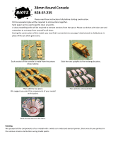
When it is time to remove the part from the sheet, use a sharp #11 hobby knife to slice through the small bridges that hold the
part in the sheet. Do not try to push the parts out of the sheet without first cutting through the bridges, or you may end up with a
lot of broken parts.
FUSELAGE CONSTRUCTION
1.
Start by constructing the four simple formers that are shown in CROSS-SECTIONS A, B, C, and D of the full-size plan.
Build these parts directly over the plan drawings to insure perfect accuracy. Build only the shaded portions of the cross-
section drawings, the other parts will be added later.
NOTE: Don't forget to put wax paper or plastic wrap over the plan to keep the parts from sticking.
Cross-Section A former consists of two pieces of 1/8" sq. balsa stick,
plus parts FP4 and FP7.
Cross-Section B former consists of two pieces of 1/8" sq. balsa stick,
plus parts FP5 and FP6.
Cross-Section C former consists of two pieces of 1/8" sq. balsa stick,
plus part FP6.
Cross-Section D former consists of three pieces of 1/8" sq. balsa stick,
plus part FP6.
Once these formers are dry, they can be removed from the plan.
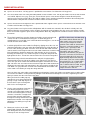
2.
Cover the Fuselage Bottom Frame drawing with wax paper or plastic wrap for protection. Using 1/8" square balsa sticks
plus laser-
cut parts FP1, FP2, FP3, FP10, and FP15, construct the fuselage bottom frame directly over the drawing. Leave
the bottom frame assembly pinned to the plan for now, even after the glue is dry.
NOTE:
Be sure to cut the longest pieces of 1/8"
sq. balsa first, then the shorter pieces,
in order to make the most efficient use
of the stock 36" long sticks. This is good
advice for this step and throughout the
entire construction of this airplane.
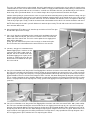
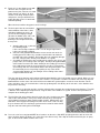
3.
Next locate the 3/16"x3/16"x36" balsa stick for the Fuselage Top Longeron. Lay it
in place on the full-size plan and trim both ends to proper angle and length (save
the leftover ends). Also, while you have the Top Longeron in position on the plan,
carefully mark on the bottom of the Longeron the exact locations for the four
formers and any other parts that will be attached to the Longeron. Be precise!
These marks will be critical for accurate assembly of the remaining parts.
4.
Using leftover stock from the previous step, cut to length and proper angle the
3/16" sq. balsa Rudder Post. Glue the rudder post in position on the bottom of
the fuselage top longeron, exactly 1/4" from the rear end of the longeron. Then
glue 1/64" plywood part FP9 on the front of the rudder post.
5.
Pin, do not glue, the former A in position at the front of the fuselage bottom
frame. Also pin the two FP12 laser-cut parts in the corners to hold former A at
approximately the correct angle.
6.
Pin the front of the 3/16" sq. fuselage top longeron in position on top of former A.

.
7.
At the rear of the fuselage, pin the rudder post in position on the bottom frame.
Note that the rudder post should be glued on 1/4" from the end of the bottom
frame (as it was on the top longeron in step 4). The angle of former A should
automatically put the rudder post in approximately that location, provided you’ve
cut all your sticks accurately. If you find that you need to push or pull the rudder
post slightly fore or aft to get it in that location, notice that this will also change the
angle of former A slightly. As long as it’s not a significant amount, it should be
OK.
When you get everything pinned in correct position, you can glue the rudder post
and former A to the bottom frame.
8.
Glue the FP11 parts at the top of former A, one on each side.
9.
Now you can go ahead and glue the other three formers B, C, and D in position in
the fuselage. If you’ve done a good accurate job of construction so far, these
formers should fit perfectly in their locations. Be sure to glue all three of them in
with their FP6 plywood part facing the rear of the airplane.
10.
Next, glue the FP8 plywood gussets in the bottom corners of the formers B, C,
and D. Use A tweezers to hold them in position while you apply the glue.
11.
Glue a FP10 plywood part in position on
the upper crosspiece of former D.
12.
Cut to length and glue in position the
1/8" sq. balsa Diagonal Brace that runs
from the notch in FP12 up to the top of
former B. Make and install one for each
side of the fuselage.
13.
Cut to length and glue in position a 1/8" sq. balsa Vertical Brace to support the diagonal brace installed in the last step. The
top of this vertical brace should be 4-9/16" from the front of former A. The bottom should be 5-1/6" up from FP12. Make
and install one of these vertical braces for each side of the fuselage.
14.
Put a mark on both the diagonal brace
and the vertical brace exactly 1-1/2"
down from the top edge of the main
longeron. Do this on both sides of the
fuselage. Cut two 4-1/2" long pieces of
1/8" sq. balsa and glue them onto the
outside of the braces at the marks.
Then glue the balsa RXP radio platform
in place on top of the 4-1/2" long
pieces.
You can now unpin the entire fuselage
assembly from the building board.
15.
To make the Tail Skid, take one of the
10" pieces of bamboo provided and put
a pencil mark at 4-3/4" and 5-3/4" from
one end. The 1" area between these
two marks needs to be bent to form the
curved bottom of the tail skid, as shown
on the plan.

.
There are a lot of different ways to bend wood, but for this application we’ve found that the easiest method is simply to do a
"controlled break" of the area we want formed. In other words, we simply bend the bamboo slowly until it just starts to break.
Start with the tip of your thumb near one end of the 1" marked area. Bend the stick over your thumb until you feel it start to
break. Stop, move your thumb about 1/4" or so further along in the area you want formed, and then bend again.
Continue moving along in small increments in the area you want formed, bending it to the point of almost breaking, until you
have the shape you want. Don’t worry if a few strands of bamboo start to get loose on the outside of the curve. Once you’
ve
got the shape you want, thoroughly soak the entire bent area of the bamboo stick with thin CA to re-
strengthen it. When dry,
sand off any rough spots. Finally, cut off the unwanted end of the bamboo stick at the 5-3/4" mark and sand the end round.
NOTE: Don’t worry if the bend in your tail skid doesn’t match the plan exactly. The tail skids on the full-scale Demoiselles
were all a little different too.
16.
Glue plywood part FP14 about 3-1/4" from the top end of the tail skid. Then glue
the tail skid in place in the fuselage.
17.
Cut a 4-1/2" long piece of bamboo for the Control Stick. Sand both ends round.
Drill a .046" (3/64" or # 56) dia. hole near one end of the stick. This will be the
bottom end of the control stick. The hole is for the optional scale rigging wires
which will be added later.
Finally, glue the control stick in place in the fuselage as shown on the plan.
Be sure that the hole in the bottom of the control stick faces fore and aft.
18.
Cut two 1" long pieces of bamboo for the
Bottom Rigging Posts. Sand one end of
each post round. Drill a .046" (3/64" or
#56) dia. hole in the rounded end. Glue
the bottom rigging posts in place in the
fuselage as shown on the plan. Be sure
that the hole in the bottom of each post
faces fore and aft.
19.
Cut a piece of bamboo 2-3/4" long for the Front Rigging Mast. Sand one end of the mast round. Drill a .031" (1/32" or #68)
dia. hole in the rounded end. Next mark the correct location for the front rigging mast on top of the 3/16" sq. balsa fuselage
top longeron (see fuselage side view plan). Then glue plywood doubler FD1 on top of the longeron on that mark. Also glue
plywood doublers FD2 on each side of the longeron. Drill a 7/64" dia. hole down through the top longeron using the hole in
FD1 as a guide. Note that the hole should be drilled at an angle which will put the front rigging mast parallel to the fuselage
formers, not perpendicular to the top longeron. Finally, glue the front rigging mast in place, with the hole in its top running
span wise.
20.
Cut a piece of bamboo 2-1/8" long for the Rear Rigging Mast. Sand one end of the mast round. Drill a .046" (3/64" or # 56)
dia. hole in the rounded end. Mark the correct location for the rear rigging mast on the top of 3/16" sq. balsa fuselage top
longeron. Glue plywood doubler FD3 to the longeron on that mark. Glue plywood doublers FD4 in position on each side of
the top longeron. Drill a 7/64" dia. hole down through the top longeron using the hole in FD3 as a guide. Drill the hole at an
angle so that the rear rigging mast should be parallel to the fuselage formers, not perpendicular to the top longeron. Glue
the rear rigging mast in place, with the hole in its top facing fore and aft.

.
21. The two 1/4" thick laser-cut balsa DBR dihedral braces are identical in size and
shape. Glue one DBR in position on the back of former A and the other one on the
back of former B. Study the side view plan and the cross-section drawings
carefully to be sure that you understand exactly where the dihedral braces should
be located. In both cases, the DBR dihedral brace must be installed with its
bottom edges perfectly flush with the bottom edges of the FP4 and FP5 pieces
that are already built into the respective formers.
22
With a cloth rag, rub as much of the dark soot off the lasercut edges of the
Hardwood Motor Mount as possible. Then glue the motor mount in place on the
fuselage.
23.
Laser-cut part FP15 is the back of the pilot's seat. Before it can be glued in place in the fuselage, it needs to be formed into
the curved shape you see in the pictures. Try to locate a cylindrical object of about 2" diameter to serve as a form for the
seat back (a 4 oz. jar of Sig Supercoat Dope is perfect). Soak FP15 thoroughly with water and secure it to the 2" diameter
form with rubber bands or tape. Let dry overnight. When you take it off the form the next day, it will stay curved and can be
easily glued in position in the fuselage.
Set the fuselage aside until needed later.
WING CONSTRUCTION
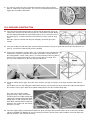
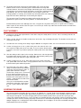
24.
Four 1/4" dia. balsa dowels are provided for making the leading and trailing edges
of the wings. Notice that each dowel has a 6-1/8" long slot in one end. Glue a
1/32" plywood WSF wing stiffener in each slot with thin CA. Make sure the edges
of the WSF plywood do not protrude outside the diameter of the dowel. When dry,
sand very lightly to smooth out any rough spots. Then trial fit the stiffened end of
the dowel inside one of the 1/4" id aluminum wing mount tubes. If the dowel is too
big, gradually sand it down until it fits properly. You want the wing dowel to fit
inside the aluminum tube with a little bit of friction, but not too much.
The idea is to achieve a snug fit that will hold the dowel in place, yet allow the
dowel to be easily removed when you want to take the wings off your airplane.
Obviously, you don't want it so loose that
the dowel falls out.
25.
Lay each of the four dowels in place on
the wing plan, one for each Trailing
Edge and one for each Main Leading
Edge. Make sure the plywood-
reinforced
end of the dowels is at the root end of
the wing panels. Then mark and cut the
dowels to proper length (don’t throw
away the leftover balsa dowel, it will be
needed for other parts).

.
26.
Cover your wing plans with wax paper or plastic wrap for protection. Working on one wing panel at a time, pin the trailing
edge, main leading edge, and ribs in exact position on the plan.
Double check to see that you have the plywood reinforcements in the root ends of the dowels situated vertically for
maximum strength. After these parts are securely pinned in place, glue all the joints with thin CA.
NOTE: It’s best not to push pins through the leading and trailing edges. Instead, straddle these narrow parts with crossed
pins pushed into the building board. Look closely at the photos and you
’
ll see what we mean.
27.
Glue a 1/16"x1/4" balsa cap strip along the inside of the root wing rib. It should be flush with the top edge of the rib.
28.
Glue in the WG balsa wing gussets in the four corners of the wing panel.
29.
Cut to length and glue in position the 1/8" sq. balsa Tip Braces. (See photo above)
30.
Use a 90 deg. triangle to mark the locations of the four 1/16" od x1/4" Aluminum Tube Rigging Points onto the outer faces
of the appropriate wing ribs. Glue the rigging points to the ribs at those locations. Be careful not to get any glue inside the
tubes.
31.
Unpin the leading edge and wing ribs from the plan. Leave the trailing edge pinned down! Carefully lift the entire leading
edge of the wing panel up 3/8" above the building board. Place 3/8" thick pieces of scrap balsa, hardwood, or whatever
you can find, underneath the leading edge to hold it up off the board. Pin the leading edge securely to the 3/8" spacers.
32.
Cut a 1/4" dia. balsa dowel to 10-5/8" long for the Cuff Leading Edge (from the
leftover of Step 2). Pin the Cuff Leading Edge and four W2 ribs in place on the
front of the wing panel. With the Cuff Leading Edge pinned down against the
building board, and the Main Leading Edge up on the 3/8" spacer blocks, the W2
ribs should flow smoothly into the contour of the W1 wing ribs.
When everything is satisfactorily positioned, glue all the joints with thin CA.
33.
Glue in the two WG wing gussets that go in the cuff area of the wing panel.
34.
A piece of 1/4" sq. x2" balsa stick is provided for making the L.G. Strut Anchors. Cut the pieces 1/4" long, which will mean
you end up with a 1/4"x1/4"x1/4" balsa cube. Glue these pieces into the wing structure where shown on the plan. Pay
attention to the grain direction when gluing them in (see plan).
35.
When dry, the entire wing panel can be removed from the building board. Double-
check all the joints for adequate glue and
apply a little more if necessary. Clean up any rough edges with a fine grit sanding block.
Repeat Steps 26 through 35 to construct the opposite wing panel.
36.
Sand the outside of the four 1/4" id x1" Aluminum Wing Mount Tubes with 220
grit sandpaper to improve glue adhesion. Then slip the wing mount tubes onto
the root ends of the leading and trailing edges of both wing panels.
Now trial fit one of the wing panels to the fuselage, resting the wing mount tubes
in position against the DBR dihedral braces in the fuselage.
When you have the wing panel lined up properly, have a helper put a single drop
of thin CA glue between the aluminum tube and DBR. Don’t over glue at this
point or the excess glue might seep inside the tube, permanently gluing your wing
panel into the tubes.
After tack gluing both the front and rear tubes to the dihedral braces, have your
helper slowly pull the wing out of the tubes, while you continue to hold pressure
against the tubes, keeping them from breaking loose.
After the wing is removed, re
-glue the wing mount tubes securely to the
surrounding fuselage structure with medium or slow CA. Avoid getting any glue
inside the aluminum tubes.

.
After one set of wing mount tubes has been installed, repeat the same procedure to install the wing mount tubes for the
opposite wing panel.
Set the wings aside until needed later.
LANDING GEAR CONSTRUCTION
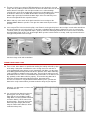
37.
Carefully remove the following parts for the wheels from the laser-cut sheets:
48 - WSP wheel spokes from sheet #1
4 - WHL wheels from sheet #2
4 - WHB wheel hubs from sheet #4
4 - WHC wheel hub caps from sheet #7
38. Use a #11 hobby knife to cut loose the "pie shaped" scrap pieces between each
of the spokes of the WHL parts.
39.
Notice that two of the WHL pieces will be laminated together to form the basic
core of one wheel assembly.
However, before gluing them together, use a flat sanding block with medium grit
sandpaper (100 to 200 grit), to bevel the outer edge of each WHL piece. Hold the
sanding block at a 45 deg. angle. Bevel only one side of the piece.
The purpose of the beveled edge is to provide a groove for the rubber tire to fit in
after the WHL pieces are laminated together with their beveled edges facing each
other.
40.
It’s very important to work on a perfectly flat surface when gluing the WHL pieces together to insure that the laminated
wheel comes out flat.
First lay a piece of waxed paper down on the flat surface.
Next lay a WHL piece down on the waxed paper, with the beveled side up.
Note which way the grain runs through that WHL piece. Position the second WHL piece on top of the first one. Make sure
this one is beveled side down. Also make sure the grain direction of the top WHL is 90 deg. to the grain direction of the
bottom piece. This will provide maximum strength to the finished wheel.
Carefully match up the spokes of the
two WHL pieces exactly. When satisfied
with the positioning, hold the parts
tightly together with a flat block and
place a drop of thin CA glue at the outer
edges. Continue placing small drops of
thin CA around the entire perimeter of
the WHL pieces, until they are solidly
glued together.
It will dry very quickly. Then you can pick up the laminated part and continue gluing along the spokes and hub areas.
NOTE: It's best to use a fine applicator tip on your CA bottle during assembly of these wheels. Actually a fine tip is best for
the assembly of the entire kit.
Building feather-light models like the Demoiselle requires that we change our thinking a bit from the old habits we've used
in building much heavier sport type models. With the small parts involved here, it's not desirable to flood a large area with a
lot of glue. It's much better to get a little glue exactly where you need it, and a fine applicator tip does that for you.

.
41. Next, glue a 1/8" balsa WHB wheel hub and a 1/32" plywood WHC wheel hub cap onto each side of the wheel assembly.
To insure that the center holes in all these parts are in correct alignment, it’s best to first dry assemble all these parts onto
a piece of .046" dia. x2-1/2" music wire (provided for the axles) as shown. Then, while holding everything snuggly together
put a small drop of thin CA glue into each joint. Don’t get any glue on the wire!
When dry, you can take the wire out and put a little more glue on the joints if they need it.
42.
Glue the 1/32" balsa WSP wheel
spokes in place on each side of the
wheel.
Again, use thin CA and a fine applicator
tip to keep the glue application to a
minimum.
43.
If you want to paint your wheels, do it
now.
COLOR MY WHEELS:
For esthetic purposes, you may want to paint your wheels before the tires are put on. We painted ours either
gray to simulate steel wheels or brown for wood wheels. It's your choice and a matter of personal
preference. Thinned out acrylic latex "craft paint" works very well, or thinned butyrate dope. Whatever you
use, one coat is all that is necessary. A completely filled glossy paint job is not necessary or desirable, and
it's too heavy for this type of model. One coat achieves the "old time" look we are after.
COLOR MY TIRES:
The amber colored surgical tubing that is provided for the tires can be easily dyed black with regular
household variety Rit Dye.
44.
Complete the wheels by gluing a piece of surgical tubing around the outside to serve as the tire.
Again, use thin CA and a fine applicator to keep the glue application under control.
Start by tack gluing one end of the tubing in place in the groove with a single drop of glue. Now work your way slowly
around the perimeter of the wheel, lightly gluing the tubing in the groove as you go. It’s not necessary to stretch the tubing
as you put it on, simply make sure you are keeping it straight and not weaving side to side. When you get to the last 1" or
so, stop gluing.
Carefully measure and cut off the unglued end of the tubing to proper length to
mate up with the first end. Prepare a small "splice" to go inside the two ends of
the tubing. A balsa stick approximately 1/16" square x1/4" long should be about
right. Cut it from a piece of scrap 1/16" laser-cut balsa sheet. Glue it halfway
inside one end to the tubing, and then join the other end up to it. Holding
everything in position, finish gluing the end of the tire to the wooden wheel.
Set the finished wheels aside for now.
45.
Cut a piece of 1/4" dia. balsa dowel to 7-3/4" long for the main landing gear
Spreader Bar. Tightly wrap each end of the spreader bar with dacron thread as
shown on the Fuselage Front View plan. Soak the thread wrapped area
generously with thin CA glue and then wipe dry with a rag.
45.
Drill a .046" dia. hole in each end of the Spreader Bar. Make the holes about
15/16" deep. Then glue a .046" dia. x2-1/2" straight music wire Axle in each hole.
Leave 1-9/16" of the Axle sticking out of the Spreader Bar.
46.
Glue the Spreader Bar in place on the bottom of the fuselage.

.
47. Bend six L.G. Strut Hooks out of .020"
dia.music wire, using the full-size
pattern on the plan. Glue the L.G. Strut
Hooks into the 1/4" balsa L.G. Strut
Anchors in the wing. Study the plans
and pictures closely to determine the
proper direction each L.G. Strut Hook
should be pointing.
When finished, install the wing panels on the fuselage.
48.
The basic procedure for construction
and installation of the LGS1, LGS2,
and LGS3 landing gear struts is to
(a) first cut them roughly to length,
(b) make the bottom (axle) ends, and
(c) fit the struts on the airplane for
trimming to final length and finishing
the top ends.
a. Start by cutting 1/8" sq. balsa to
the following lengths:
LGS1 = 9-5/8" long 2 required, LGS2 = 12-1/4" long 2 required and
LGS3 = 9-3/4" long 2 required
b. Glue two 1/64" plywood LGS4 doublers on one end of each of the six
landing gear struts. When dry, sand the end of the balsa to match the
rounded shape of the doublers. Drill a .046" dia. hole completely through
the stick, using the holes already in the doublers as a guide.
c.
Assemble the landing gear struts and the wheels onto the wire axles in the
proper order (see Fuselage Front View plan). Do not put the plywood WRT
wheel retainer on at this time. Now, working on one landing gear strut at a
time, hold the top end of the strut up against its specific L.G. Strut Hook
and carefully mark the exact location that the wire will go through the strut.
Be careful that you are not pushing or pulling on any of the model
structure while doing this or you could get a false reading of the actual
length needed for that strut.
Take the strut off the airplane and install two LGS4 plywood doublers at the hole location you just marked. Make sure you
are putting the doublers on the correct sides of the strut! It's easy to make a mistake! The LGS2 struts have their top and
bottom doublers on the same sides of the stick because both wires go through the strut in the same direction. For the
LGS1 and LGS3 struts, the strut hook wires at the top go through the stick 90 deg. to the axle wire, so the doublers must
be put on the same way.
Once the doublers are glued on and dry, sand the end of the balsa to match the rounded shape of the doublers. Then drill
a .046" dia. hole completely through the strut, using the holes in the doublers as a guide. Use the same procedures to
complete all the landing gear struts.
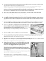
49.
Trial fit all the LGS struts and the wheels back on the axles. Hook the tops of the
struts to the strut hook wires. If they were made correctly, they should go on
easily without inducing any warps into the model structure. Note that the strut
hook wires at the top are loose fitting in the holes of the struts. That’s the way
they are meant to be! The small angle you bent on the end of the hook should
keep the strut from coming off in normal flight.
50.
Press the 1/32" laser-cut plywood WRT wheel retainers on the axles. Slide WRT up tight against the stack of struts and
wheel, and then back it off about 1/32" so the wheel can still turn freely. Put a drop of medium or thick CA glue, or epoxy
glue, on the outside of WRT to hold it on the axle.

.
51. Use 2 pair of needle nose pliers to bend the remaining outer end of each axle
down as shown on the front view plan. This serves as an attachment point for the
rigging wires that will be added later.
TAIL SURFACES CONSTRUCTION
52.
Cover the Elevator plan with wax paper or plastic wrap for protection. Using 1/8"
square balsa sticks plus the two laser-cut parts E1, construct the elevator directly
over the drawing. Remember to cut the longest pieces of 1/8" sq. balsa first, then
the shorter pieces, in order to make the most efficient use of the stock 36" long
sticks.
When dry, unpin the elevator from the plan and lightly sand all the glue joints
smooth.
53.
Cover the Rudder plan with wax paper or plastic wrap for protection. Using 1/8" square balsa sticks plus the two laser-cut
parts R1, construct the rudder directly over the drawing.
54.
Using a new sharp blade, carefully slit the 1/8" sq. balsa where the CHN plywood
control horns need to be installed in the elevator and rudder (see plan). Because
the CHN plywood is so thin (1/64"), there is no need to actually remove any wood
from the slot. A single cut through the center line of the balsa is enough. Then
press the CHN control horns in the slots and glue with thin CA.
55.
Trial fit the rudder into the gap in the center of the elevator. If the gap is too tight, sand it larger until the rudder slides in
easily.
NOTE: When you first start sliding the rudder into the elevator, you will need to keep the front of the rudder up tight against
the elevator's center spar in order for the rudder trailing edge to clear the elevator trailing edge.
Then, after you’ve got the rudder
properly lined up, simply slide it back
until the notch in the rudder trailing edge
captures the elevator trailing edge. Both
trailing edges should end up flush at the
back. When satisfied that the rudder fits
properly in the elevator slot, take it back
out for the next step
56.
Cover the rudder and the elevator with the white Lite-Span covering material provided. Refer to the section of this booklet
called "COVERING THE WINGS" for general covering instructions. Note that the rudder should be covered on both sides,
while the elevator is only covered on the top.

.
57.
After the rudder is covered on both sides, put on the decals. It
’s a lot easier to put them on now, while the rudder can be
laid flat on your workbench, than later when the rudder is mounted on the fuselage.
The decals provided in the kit are self-stick mylar stickers. They should not be dipped in water! Simply cut out the decal
design with a sharp hobby knife or scissors, cutting as close to the image as possible. Remove the design off the backing
paper with a tweezers and carefully place it position on the model part. Gently rub the decal onto the part with the tip of
your finger.
58.
Now slide the rudder back into the gap in the center of the elevator (like you did in Step 55). Line it up carefully in final
position, and then glue it in place with thin CA. Set the tail surfaces aside for now.
59.
Next we’ll assemble the Tail Group Universal Joint (see detail drawing of the universal joint on the plan). From the
hardware bag locate the two 1/8"x1/2" aluminum tubes and the single piece of 3/32"x1-5/8" white plastic tubing. From the
lasercut 1/64" plywood parts sheet, locate and remove the UNV part. For the following steps you will also need thin and
medium (or thick) cA glue with a small applicator tip. To "weld" the tubes together you will need a fine powder, such as SIG
Micro Balloons or baking soda.
Start by using a sharp single-edge razor blade to cut the 3/32"x1-5/8" white plastic tubing into a single 1" long piece and a
single 5/8" long piece, as called for in the drawing. Set these aside for assembly.
60.
The two pieces of 1/8" od x1/2" aluminum tubing will now be glued together,
forming the cruciform pivot, which is the heart of the universal joint.
a. Lightly sand surfaces of both tubes with medium sandpaper to improve
glue adhesion.
b. Using a fine marker pen and a straightedge, accurately draw two lines on
your workbench (or on a piece of paper laying flat on your workbench) at
90 deg. to each other. This will be the template for joining the two
aluminum tubes. Cover the intersecting lines with a small piece of waxed
paper. Slip a length of 1/16th sq. balsa through one of the tubes. Tape the
1/16" sq. balsa piece directly over one of the lines and center the tube at
the intersection. Slip another length of 1/16" sq. balsa through the second
piece of tubing and tape the balsa stick accurately along the intersecting
line on the paper. Lift and visually center the tubing over the bottom piece.
When you are satisfied that you have the tubes in perfect alignment, use
thin CA glue with a small dia. applicator tip to place a SMALL drop of glue
on each side of the top tube, where it contacts the bottom tube.
c. Apply a SMALL amount of micro balloon powder (or baking soda) to each
side of the tube joint and set it with another single drop of CA glue.
Remove the tube assembly from the paper template and remove the 1/16"
sq. balsa sticks from the tubes. Turn the tube assembly over and apply a
SMALL amount of powder to the opposite tubing joints and again set the
joints with a single drop of thin CA glue. Inspect the assembly and add
more powder if needed. Set the assembly aside for now to dry thoroughly.
61.
Look closely at laser-cut plywood part
UNV and notice the four small nicks in
the two long sides. These nicks are
exactly 1/4" from the ends of the part.
Using a sharp hobby knife, lightly score
the surface of UNV between the two
nicks near one end..
Do the same between the two nicks on the other end. Now bend the ends of the part 90 deg., away from the score lines.
Put a tiny bead of thin CA glue in the bends to secure them in the 90 deg. position.
NOTE: Do not cut the score marks too deep or the ends will break off UNV when you bend them. Just drag the knifepoint
along the top surface, making a slight cut in only the first layer of veneer.

.
62. Carefully assemble the 5/8" long plastic tube (from step 59) and the aluminum
tube cruciform (from step 60) in the plywood UNV part, as shown. Place a tiny
drop of medium or thick CA glue (do not use thin CA for this task) on the outside
ends of the plastic tube to adhere it in the plywood. Set the glue with accelerator.
CAUTION: Do not use too much glue! If excess glue soaks past the plywood, it
could get inside the aluminum tube, gluing it permanently to the plastic tube.
63.
Cut two 3/16" sq. x1/4" long balsa
support blocks. Gently clamp the blocks
vertical in a small vise and drill
a .093" (3/32" or #42) dia. hole
completely through the center.
Assemble these support blocks and the
1" long piece of plastic tube (from step
59) to the universal joint.
Place a tiny drop of medium or thick CA glue on the outer ends of the balsa
support blocks, securing them to the plastic tube. Set the glue with accelerator.
64.
Fit the completed universal joint in place at the rear of the fuselage. You will need
to trim the 1/8" sq. balsa fuselage bottom longerons slightly to accept the
universal joint. When it fits properly, carefully glue the universal joint to the
fuselage structure with a few tiny drops of CA glue. Once again, be extremely
careful not to use too much glue, which could seep inside the aluminum tubes,
ruining the joint.
65.
Trial fit the rudder/elevator assembly onto the universal joint support blocks. Be sure to check the alignment of the tail
surfaces to the fuselage from the front view. When everything is satisfactory, carefully glue the tail surfaces permanently to
the support blocks with a few tiny drops of glue.

.
RADIO INSTALLATION
66.
A piece of 1/8"x3/16"x1
-1/2" long spruce is provided for servo mounts. Cut it into four 3/8" long pieces.
67.
The servo cutout at the rear of the RXP radio platform is for the rudder servo. Trial fit your rudder servo in the hole to make
sure it will fit. Adjust if necessary. Then glue 1/8"x3/16"x3/8" spruce servo mounts along the front and back lip of the
opening, on the top side of RXP. When dry, hold the rudder servo in position and mark the location of the mounting holes
onto the mounts. Drill pilot holes and then screw the rudder servo to the mounts.
68.
A piece of 3/16"x3/8"x3/4" long balsa stick is provided to make supports for the spruce servo mounts for the elevator servo.
Cut balsa stick into two 3/8" long pieces.
69.
Lay your elevator servo in place on the radio platform, with its control arm centered in the slot that is already cut in the
platform. Mark the correct locations for the elevator servo mounts on the platform. Glue the spruce servo mounts and the
balsa servo mount supports in place on the radio platform. When dry, drill pilot holes and then screw the elevator servo to
the mounts.
70.
The pull-pull control lines from the elevator and rudder servos back to the tail
surfaces are 6lb. test monofilament fishing line. A 10 foot long piece of
monofilament line is provided. Cut it in half into two 5 foot long pieces, one for the
elevator and one for the rudder.
NOTE: In all the hours of indoor flying
we've done with the Demoiselle and
other models, we've never found it
necessary to re-adjust the neutral
position of the rudder or elevator once
they were secured in position. If your
rudder servo is perfectly neutral
(including the trim lever on your
transmitter) and your rudder is
perfectly centered when you glue the
line to the servo arm, the trim lever on
your transmitter will easily cover any
flight trimming adjustments that may
be needed. If you ever need to replace
the pull-pull lines, it's a simple matter
to chip the glue off the nylon servo
arm, re-drill the hole if needed, and put
in new lines. Or simply replace the
output arm with a new one.
71.
Install the pull-pull lines to the rudder first. Begin by slipping one of the 1/16" od
aluminum swage tubes over one end of the monofilament line. Slide the tube up
the line a little, leaving you about 4-5 inches of line to work with. Now stick that
short end of the line through the hole in the left rudder control horn, and then loop
it back through the aluminum swage tube. Slide the tube up close to, but not
touching, the control horn. Use needle nose pliers to crimp the swage tube flat,
tight against the lines. Trim off the short end of the line close to the swage tube.
Now take the long end of the monofilament line and poke it up through the
outermost hole on the left side of the rudder servo control arm. Take the line
across the span of the control arm and down through the outermost hole on the
right side of the arm. Then take the line back to the right side rudder control horn.
Swage the line to the right side control horn in the same manner you did the left
side. Make sure you pull all the slack out of the monofilament line on both sides
of the rudder servo before you crimp the swage tube flat.
Once you have your entire radio system hooked up and functional, center your rudder servo output arm in neutral position.
Then center the rudder in neutral position by sliding the monofilament line through the servo arm, lengthening one side
while you shorten the other side at the same time.
When you have the rudder properly
neutralized, secure the pull-pull line by
placing a single small drop of glue on
the line where it passes through the
holes in the servo output arm.
72.
Use the same procedures from Step 71
to install the pull-pull lines for the
elevator servo. Note that the lower line
must be steered through the fuselage
structure. It should be a straight shot
from the lower elevator control horn,
through the fuselage framework, to the
bottom of the elevator servo output arm,
without the line rubbing on any of the
framework.
73.
Mount your receiver on the radio
platform with Velcro®. Run the antenna
back through the holes in the FP6 parts
at the top of each fuselage former.

.
74. The battery pack will be carried on the front platform (FP1) of the fuselage
bottom. Like the receiver, the battery pack is mounted to the fuselage with
Velcro®. However, due to the heavy weight of the battery pack, we’ve found that
Velcro®
alone is not enough to keep the battery securely in the airplane during all
flight attitudes. We also use a rubber band to l ash the battery pack to the
fuselage platform. In actuality, the Velcro®
keeps the battery pack from shifting in
flight, while the rubber band keeps it from leaving the airplane.
To prepare the front FP1 platform for rubber band mounting, glue the 1/64"
plywood FP13 parts to each side of the platform, as shown in the photo.
Bend two Battery Hooks from .020" dia.music wire, using the full-size pattern on the plan as a guide. Glue the battery
hooks in place on the outside of the FP13 parts. Use a No.32 (or similar size) rubber band stretched from one hook to the
other, over the battery pack.
PILOT ASSEMBLY
75.
Cut the pieces of the paper pilot from the sheet with a sharp #11 hobby knife or scissors. Cut as accurately and close to
the image as possible.
76.
Drill a 1/16" dia. hole in the shoulder and hip areas of the arms, legs, and body of the pilot. The locations for the holes are
marked by a black dot.
77.
Assemble the arms and legs to the body using the #00
-
90 x1/8" long brass bolts, hex nuts and washers that are provided.
78.
Cut two 1/2" long pieces of 1/8" sq. balsa. Glue one in the center of each 1/16"
laser-cut balsa rudder pedal, at the rear edge. These are mounts that the pilot’s
feet will be secured to. If you want to paint your rudder pedals, do it now and then
let dry.
79.
Glue the rudder pedals in place in the fuselage. Notice on the side view plan that
the rudder pedals must be glued in at a slight angle, approximately 30 deg. from
horizontal, so they will match the angle of the pilot
’
s feet.
80.
Cut two 1" long pieces of 1/8" sq. balsa. Glue them in the center of the pilot’s
seat, parallel with each other, with a 1/32" gap between them. These are mounts
that will hold the pilot
’
s bottom in position.
81.
Trial fit the pilot in the airplane. While
doing so, bend the pilot’s legs outward
at the hips to about a 45 deg. angle. A
gentle radiused bend is all that’s
needed, not a sharp crease. Then bend
the legs back inward at the knees so
that the feet fit onto the rudder pedals.
Bend the arms of the pilot in the same
manner - outward at the shoulder, back
inward at the elbow.
Once you’re satisfied with the location
and posture of the pilot, secure him to
the 1/8" sq. balsa mounts with a little
glue.
COVERING THE WINGS
The covering material included in this kit is Litespan, by Solarfilm. It is a strong, tough, heat-shrinkable synthetic covering
material. Litespan is very light weight, approximately 32 grams per sq. yard. Litespan is heat shrinkable, however it does
not have glue already on it. You must first apply adhesive to the model structure where you want the covering to stick,
using a heat activated liquid adhesive such as SIG Stix-It or Solarfilm Balsaloc (not supplied). Surface Preparation: Lightly
sand the parts to be covered, removing any bumps and unevenness that would show through the covering. Start with 80 or
100 grit sandpaper on a sanding block, and finish with 220 grit or finer sandpaper. Fill all cracks and hollows with light
weight model filler and sand smooth.

.
Coat the areas where you want the covering to stick with the heat-activated adhesive, following the manufacturer’s
instructions. On both wing panels, apply adhesive to the leading and trailing edges, the tip and root ribs and to the top
surface of each wing rib. Allow the adhesive to dry to the touch.
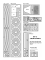
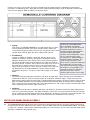
Cutting:
Refer to the "COVERING DIAGRAM" to see how to make best use of the
covering material provided. In the interest of light weight, only the top
surface of the wing panels will be covered. Also, only the top surface of the
elevator will be covered. Both sides of the rudder will be covered.
Pre-Shrinking:
Litespan is capable of shrinking a great deal. We have tried several
methods to control this tendency, including pre-shrinking the material.
Doing this tends to take some (not all) of the "shrink" out of the material.
This can be desirable when trying to minimize any tendency to warp the
part being covered. To do this, first cut the piece to shape (such as one of
the wing panels), leaving at least an inch or so of material around all
edges. Place the material on a clean, flat heat-resistant surface (dull side
up). With your iron set to about 200 deg.F, iron the material smooth,
shrinking it in the process. The piece is now ready to apply as described
below.
NOTES ON COVERING IRONS:
We’ve found that a small "trim
iron" (such as the Top Flite Trim Seal
Tool) works better than a full-size
covering iron when working with the
Litespan on light weight model
structures like the Demoiselle. In fact,
we use a trim iron for the entire
covering process, both adhering the
Litespan and then shrinking it. The
small size of the trim irons’ shoe
places heat in a small area, allowing a
lot of control. We can also tell you
from experience that using a heat gun
on Litespan is not a good idea. The
heat from a heat gun is difficult to
control and can cause uneven
shrinking, which in turn causes warps.
Adhering:
Set your covering iron temperature to between 195 deg.F and 210 deg.F. Lay the Litespan on the framework and
smooth out the wrinkles. Tack the Litespan in place at a few points around the edges, using the toe of the iron.
While tacking, gently pull the Litespan to get a smooth fit without large wrinkles. Do not try to get the Litespan drum
tight, just smooth and wrinkle free. Reheating and peeling back while hot allows the Litespan to be repositioned.
Then, seal the Litespan all around the edges of the wing with the iron. Trim surplus Litespan from around the edges
with a sharp blade and reseal the edges if necessary.
Shrinking:
Increase the iron temperature to between 250 deg.F and 285 deg.F. Shrink the Litespan by slowly sliding the iron
across the surface of the Litespan - just lightly touching the surface. Be very careful not to over-shrink the Litespan
because it will warp the light weight structure of the Demoiselle. Do not try to shrink out every last little wrinkle. Just
get rid of the largest ones. Remember; the full
-
scale Demoiselle also had wrinkles in the covering.
MOTOR AND DUMMY ENGINE ASSEMBLY
82.
The Hardwood Motor Mount on the front of the Demoiselle is designed to fit inside the 3/16"x5/16" opening in the back of
the plastic gear box of the GWS DX-
B electric motor. Trial fit the GWS motor onto the Hardwood Motor Mount. It should be
a snug fit. If it is too tight, sand the motor mount down slightly. If it seems too loose, you can shim around the motor mount
with paper, cardboard, or thin plywood scrap.

.
83.
A #1 x3/8" sheet metal screw is provided to hold the GWS electric motor to the
hardwood motor mount for flight. The screw will go in from the front of the motor
and be accessible through one of the round openings in the motor’s front gear.
Start by drilling a .078" (5/64" or #47) dia. clearance hole for the screw through the
front wall of the motor’s plastic gear box. Locate the hole so it will be within the
3/16"x5/16" opening in the back (thus hitting the hardwood motor mount) and so it
is accessible through one of the openings in the front gear - study photo
thoroughly. After you’ve got that hole drilled, slide the motor back on the
hardwood motor mount and drill a 1/32" dia. pilot hole into the hardwood mount for
the screw. Thread the screw in snugly so that the front gear will clear it when the
motor is turning.
84.
The scale-like dummy 2-cylinder engine provided with your kit adds a nice look to
the finished airplane. The engine is molded from .010 thick plastic, in two halves.
Making the engine is not difficult, provided attention is paid to these instructions.
Our finished, fully detailed and painted dummy engines typically weigh just 3
grams!
Use a sharp pair of scissors to trim the excess flat plastic to within about 1/16" of
the perimeter of both molded engine halves.
85.
Note that the engine is molded with a "front" and "rear" face. The front is flat, while the rear has a beveled shape. Use a
small scissors or a sharp hobby knife to remove the front face of both motor halves, leaving about 1/16" around the edges.
86.
From the kit contents, locate the laser-cut 1/32" plywood DEM part. Center the DEM part carefully into the inside front face
of one of the molded engine halves, with its half
-
round motor cut
-
out facing up. Use thin CA to glue it in place.
87.
Place the remaining engine half in place over the DEM former, aligning it carefully with its mate. Hold one of the cylinder
heads together, visually aligning the halves and use a drop of thin CA on the seam to hold it in position (in the case of thin
CA and plastic, less is always better). Move over to the opposing cylinder head, again aligning the two halves, and glue the
halves together at the head with a drop of glue. Work around the seam perimeter, using a drop of glue about every 1/2" or
so, until the halves are fully joined.
88.
The excess glued seam is now carefully sanded. Use 220 grit sandpaper and do not attempt to eliminate the seam, but
rather work to make it as uniform as possible. When the engine is painted flat black, the seam lines become very muted and
blend in nicely.
89.
In order to fit over the GWS motor and
the fuselage motor mount, the dummy
engine must have a 3/4" wide slot cut
out from the top of its rear, rounded face,
down and forward to the DEM ply mount.
This is quickly done by first marking the
approximate cutting lines onto the
engine with a fine-line marker and using
small scissors to remove the material.
Note that when this material is removed, the engine assembly gets a little easier to bend, so handle it carefully.
Page is loading ...
Page is loading ...
Page is loading ...
Page is loading ...
Page is loading ...
Page is loading ...
Page is loading ...
Page is loading ...
Page is loading ...
-
 1
1
-
 2
2
-
 3
3
-
 4
4
-
 5
5
-
 6
6
-
 7
7
-
 8
8
-
 9
9
-
 10
10
-
 11
11
-
 12
12
-
 13
13
-
 14
14
-
 15
15
-
 16
16
-
 17
17
-
 18
18
-
 19
19
-
 20
20
-
 21
21
-
 22
22
-
 23
23
-
 24
24
-
 25
25
-
 26
26
-
 27
27
-
 28
28
-
 29
29


Ask a question and I''ll find the answer in the document
Finding information in a document is now easier with AI
Related papers
Other documents
-
Ginger USA 0218CT-10-10/PC Installation guide
-
Rimage Everest 400 Owner's manual
-
 Game Of Bricks UCS 7181 Light Kit for Star Wars TIE Interceptor User manual
-
 Cleveland E-Zee Thunderstreak F-84F User manual
-
 BLOTZ B28-SF-235 Assembly Instructions
-
HERMA HIDE IT User manual
-
Alien AAC505 User manual
-
soundskins 239SSPROSK User manual
-
 HERR HRR505 User manual
-
Kyosho VZW224 User manual


