Brandt WFE0605K Owner's manual
- Category
- Washing machines
- Type
- Owner's manual
This manual is also suitable for

SERVICE MANUAL

2
TABLE OF CONTENTS
PAGE
1. Specifications 3
1.1. Product Specifications 3
1.2. Name Plate 3
2. Installation Instructions 4
2.1. Moving and Installing 4
2.2. Detergent Box Group 5
3. Operating Instructions 6
5.1. LCD Screen, Function Buttons & Knobs 6
5.2. Program List 6
5.3. Program Details 7
5.5. Child Lock 8
4. Test Mode 9
6.1. Autotest 9
5. Service Mode 11
5.1. Service Autotest 11
5.2. Failure Codes 12
6. Troubleshooting Guide 12
7. Disassembly and Assembly Instructions 14
7.1. Top Plate 14
7.2. Door 14
7.3. Tub Bellows Seal 16
7.4. Detergent Drawer 16
7.5. Control Panel 16
7.6. Kick Plate 18
7.7. Front Panel 18
7.8. Upper Support Bracket 20
7.9. Detergent Drawer Housing 20
7.10. Power Cable Group and Parazit Filter 21
7.11. Electronic Pressure Switch (EPS) 22
7.12. Door Lock 22
7.13. Pump Motor 22
7.14. Front Counterweight 23
7.15. Heater 23
7.16. Tub Bellows Seal 24
7.17. Transport Screw 24
7.18. Upper Counterweight 25
7.19. Washing Group 25
7.20. Shock Absorber PIN 26
7.21. Belt 26
7.22. Driven Pulley 26
7.23. Motor 26
7.24. Tub Entrance with Bellow Hose 27
7.25. Pressure Switch Hose Group 27
7.26. Tub 27
7.27. Drum 27
8. Component Specifications 28
8.1. Drain Pump 28
8.3. Resistance 30
8.4. NTC 32
8.5. Valve 34
8.6. Electronic Pressure Switch (EPS) 36
8.7. Motor 37
8.8. Door Lock 40
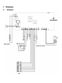
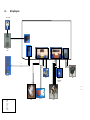
9. Wiring Diagram 42
9.1. Wiring Diagram NA-127VB3 and NA-147VB3 42

3
1. Specifications
1.1. Product Specifications
42 lt
Product Type
R Serisi
Capacity
5 kg
Max Spin Speed (r/min)
400 – 500 600 – 800 - 1000
Energy Consumption
A+
Control Panel
R1 – R2
Wash Programs
15 settings
Dimensions
Height
84,5 cm
Width
59,7 cm
Depth
49,7 cm
Other Features
Child Lock
Delay Time
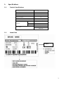
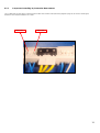
1.2. Name Plate
0000
SERVICE INDEX
NUMBER

2. Installation Instructions
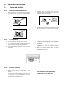
2.1. Moving and Installing
2.1.1. Removal of Transportation Screw
1. Transportation screws, which are located at the back
side of the machine, must be removed before running
the machine.
2. Loosen the screws by turning them anticlockwise with a
suitable spanner.
3. Pull out the screws and rubber washers.
2.1.2. Foot Adjustment
1. Do not install machine on rugs or similar surfaces.
2. For machine to work silently and without any vibration, it
should be installed on a flat, non-slippery firm surface.
Any suspended floor must be suitably strengthened.
3. You can adjust the level of machine using its feet.
4. First, loosen the plastic adjustment nut away from the
cabinet base.
2.1.3. Electrical Connection
1. Washing machine requires a 50Hz supply of 220-
240Volts.
2. A special earthed plug has been attached to the supply
cord of washing machine. This plug must be fitted to an
earthed socket. The fuse value fitted to this plug should
be 13 amps. If you have any doubts about electrical
supply, consult a qualified electrician.
4. The holes where the transport screws have been
removed should be covered with the plastic transport
caps found in the accessories bag.
5. The transportation screws that have been removed from
the machine must be re-used in any future transporting
of the machine.
5. Change the level by adjusting the feet upwards or
downwards.
6. After level has been reached, tighten the plastic
adjustment nut again by rotating it upwards
against the base of the cabinet.
7. Never put cartons, wooden blocks or similar
materials under the machine to balance
irregularities of the floor.
THIS APPLIANCE MUST BE EARTHED.
Insert the machine’s plug to a grounded
socket which you can easily reach.

5
2.1.4. Water Supply Connection
1. Washing machine is supplied with a single (cold) water
inlet.
2. To prevent leakage from the connection joints, a rubber
washer is included in the hose packing. Fit this washer
at the end of water inlet hose on the tap side.
3. Connect the hose to the water inlet valve. Tighten the
plastic connector by hand. Please call a qualified
plumber if you are unsure about this.
4. Water pressure of 0,1-1 MPa from tap will enable
machine to work more efficiently.(0,1 MPa pressure
means water flow of more than 8 litres in 1 minute from
a fully opened tap)
2.1.5. Drain Connection
1. Make sure that water inlet hoses are not folded, twisted,
crushed or stretched.
2. The drain hose should be mounted at a minimum height
of 60 cm, and a maximum height of 100 cm from the
floor.
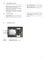
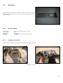
2.2. Detergent Box Group
PREWASH = WATER ENTRY VALVE 1
MAIN = WATER ENTRY VALVE 2
SOFTENER = WATER ENTRY VALVE 1 + VALVE 2
5. After connection is complete, check for leakage by
turning on tap completely.
6. Make sure that water inlet hoses can not become folded,
damaged, stretched or crushed when the washing
machine is in its final position.
7. Mount the water inlet hose to a ¾” threaded water tap.
3. The end of the drain hose can be connected directly to a
drainage stand-pipe or alternatively to a specific
connection point designed for that purpose on the waste
outlet of a sink unit.
4. Do not extend the drain hose or guarantee will be
invalidated.
MAIN
SOFTENER
PREWASH
VALVE1
VALVE2

6
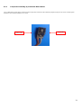
3. Operating Instructions
3.1. R Kontrol Panel
PR
Program selector 16 programs with ON/OFF.
PT
Temperature Adj. Knob
SW1
Switch 1, Start / Pause
SW2
Switch 2, No Spin
SW3
Switch 3, Easy Ironing
LD1
End Led
LD2
Start/ Pause Led
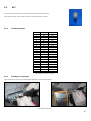
3.2. Program List
Knob Position
Program
Pos1
COTTON90°C
Pos2
COTTON 60°C PRW
Pos3
COTTON 60°C
Pos4
COTTON 40°C
Pos5
ECO WASH
Pos6
QUICK WASH
Pos7
COTTON COLD
Pos8
SYNTHETICS 60°C
Pos9
SYNTHETICS 40°C
Pos10
SYNTHETICS COLD
Pos11
DELİCATE 30'C
Pos12
WOOL 30°C
Pos13
RINSE
Pos14
SPIN
Pos15
DRAIN
PR
SW3
SW2
SW1
LD2
LD1
PT

7
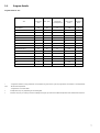
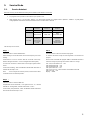
3.3. Program Details
Program Details for 42 lt
42lt
Total time
(min)
Max. T(°C)
Total Water
Consumption (lt)
Max.energy
(kwh)
Number of
Rinse
COTTON90°C
155
83
75
1,96
3
COTTON 60°C PRW
140
57
74
0,89
3
COTTON 60°C
190
57
43
0,85
2
COTTON 40°C
180
40
45
0,82
2
ECO WASH
80
40
43
0,39
2
QUICK WASH
30
25
40
0,16
2
COTTON COLD
110
WIT
56
0,17
3
SYNTHETICS 60°C
84
55
45
0,95
2
SYNTHETICS 40°C
65
40
45
0,53
2
SYNTHETICS COLD
72
WIT
45
0,12
2
DELİCATE 30'C
70
30
56
0,34
3
WOOL 30°C
73
29
52
0,29
3
RINSE
28
WIT
41
0,04
3
SPIN
10
-
-
0,02
-
DRAIN
2
-
-
0,01
-
* : Programme duration ,Energy and Water Consumption are given for the cycles for programmes are started in set temperature.
WIT : Water Inlet Temperature
- : Programmes do not take water
Temperature may vary depending on the heating time
Durations may vary according to wash load (weight and type), tap water and ambient temperature and selected extra functions.

8
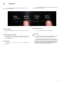
3.5. Child Lock
Press the start-pause and second function button for 3-4
seconds to activate child lock.
Activation Indication
1. The symbol (I6) makes fast blink for indication and is then
fix on.
Child lock during the programme
1. Machine does not respond to any pressing of buttons or
changing position of program knob but option icon makes fast
blink to evoke the user.
In end condition
1. When cycle is finished child lock is automatically
deactivated.
Press the start-pause and second function button for 3-4
seconds to deactivate child lock.
Deactivation Indication
1. Option icon makes fast blink and is then off.
In Error Mode
1. Child lock will be automatically deactivated when error is
detected except NTC (E05) and Voltage (E09) errors.
When E05 and E09 is detected, the child lock will be
deactivated at the end of the program or the user will be able to
deactivate it. On other hand, if the user brings the programme
knob to zero and then any position during these two error
modes, firstly it will show child lock active indication and then
the error indication and it will continue the cycle.

9
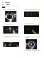
4. Test Mode
4.1. Autotest
* This test is for quick checking of the product. You can not see the
failure codes.
1. Turn the program knob to third program.
2. Press the first function button.
3. While pressing the first function button, turn the program
knob to second program.
4. Release the function button. The button light will be on.
5. Press the first function button again.
6. While pressing the first function button, turn the program
knob to first program. Release the function button and the
autotest starts.
7. When the first function button light flashes, press the
button again. Autotest will enter the second phase.

10

11
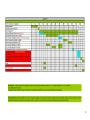
5. Service Mode
5.1. Service Autotest
End users can only see E1-E2-E3-E4. During service autotest, other failures can be seen.
1. Set program knob at position 3 after selection spin speed to max.
2. While pressing the T °C (Sw2) button, keeping T °C (Sw2) button pushed, turn program knob to position 2, release T °C (Sw2) button
change position of the third to second, and remove the T °C button within 1 second.
Selector
Position 1
Selector
Position 2
Selector
Position 3
Result
Result
Result
HEATER ON
PUMP ON
TEST
PROGRAM ON
Comments :
When
entering in
service test,
door will be
locked.
Test is over
Door will be
unlocked,
machine will go
to ENS state.
The test steps are as below ;
Step 1 :
Selector Position 1 will be “HEATER ON”
Before heating it should take water till first level frequency then start
heating.
Heater will be on max. 8 minutes after this 8 minutes if the temp.
doesn’t change more than 2 ° C then it will give NTC failure. (E05).
Or if the NTC connection is broken then it should give again E05 NTC
failure.
At the end of heating, “SAU” visualization should make slow blink to
indicate that the step is over.
Note : If user changes the selector position, machine will do what
is defined for the new selected position.
Step 2 :
Selector Position 2 will be “PUMP ON”
Temperature will be measured, if it is higher than 50 ° C, it should
take 60 sec. cooling water, and then make “Drain + 5 sec.”
At the end of pump activation, “SAU” visualization should make slow
blink to indicate that the step is over.
Step 3 :
Selector Position 3 will be 15 minutes test program.
So machine will make exactly the same algorithm of 15 minutes test
program.
At the end of 15 minutes test program “END” is visualized and door is
unlocked. During test pressing other buttons makes no change.
LD1 Start / Pause button Led → ON
LD6 Wash Phase Led → Off
LD7 Rinse Phase Led → Off
LD8 Spin Phase Led → Off
LD9 Door Lock Led → When the door is unlocked it will be off
LD2, LD3, LD4 → Off
Display → “END”

12
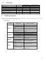
5.2. Failure Codes
Error Indication
Error Number
Indication For User
Indication For Service
Yes/No
Yes/No
Door is not locked
E01
Yes
Yes
Door is unlocked during programme
E01
Yes
Yes
Lack of water
E02
Yes
Yes
Pump failure
E03
Yes
Yes
Overflow
E04
Yes
Yes
NTC or Heater Failure
E05
No
Yes
Motor Failure - 1 (Tachometer open-short circuit or
motor connector is disconnected)
E06
No
Yes
Motor Failure - 2 (triac short circuit)
E08
No
Yes
Electronic Pressure Sensor
E10
No
Yes
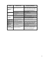
6. Troubleshooting Guide
All repairs which must be done on the machine should be done by authorized agents only. When a repair is required for machine or you are unable
to eliminate the failure with the help of the information given below:
Unplug the machine.
Close the water tap.
FAILURE
PROBABLE CAUSE
METHODS OF ELIMINATION
Machine does not
operate.
It is unplugged.
Insert the plug into the socket.
Fuse is defective.
Change fuse.
Start / Pause button has not been
pressed.
Press the start / pause button.
The program knob is in 0 (off)
status.
Bring the program knob on the desired status.
The door is not shut properly.
Shut the door properly. You should hear the
click.
Child lock is active.
See page 9.
Machine does not
receive water.
Water tap is closed.
Open water tap.
The water inlet hose may be bent.
Check the water inlet hose.
The water inlet hose is obstructed.
Clean the filters of water inlet hose.
The water inlet filter is obstructed.
Clean the valve inlet filters.
The door is not shut properly.
Shut the door properly. You should hear the
click.
Machine is not
draining water.
The drain hose is obstructed or
bent.
Check the drain hose.
The pump filter is obstructed.
Clean the pump filter.
The clothes are not placed inside
the machine in a well-balanced
manner.
Spread the clothes inside the machine in an
orderly and well-balanced manner.
Machine is
vibrating.
The feet of machine are not
adjusted.
Adjust the feet.
Transportation screws are not
removed.
Remove transportation screws.
There is a small amount of clothes
in the device.
It does not prevent operation of the machine.
Excessive amount of clothes are
filled in the machine or the clothes
are not placed in a well-balanced
manner.
Do not exceed the recommended quantity of
clothes and spared clothes in the machine in a
well-balanced manner.

13
FAILURE
PROBABLE CAUSE
METHODS OF ELIMINATION
Excessive foam in
the detergent
drawer
Too much detergent has been
used.
Press the start/pause button. In order to stop
the foam, dilute one table-spoon of softener in
half liter of water and pour it in the detergent
drawer. Press the start/pause button after 5-10
minutes. Arrange the amount of the detergent
properly in the next washing process.
Wrong detergent has been used.
Use only the detergents produced for full
automatic machines.
The washing result
is bad.
Laundry too dirty for the program
you have selected.
Select a suitable program.
The amount of detergent used is
not sufficient.
Use more detergent according to the
detergent.
The washing result
is not good.
Clothes exceeding the maximum
capacity has been filled in machine.
Put the clothes in machine in a manner not to
exceed its maximum capacity.
Water may be hard.
Use the amount of detergent according to the
declaration of the detergent producer.
Distribution of the clothes in
machine is not well-balanced.
Spread the clothes inside the machine in an
orderly and well-balanced manner.
The water is seen
in the drum during
washing.
No failure. The water is at the lower
part of the drum.
There are residues
of detergent on the
clothes.
The pieces of some detergents
which do not dissolve in water may
stick to clothes as white stains.
By calibrating machine for “Rinsing” program,
make an additional rinsing or eliminate the
stains After drying with the help of a brush.
There are grey
stains on the
clothes.
These stains may be caused by oil,
cream or ointment.
In the next washing operation, use the
maximum detergent amount declared by the
detergent producer.
The spinning
process is not done
or starts with delay.
No failure. The unbalanced load
control works in that way.
The unbalanced load control system will try to
distribute clothes in a homogenous manner.
After clothes are distributed, passage to
spinning process will be realized. In the next
washing process, place clothes into the
machine in a well-balanced manner.

14
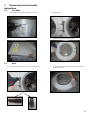
7. Disassembly and Assembly
Instructions
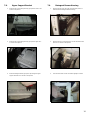
7.1. Top Plate
1. Remove two screws that fix the top-plate at the back.
2. Push the top-plate back and pull it up.
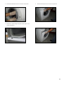
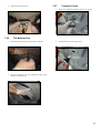
7.2. Door
1. Remove two screws that fix the door. (by using the T25)
T25
2. Pull the door up.
3. Remove screws that fix the door group.
4. Put the door outside plastic with helping screwdriver as it is
shown in the picture.
1
2

15
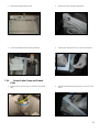
5. Remove the door inside plastic as it is shown in the picture.
6. Remove six screws that fix the door hinge as it is shown in
the picture.
7. Remove the door handle as it is shown in the picture.
8. Remove the door handle pim as it is shown in the picture.

16
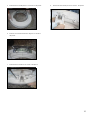
7.3. Tub Bellows Seal
1. First remove the spring wire fixing the tub bellows seal by
using the small size screw driver.
Pull the tub bellows seal as it is shown in the picture.
2. Remove the tub bellows seal-body fixing spring.
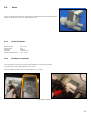
7.4. Detergent Drawer
1. Remove the detergent drawer and pull it up carefully
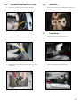
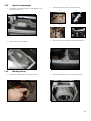
7.5. Control Panel
1. Remove the screw which fix the control panel to the front
panel.

17
2. Remove three screws fixing the control panel.
3. Pull the control panel up.
4. Remove connectors as it is shown in the picture.
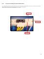
5. Remove the lcd communication cable as it is shown in the
picture.
6. Remove electronic card cover as it is shown in the picture by
using small screw driver.
7. Remove lcd electronic card as it is shown in the picture.

18
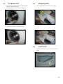
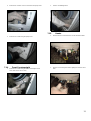
7.6. Kick Plate
1. Remove the right part of the kickplate as it is shown in the
picture.
2. Remove two screws fixing the kickplate.
3. Pull the kickplate left and push it down.
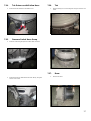
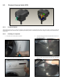
7.7. Front Panel
1. Remove two screws fixing the front panel at the bottom as it
is shown in the picture by using T25
2. Remove two screws fixing the door lock as it is shown in the
pictures.
1
2

19
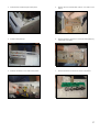
3. Remove the tub bellows seal as it is shown in the pictures.
4. Remove two screws fixing front panel at the upper as it is
shown in the picture.
5. Remove the front panel as it is shown in the pictures.

20
7.8. Upper Support Bracket
1. Remove two screws fixing the body group at the front as it is
shown in the picture.
2. Remove two screws fixing the body group at the upper as it
is shown in the picture.
3. Remove detergent drawer group two clips fixing the upper
support bracket as it is shown in the picture.
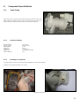
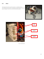
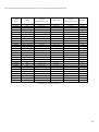
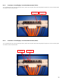
7.9. Detergent Drawer Housing
1. Remove the tub seal clamp by using the pliers, which is
attached to the detergent drawer housing.
2. Remove the four connectors that is connected to the feed
valve as it is shown in the picture.
3. Turn the feed valve counter clockwise slightly to remove.
Page is loading ...
Page is loading ...
Page is loading ...
Page is loading ...
Page is loading ...
Page is loading ...
Page is loading ...
Page is loading ...
Page is loading ...
Page is loading ...
Page is loading ...
Page is loading ...
Page is loading ...
Page is loading ...
Page is loading ...
Page is loading ...
Page is loading ...
Page is loading ...
Page is loading ...
Page is loading ...
Page is loading ...
Page is loading ...
Page is loading ...
-
 1
1
-
 2
2
-
 3
3
-
 4
4
-
 5
5
-
 6
6
-
 7
7
-
 8
8
-
 9
9
-
 10
10
-
 11
11
-
 12
12
-
 13
13
-
 14
14
-
 15
15
-
 16
16
-
 17
17
-
 18
18
-
 19
19
-
 20
20
-
 21
21
-
 22
22
-
 23
23
-
 24
24
-
 25
25
-
 26
26
-
 27
27
-
 28
28
-
 29
29
-
 30
30
-
 31
31
-
 32
32
-
 33
33
-
 34
34
-
 35
35
-
 36
36
-
 37
37
-
 38
38
-
 39
39
-
 40
40
-
 41
41
-
 42
42
-
 43
43


Brandt WFE0605K Owner's manual
- Category
- Washing machines
- Type
- Owner's manual
- This manual is also suitable for
Ask a question and I''ll find the answer in the document
Finding information in a document is now easier with AI
Related papers
Other documents
-
Whirlpool AWSE 6000 User guide
-
VESTEL F4 Series User manual
-
Becken MAQ LAVAR ROUPA WASH UP WMM610WHA Owner's manual
-
-
-
-
-
Bush WMSAE912EB User manual
-
Bush WMSAEINT812W 8KG INT WM WHT User manual
-