Page is loading ...

www.desatech.com
GA3450TA THERMOSTAT BLOWER ACCESSORY
INSTALLATION INSTRUCTIONS
For use on CGCF, VMH26, VMH10, FMH26, and FMH10 Series
Compact Fireplaces and CF26 Series Bayfront Fireplaces
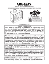
WARNING: Fan accessory must be grounded. Fan
comes with a three-prong, grounding plug as shown in
Figure 1. The plug is your protection against electrical
shock. Plug it into a standard, three-hole, grounded,
outlet. If cord needs replacing, use only a cord with a
three-prong, grounding plug.
NOTICE: Cord length from switch plate assembly to
plug is six feet. Make sure grounded outlet is an ap-
propriate distance from unit.
WARNING: Failure to connect all wires as indicated
may cause electrical shock or personal injury.
CAUTION: Verify proper operation after servicing.
REMOVING UPPER LOUVER ASSEMBLY
To install blower accessory, you must rst remove the upper
louver assembly.
All Models Except CF26 Series
1. Remove 4 brass-plated screws from louver assembly
(see Figure 2). Save these screws.
2. Pull louver assembly straight out from the cabinet. Be
careful not to scratch the paint. Set louver assembly and
screws aside.
Figure 2 - Removing Upper Louver Assembly
Upper Louver
Assembly
Blower Bracket
Mounting Holes
Grounding Plug
Figure 1 - Grounding Plug
Grounded Outlet
STANDARD INSTALLATION
Removing Valve Cover Shield
1. Open bottom louver assembly by swinging the assembly
down (see Figure 3, page 2).
2. Using short Phillips screwdriver, remove screw under
the center of branch support. Rotate valve cover shield
clockwise and slide out. IMPORTANT: Do not remove
shoulder screw on left side of valve cover shield. Slide
valve cover shield off of shoulder screw (see Figure 3,
page 2).
Note: If you do not have a short Phillips screwdriver, the
screen, twigs, and branch support must be removed so a
longer screwdriver may be used. Follow directions in the
owner’s manual for screen and twig removal/installation.
Branch support may be removed by removing 2 screws
on each side of support.

www.desatech.com
108318-01E
2
Installing Blower Assembly
Note: If you are using a mantel with your heater, use the fol-
lowing instructions. If your heater is built-in, see For Built-In
Installation on page 3.
1. Install snap bushings found in hardware kit into both holes
in rear of valve cover shield.
2. Make sure the wire harness is rmly connected to all
terminals on blower bracket assembly.
3. In top of heater cabinet, locate four mounting holes on outer
casing. Align these four holes with those on blower bracket
assembly. Attach blower bracket assembly to outer casing
with 4) #10 screws provided (see Figure 4).
4. Route wire harness through hole in left side of bafe. Pull
wire harness through lower opening above where valve
shield was removed. (See Figure 4.)
5. Insert 4 wire harness into one of the round holes in rear
of valve cover shield and through rectangular hole in front
of shield (see Figure 4).
6. Note the terminal numbers on back of AUTO/OFF/ON
switch. They are numbered 1, 2, and 3. (See Figure 4).
7. Connect red wire on blower harness to switch position 3.
Connect blue wire to switch position 1.
8. Connect green wire to green wire of power cord. Connect
white wire to white wire of power cord.
9. Install switch plate on valve cover shield with 2) #10 screws
provided (see Figure 5). Reinstall valve cover shield. Route
power cord out of cabinet by inserting it through bushing
on outer casing (see Figure 4). Plug fan kit into 120-Volt
grounded power supply and test operation.
Note: When switch is in the AUTO position, the fan will
start after heater has run for a few moments. Fan will
continue to run for several moments after heater has been
turned off. When switch is in the ON position, the fan will
run until turned to OFF.
Reinstall upper louver assembly (see Figure 2, page 1)
and close lower louver door.
Bottom Louver
Assembly
Remove
Screw
Valve Cover
Shield
Shoulder
Screw
Figure 3 - Removing Valve Cover Shield
Branch Support
Snap
Bushings
3
2
1
Wire
Harness
Figure 4 - Installing Blower Bracket Assembly
Blower Bracket
Assembly
Screw
Power
Cord
Valve
Cover
Shield
Box Cover
Wire
Harness
Switch Plate
Switch
Bafe
Wiring Routing
Hole in Bafe
Blue
Red
Figure 5 - Installing Switch Plate to Valve Cover Shield
Valve Cover
Shield
Switch
Plate
Screw

www.desatech.com
108318-01E
3
FOR BUILT-IN INSTALLATION
WARNING: A licensed electrician must connect the
wiring harness to electrical supply following all local
codes. Electrician must provide a clamp on the box
cover to secure the wiring. Wiring should be routed
through the bushing in the hole on the outer casing
of heater.
Follow instructions Removing Valve Cover Shield (page 1),
then
1. Install a snap bushing found in hardware kit into one of the
holes found rear of valve cover shield. The other hole is
for a strain relief clamp (not supplied) to secure incoming
electrical supply.
2. Follow steps 2 through 4 in Installing Blower Assembly,
page 2. Also remove black wire from middle switch ter-
minal 2.
3. Remove black plastic strain relief and power cord from
switch plate. The power cord supplied will not be used in
built-in installations. Pop in the plastic snap bushing found
in hardware kit into the hole left by supply cord/strain
relief.
4. A licensed electrician must follow the wiring diagram to
connect incoming electrical supply to fan kit wiring har-
ness (see Figure 7).
5. Reinstall valve cover shield.
6. Test to make sure blower is working properly.
7. Reinstall upper louver assembly (see Figure 2, page 1)
and close lower louver.
3
2
1
Figure 6 - Installing Blower Bracket Assembly
Blower Bracket
Assembly
Screw
Wire
Harness
Power
Cord
Valve
Cover
Shield
Box Cover
Wire
Harness
Switch Plate
Switch
Clamp Connector
(not included)
Outlet
Receptacle
Blue
Red
EXTENSION CORD
Use extension cord if needed. The cord must have a three-
prong, grounding plug and a three-hole receptacle. Make sure
cord is in good shape. It must be heavy enough to carry the
current needed. An undersized cord will cause a drop in line
voltage. This will result in loss of power and overheating. Use
a No. 16 AWG cord for lengths less than 50 feet.
Figure 7 - Wiring Diagram Decal
101584-06
WARNING: Never attempt to service heater while it is
plugged in, operating, or hot. Burns and electrical shock
could result. Only a qualied service person should service
or repair heater.
If any of the original wire as supplied with the appliance must be replaced,
original replacements must be used. DESA part no. 104015-01 (105°C)
for power cord, and DESA part no. 103968-01 (200°C) for blower.
WARNING: Label all wires prior to disconnection when
servicing controls. Wiring errors can cause improper and dan-
gerous operation. Verify proper operation after servicing.
ADVERTENCIA: nunca intente reparar el calentador mientras
esté conectado, en funcionamiento o caliente. Puede sufrir
quemaduras o electrocución. Sólo una persona de servicio
capacitada debe reparar el calentador o darle servicio.
En caso que se deba reemplazar alguno de los cables suministrados
originalmente con el calentador, utilice únicamente repuestos originales.
Parte DESA número 104015-01 (105°C) para el cable de alimentación
y parte DESA número 103968-01 (200°C) para el ventilador.
ADVERTENCIA: marque todos los cables antes de
desconectarlos. Los errores en el cableado pueden ocasionar
funcionamiento errático y peligroso. Después de dar servicio
al calentador compruebe que éste funcione correctamente.
Red
Red
Fan Switch
(Auto/Off/On)
Blue
Blue
Thermostat
Switch
(N.O.)
Green
White
Green
White
On
110/115
V.A.C.
Blower
Motor
Black
Off
1
2
3
Auto
120 Vac.(V C.A.) 60 Hz. .53 AmpsV C.A.) 60 Hz. .53 Amps
DESA Heating, LLC, Bowling Green, KY
Rojo
Rojo
Interruptor del ventilador
(automático/apagado/encendido)
Azul
Azul
Interruptor de
sensor de
temperatura
(N.O.)
Verde
Blanco
Verde
Blanco
Encendido
110/115
V.A.C. (V.C.A.)
Motor
del ventilador
Negro
Apagado
1
2
3
Automático

O
FF
O
N
OPERATING FAN
This blower has three settings: ON, OFF, and AUTO. In the
ON position, the blower will operate constantly. In the OFF
position, the blower will not operate. In the AUTO position,
the blower will start when the thermostat senses a sufcient
increase in rebox temperature.
Note: Your replace and thermostat blower will not turn on and
off at the same time. The replace may run for several minutes
before the blower turns on. After the heater modulates to the
pilot position, the blower will continue to run. The blower will
shut off after the rebox temperature decreases.
Note: It is safe to operate replace with blower turned off.
However, the blower helps distribute heated air from the
replace.
Figure 8 - Auto/Off/On Switch
Auto/Off/On Switch
DESA Heating, LLC
2701 Industrial Drive
P.O. Box 90004
Bowling Green, KY 42102-9004
www.desatech.com
108318-01
Rev E
09/07
/