Whirlpool KGCC506RBL Installation guide
- Category
- Cookers
- Type
- Installation guide

INSTALLATION INSTRUCTIONS
30" (76.2 CM) AND 36" (91.4 CM)
GAS BUILT-IN COOKTOP
INSTRUCTIONS D'INSTALLATION
DE LA TABLE DE CUISSON À GAZ ENCASTRÉE DE
30" (76,2 CM) ET 36" (91,4 CM)
Table of Contents/Table des matières
COOKTOP SAFETY........................................................................2
INSTALLATION REQUIREMENTS................................................3
Tools and Parts ............................................................................3
Location Requirements................................................................3
Electrical Requirements ...............................................................5
Gas Supply Requirements...........................................................5
INSTALLATION INSTRUCTIONS..................................................7
Prepare Cooktop for Installation..................................................7
Install Cooktop ........
.....................................................................7
Make Gas Connection .................................................................8
Attach Cooktop to Countertop ....................................................9
Complete Installation .................................................................10
WIRING DIAGRAMS.....................................................................11
SÉCURITÉ DE LA TABLE DE CUISSON ....................................13
EXIGENCES D'INSTALLATION...................................................14
Outillage et pièces......................................................................14
Exigences d'emplacement.........................................................14
Spécifications électriques ..........................................................16
Spécifications de l'alimentation en gaz .....................................16
INSTRUCTIONS D'INSTALLATION.............................................18
Préparation de la table de cuisson pour l'installation................18
Installation de la table de cuisson..............................................18
Raccordement au gaz................................................................20
Fixation de la table de cuisson au plan de travail......................21
Achever l'installation ..................................................................22
SCHÉMAS DE CÂBLAGE ............................................................23
W10526074B
IMPO
RTANT:
Installer:
Leave installation instructions with the homeowner.
Home
owner: Keep installation instructions for future reference.
IMPO
RTANT :
Installateur :
Remettre les instructions d'installation au propriétaire.
P
ropriétaire : Conserver les instructions d'installation pour référence ultérieure.

2
COOKTOP SAFETY
You can be killed or seriously injured if you don't immediately
You
can be killed or seriously injured if you don't
follow
All safety messages will tell you what the potential hazard is, tell you how to reduce the chance of injury, and tell you what can
happen if the instructions are not followed.
Your safety and the safety of others are very important.
We have provided many important safety messages in this manual and on your appliance. Always read and obey all safety
messages.
This is the safety alert symbol.
This symbol alerts you to potential hazards that can kill or hurt you and others.
All safety messages will follow the safety alert symbol and either the word “DANGER” or “WARNING.”
These words mean:
follow instructions.
instructions.
DANGER
WARNING
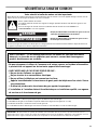
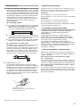
WARNING: If the information in this manual is not followed exactly, a fire or explosion
may result causing property damage, personal injury or death.
– Do not store or use gasoline or other flammable vapors and liquids in the vicinity of this
or any other appliance.
– WHAT TO DO IF YOU SMELL GAS:
•
Do not try to light any appliance.
•
Do not touch any electrical switch.
•
Do not use any phone in your building.
•
Immediately call your gas supplier from a neighbor's phone. Follow the gas supplier's
instructions.
•
If you cannot reach your gas supplier, call the fire department.
– Installation and service must be performed by a qualified installer, service agency or
the gas supplier.
WARNING: Gas leaks cannot always be detected by smell.
Gas suppliers recommend that you use a gas detector approved by UL or CSA.
For more information, contact your gas supplier.
If a gas leak is detected, follow the “What to do if you smell gas” instructions.
IMPORTANT: Do not install a ventilation system that blows air downward toward this gas cooking appliance. This type of
ventilation system may cause ignition and combustion problems with this gas cooking appliance resulting in personal injury or
unintended operation.

3
INSTALLATION REQUIREMENTS
Tools and Parts
Gather the required tools and parts before starting installation.
Tools needed
Parts supplied
■ Gas pressure regulator
■ Burner grates
■ Burner caps
■ Clamping brackets (2)
■ 2¹⁄₂" (6.4 cm) clamping screws (2)
Parts needed
Check local codes and consult gas supplier. Check existing gas
supply and electrical supply. See “Electrical Requirements” and
“Gas Supply Requirements” sections.
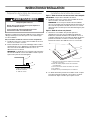
Location Requirements
IMPORTANT: Observe all governing codes and ordinances. Do
not obstruct flow of combustion and ventilation air.
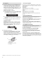
■ It is the installer’s responsibility to comply with installation
clearances specified on the model/serial rating plate. The
model/serial rating plate is located on the underside of the
cooktop base.
■ To eliminate the risk of burns or fire by reaching over heated
surface units, cabinet storage space located above the
surface units should be avoided. If cabinet storage is to be
provided, the risk can be reduced by installing a range hood
that projects horizontally a minimum of 5" (12.7 cm) beyond
the bottom of the cabinets.
■ The cooktop should be installed in a location away from
strong draft areas, such as windows, doors and strong
heating vents or fans.
■ All openings in the wall or floor where cooktop is to be
installed must be sealed.
■ Cabinet opening dimensions that are shown must be used.
Given dimensions are minimum clearances.
■ Grounded electrical supply is required. See “Electrical
Requirements” section. Proper gas supply connection must
be available. See “Gas Supply Requirements” section.
■ The cooktop is designed to hang from the countertop by its
side or rear flanges.
■ The gas and electric supply should be located as shown in
“Cabinet Dimensions” section so that they are accessible
without requiring removal of the cooktop.
■ Provide cutout in right rear corner of cutout enclosure as
shown to provide clearance for gas inlet, power supply cord,
and to allow the rating label to be visible.
IMPORTANT: To avoid damage, check with your builder or
cabinet supplier to make sure that the materials used will not
discolor, delaminate or sustain other damage.
Mobile Home - Additional Installation Requirements
The installation of this cooktop must conform to the
Manufactured Home Construction and Safety Standard, Title 24
CFR, Part 3280 (formerly the Federal Standard for Mobile Home
Construction and Safety, Title 24, HUD Part 280). When such
standard is not applicable, use the Standard for Manufactured
Home Installations, ANSI A225.1/NFPA 501A or with local codes.
In Canada, the installation of this cooktop must conform with the
current standards CAN/CSA-A240-latest edition, or with local
codes.
In the State of Massachusetts, the following installation instructions apply:
■ Installations and repairs must be performed by a qualified or licensed contractor, plumber, or gasfitter qualified or licensed by
the State of Massachusetts.
■ If using a ball valve, it shall be a T-handle type.
■ A flexible gas connector, when used, must not exceed 3 feet.
■ Tape measure
■ Screwdriver
■ ¹⁵⁄₁₆" combination wrench
■ Pipe wrench
■ Wrench or pliers
■ Marker or pencil
■ Pipe-joint compound
resistant to LP gas
■ Noncorrosive leak-detection
solution
A. Model/serial rating plate
A

4
Product Dimensions
Metal Cooktops
Straight-edge glass cooktops
Curved-edge glass cooktops
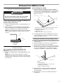
Cabinet Dimensions
IMPORTANT: If installing a range hood or microwave hood
combination above the cooktop, follow the range hood or
microwave hood combination installation instructions for
dimensional clearances above the cooktop surface.
NOTES: After making the countertop cutout, some installations
may require notching down the base cabinet side walls to clear
the cooktop base. To avoid this modification, use a base cabinet
with sidewalls wider than the cutout.
If cabinet has a drawer, a 4" (10.2 cm) depth clearance from the
countertop to the top of the drawer (or other obstruction) in base
cabinet is required. The drawer depth may need to be shortened
to avoid interfering with the regulator.
A. 31⁷⁄₁₆" (79.8 cm) on 30" (76.2 cm) models,
37⁹⁄₁₆" (95.4 cm) on 36" (91.4 cm) models
B. 21¹⁄₄" (53.4 cm)
C. 2⁷⁄₈" (7.3 cm)
A. 20⁵⁄₁₆" (51.5 cm)
B. 30³⁄₁₆" (76.8 cm) on 30" (76.2 cm) models,
36⁷⁄₁₆" (92.5 cm) on 36" (91.4 cm) models
C. 2⁷⁄₈" (7.3 cm)
A. 21¹⁄₈" (53.7 cm)
B. 30⁵⁄₁₆" (77.0 cm) on 30" (76.2 cm) models,
36⁵⁄₁₆" (92.3 cm) on 36" (91.4 cm) models
C. 2⁷⁄₈" (7.3 cm)
A
B
C
C
A
B
A
B
C
A. 30" (76.2 cm) on 30" models; 36" (91.4 cm) on 36" models
B. Combustible area above countertop (shown by dashed box
above)
C. 30
" (76.2 cm) minimum clearance between top of cooktop
platform and bottom of uncovered wood or metal cabinet (24"
[61 cm] minimum clearance if bottom of wood or metal
cabinet is covered by not less than ¹⁄₄
" [0.6 cm] flame retardant
millboard covered with not less than No. 28
MSG sheet steel, 0.015
" [0.04 cm] stainless steel, or
0.024
" [0.06 cm] aluminum or 0.020" [0.05 cm] copper)
D. 13
" (33 cm) recommended upper cabinet depth
E. 2¹⁄₈
" (5.4 cm)
F. 19
" (48.3 cm)
G. 18" (45.7 cm) minimum clearance from upper cabinet to
countertop within minimum horizontal clearances to cooktop
H. Grounded outlet - locate within 24" (61 cm) of right rear corner
of cutout
I. 29" (73.7 cm) on 30" models; 35¼" (89.5 cm) on 36" models
J. 8³⁄₈" (21.3 cm) minimum distance to nearest left and right side
combustible surface
K. 2⁷⁄₈" (7.3 cm) minimum distance to rear combustible surface
L. Gas line opening - Wall: anywhere 5" (12.7 cm) below
underside of countertop. Cabinet floor: anywhere within
6" (15.2 cm) of rear wall is recommended
M. 24" (61 cm) minimum countertop depth is required
B
D
A
C
E
F
H
I
J
G
K
L
M
J

5
Electrical Requirements
IMPORTANT: The cooktop must be electrically grounded in
accordance with local codes and ordinances, or in the absence
of local codes, with the National Electrical Code, ANSI/NFPA 70
or Canadian Electrical Code, CSA C22.1.
This cooktop is equipped with an electronic ignition system that
will not operate if plugged into an outlet that is not properly
polarized.
If codes permit and a separate ground wire is used, it is
recommended that a qualifi
ed electrical installer determine that
the ground path is adequate.
A copy of the above code standards can be obtained from:
National Fire Protection Association
1 Batterymarch Park
Quincy, MA 02169-7471
CSA International
8501 East Pleasant Valley Road
Cleveland, OH 44131-5575
A 120 volt, 60 Hz, AC only, 15-amp, fused electrical circuit is
required. A time-delay fuse or circuit breaker is also
recommended. It is recommended that a separate circuit
serving only this cooktop be provided.
Electronic ignition systems operate within wide voltage limits,
but proper grounding and polarity are necessary. Check that
the outlet provides 120-volt power and is correctly grounded.
The wiring diagrams are provided with this cooktop. See
“Wiring Diagrams” section.
Gas Supply Requirements
Observe all governing codes and ordinances.
IMPORTANT: This installation must conform with all local codes
and ordinances. In the absence of local codes, installation must
conform with American National Standard, National Fuel Gas
Code ANSI Z223.1 - latest edition or CAN/CGA B149 - latest
edition.
IMPORTANT: Leak testing of the cooktop must be conducted
according to the manufacturer’s instructions.
Type of Gas
Natural Gas:
This cooktop is factory set for use with Natural gas. If
converting to LP gas, see the following “LP Gas Conversion”
section. The model/serial rating plate located on the
underside of the cooktop base has information on the types
of gas that can be used. If the types of gas listed do not
include the type of gas available, check with the local gas
supplier.
LP Gas Conversion:
Conversion must be done by a qualified service technician.
No attempt shall be made to convert
the cooktop from the gas
specified on the model/serial rating plate for use with a different
gas without consulting the serving gas supplier. See the Gas
Conversion instructions provided in the package containing
literature.
Electrical Shock Hazard
Plug into a grounded 3 prong outlet.
Do not remove ground prong.
Do not use an adapter.
Do not use an extension cord.
Failure to follow these instructions can result in death,
fire, or electrical shock.
WARNING
WARNING
Explosion Hazard
Use a new CSA International approved gas supply line.
Install a shut-off valve.
Securely tighten all gas connections.
If connected to LP, have a qualified person make sure
gas pressure does not exceed 14" (36 cm) water
column.
Examples of a qualified person include:
licensed heating personnel,
authorized gas company personnel, and
authorized service personnel.
Failure to do so can result in death, explosion, or fire.

6
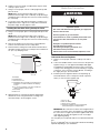
Gas Supply Line
■ Provide a gas supply line of ³⁄₄" (1.9 cm) rigid pipe to the
cooktop location. A smaller size pipe on longer runs may
result in insufficient gas supply. Pipe-joint compounds that
resist the action of LP gas must be used. Do not use
TEFLON
®†
tape. With LP gas, piping or tubing size should be
½" minimum. Usually, LP gas suppliers determine the size
and materials used in the system.
Flexible metal appliance connector:
■ If local codes permit, use a ¹⁄₂" or ³⁄₄" I.D. flexible stainless
steel tubing gas connector, designed by CSA to connect
the cooktop to the rigid gas supply line.
■ A ½" male pipe thread is needed for connection to the
female pipe threads of the inlet to the cooktop pressure
regulator.
■ Do not kink or damage the flexible metal tubing when
moving the cooktop.
Rigid pipe connection:
The rigid pipe connection requires a combination of pipe
fittings to obtain an in-line connection to the cooktop. The
rigid pipe must be level with the cooktop connection. All
strains must be removed from the supply and fuel lines so
cooktop will be level and in line.
■ Must include a shutoff valve:
The supply line must be equipped with a manual shutoff
valve. This valve should be located in the same room but
external to the cooktop opening, such as an adjacent
cabinet. It should be in a location that allows ease of opening
and closing. Do not block access to shutoff valve. The valve
is for turning on or shutting off gas to the cooktop.
Gas Pressure Regulator
The gas pressure regulator supplied with this cooktop must be
used. The inlet pressure to the regulator should be as follows for
proper operation:
Natural Gas:
Minimum pressure: 5" (12.7 cm) WCP
Maximum pressure: 7" to 14" (17.8 cm to 35.5 cm) WCP
LP Gas:
Minimum pressure: 11" (27.9 cm) WCP
Maximum pressure: 14" (35.5 cm) WCP
Contact local gas supplier if you are not sure about the inlet
pressure.
Burner Input Requirements
Input ratings shown on the model/serial rating plate are for
elevations up to 2,000 ft (609.6 m).
For elevations above 2,000 ft (609.6 m), ratings are reduced at a
rate of 4% for each 1,000 ft (304.8 m) above sea level (not
applicable for Canada).
For elevations above 6,560 ft (1999.5 m) a high altitude kit is
needed to avoid any reduced power output. See separate LP gas
conversion instructions sheet.
Gas Supply Pressure Testing
Gas supply pressure for testing regulator must be at least
1" water column pressure above the manifold pressure shown on
the model/serial rating plate.
Line pressure testing above ½ psi gauge (14" WCP)
The cooktop and its individual shutoff valve must be
disconnected from the gas supply piping system during any
pressure testing of that system at test pressures in excess of
½ psi (3.5 kPa).
Line pressure testing at ½ psi gauge (14" WCP) or lower
The cooktop must be isolated from the gas supply piping system
by closing its individual manual shutoff valve during any pressure
testing of the gas supply piping system at test pressures equal to
or less than ½ psi (3.5 kPa).
A. Gas supply line
B. Shutoff valve “open” position
C. To cooktop
†®TEFLON is a registered trademark of E.I. Du Pont De Nemours and Company.
A
B
C

7
INSTALLATION INSTRUCTIONS
Prepare Cooktop for Installation
Decide on the final location for the cooktop. Avoid drilling into or
severing existing wiring during installation.
On Glass Cooktop models only:
1. Using 2 or more people, place the cooktop upside down on a
covered surface.
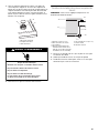
2. Remove foam strip from the package containing literature.
Remove backing from foam strip. Apply foam strip adhesive-
side down around bottom of cooktop, flush with edge.
NOTE: The foam strip keeps debris away from the underside
of the cooktop and helps the cooktop to sit flat on uneven
counters.
Install Cooktop
Style 1: Cooktop over undercounter built-in oven
IMPORTANT: Clamping brackets should not be used.
1. Using 2 or more people, place cooktop right side up into the
cutout.
NOTE: Make sure that the front edge of the cooktop is
parallel to the front edge of the countertop. If repositioning is
needed, lift entire cooktop up from cutout to avoid scratching
the countertop.
Style 2: Cooktop over cabinets
1. Determine whether your cabinet construction provides
clearance for installing clamping brackets at cooktop base
ends. This is the recommended location. Clamping brackets
can be installed on the front and back of cooktop base
bottom, if necessary.
2. The clamping brackets can be installed before or after the
cooktop is placed into the cutout. Complete the following
steps for the option you choose.
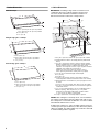
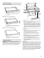
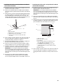
Installing Brackets Before Placing Cooktop in Cutout
1. Using 2 or more people, place the cooktop upside down on a
covered surface.
2. Remove the attachment screws for the selected bracket
locations from the bottom of the cooktop base.
3. Select bracket mounting holes that will allow the bracket to
extend far enough out from the cooktop for the installation of
2½" (6.4 cm) clamping screws. See “Attach Cooktop to
Countertop” for illustration of clamping screw installation.
4. Attach brackets to cooktop base bottom with bracket
attachment screws using the bracket mounting holes
selected in Step 2.
5. Rotate brackets so they do not extend beyond edge of
cooktop base.
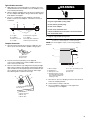
A. Cooktop base
B. Foam strip
C. Cooktop
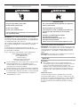
WARNING
Excessive Weight Hazard
Use two or more people to move and install cooktop.
Failure to do so can result in back or other injury.
A
B
C
A. Attachment screw holes for optional front and back location.
B. Clamping bracket (end locations recommended)
C. Cooktop base bottom
D. Attachment screw
E. Attachment screw location (recommended)
A. Clamping bracket
B. Recommended attachment screw location
C. Clamping screw location
D. Edge of cooktop base bottom
A
B
C
D
E
A
B
C
D

8
6. Tighten screws just enough to hold brackets in place when
cooktop is put in cutout.
7. Using 2 or more people, turn the cooktop right side up and
place in cutout.
NOTE: Make sure that the front edge of the cooktop is
parallel to the front edge of the countertop. If repositioning is
needed, lift entire cooktop up from cutout to avoid scratching
the countertop.
8. Loosen the screws and rotate the brackets so that they are
perpendicular to the edge of the cooktop base and extend
beyond its edge. Securely tighten screws.
Installing Brackets After Placing Cooktop in Cutout
1. Using 2 or more people, place cooktop right side up into the
cutout.
NOTE: Make sure that the front edge of the cooktop is
parallel to the front edge of the countertop. If repositioning is
needed, lift entire cooktop up from cutout to avoid scratching
the countertop.
2. Remove the attachment screws for the selected bracket
locations from the bottom of the cooktop base.
3. Select bracket mounting holes that will allow the bracket to
extend far enough out from the cooktop for the installation of
2½" (6.4 cm) clamping screws.
4. Attach brackets to cooktop base bottom with bracket
attachment screws using the bracket mounting holes
selected in Step 3. Securely tighten screws.
Make Gas Connection
To Assemble Pressure Regulator:
1. Using 2 or more people, stand the cooktop on its side or
back.
2. Connect the flexible stainless steel connector to the pressure
regulator using a ½" male pipe thread adapter and nipple.
A combination of pipe fittings must be used to connect the
cooktop to the existing gas line. Shown following is a typical
connection. Your connection may be different, according to
the supply line type, size and location.
3. Install the pressure regulator with the arrow pointing up
toward the bottom of the cooktop base and in a position
where you can reach the regulator cap.
IMPORTANT: All connections must be wrench-tightened. Do
not make connections to the gas regulator too tight. Making
the connections too tight may crack the regulator and cause
a gas leak. Do not allow the regulator to turn on the pipe
when tightening fittings.
Use only pipe-joint compound made for use with Natural and LP
gas.
Do not use TEFLON
®
tape. You will need to determine the fittings
required depending on your installation.
A. Cooktop
B. Cooktop base
C. Attachment screw
D. Clamping bracket (extends far enough beyond
cooktop base to allow installation of clamping
screws)
E. 2½" (6.4 cm) clamping screw (to be installed in
“Attach Cooktop to Countertop”)
F. Countertop
G. Foam seal
A
B
C
D
E
F
G
A. Access cap
B. Rear of cooktop
C. Gas pressure regulator
D. Up arrow. Regulator must be installed with
arrow pointing up to cooktop bottom.
WARNING
Explosion Hazard
Use a new CSA International approved gas supply line.
Install a shut-off valve.
Securely tighten all gas connections.
If connected to LP, have a qualified person make sure
gas pressure does not exceed 14" (36 cm) water
column.
Examples of a qualified person include:
licensed heating personnel,
authorized gas company personnel, and
authorized service personnel.
Failure to do so can result in death, explosion, or fire.
A
B
C
D

9
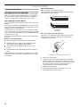
Typical flexible connection
1. Apply pipe-joint compound made for use with LP gas to the
smaller thread ends of the flexible connector adapters (see G
in the following illustration).
2. Attach 1 adapter and nipple to the gas pressure regulator and
the other adapter and nipple to the gas shutoff valve. Tighten
both adapters and nipples.
3. Use a ¹⁵⁄₁₆" combination wrench and pliers to attach the
flexible connector to the adapters. Check that connector is
not kinked.
Complete Connection
1. Open the manual shutoff valve in the gas supply line. The
valve is open when the handle is parallel to the gas pipe.
2. Test all connections by brushing on an approved
noncorrosive leak-detection solution. Bubbles will show a
leak. Correct any leak found.
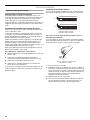
3. Remove surface burner caps and grates from parts package.
Align notches in burner caps with pins in burner base. Burner
caps should be level when properly positioned. If burner caps
are not properly positioned, surface burners will not light.
Place burner grates over burners and caps.
4. Plug into a grounded 3 prong outlet.
Attach Cooktop to Countertop
NOTE: This section applies only if you are using clamping
brackets.
1. Place the 2½" (6.4 cm) clamping screws into the outermost
hole in the clamping bracket.
2. Check that the cooktop is still level.
3. Use a screwdriver to tighten the screws against the
countertop. Do not overtighten.
A.
³⁄₈
" nipple
B.
³⁄₈
" adapter
C. Flexible connector
D. ½" nipple
E. Gas pressure regulator
F. ½" adap ter
G. Use pipe-joint compound.
H. Manual gas shutoff valve
A. Closed valve
B. Open valve
A. Igniter electrode
B. Burner cap
C. Burner base
A
B
C
D
E
G
F
H
A
B
A
B
C
A. Glass cooktop
B. Cooktop base
C. Attachment screw
D. Clamping bracket (extends
far enough beyond cooktop
base to allow installation of
clamping screws)
E. 2½" (6.4 cm) clamping screw
F. Coun te rt op
G. Foam seal
Electrical Shock Hazard
Plug into a grounded 3 prong outlet.
Do not remove ground prong.
Do not use an adapter.
Do not use an extension cord.
Failure to follow these instructions can result in death,
fire, or electrical shock.
WARNING
A
B
C
D
E
F
G

10
Complete Installation
Electronic Ignition System
Initial lighting and gas flame adjustments
Surface burners use electronic igniters in place of standing pilots.
When the cooktop control knob is turned to the “LITE” position,
the system creates a spark to light the burner. This sparking
continues, as long as the control knob is turned to “LITE.”
Check Operation of Surface Burners
Push in and turn the surface burners control knobs to the “LITE”
position.
The surface burner flame should light within 4 seconds. The first
time a surface burner is lighted it may take longer than 4 seconds
to light because of air in the gas line.
Check the flame on “HI” for a blue color. It should be clean and
soft in character. No yellow tip, blowing or lifting of flame should
occur. Occasional orange flashes are normal and reflect different
elements in the air or gas.
After verifying the proper burner operation, turn the control knobs
to “OFF.”
If burners do not light properly:
■ Turn surface burner control knob to the “OFF” position.
■ Check that the power supply cord is plugged in and the
circuit breaker has not tripped or the fuse blown.
■ Check that the gas shutoff valves are set to the “open”
position.
■ Check that burner caps are properly positioned on burner
bases.
Recheck operation of surface burners. If a burner does not light
at this point, contact your dealer or authorized service company
for assistance.
Check Flame Height
Adjust the height of surface burner flames.
The surface burner “low” flame should be a steady blue flame
approximately ¼" (0.64 cm) high.
If the “low” flame needs to be adjusted:
The flame can be adjusted using the adjustment screw in the
center of the valve stem. The valve stem is located directly
underneath the control knob.
1. Remove the control knob.
2. Hold the knob stem with a pair of pliers. Use a small flat-
blade screwdriver to turn the screw located in the center of
the control knob stem until the flame is the proper size. Turn
the screw clockwise to decrease the flame height or
counterclockwise to increase the flame height.
3. Replace the control knob.
4. Test the flame by turning the control from “LO” to “HI,”
checking the flame at each setting.
A. Low flame
B. High flame
A. Adjustment screw in center of valve stem
A
B
A

11
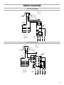
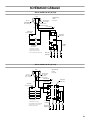
WIRING DIAGRAMS
On 30" (76.2 cm) models
On 36" (91.4 cm) models
Plug
120 VAC 60 Hz
1 Phase
15 or 20 AMP
Neutral
⁵⁄₁₆
" Wide Blade
Ground Round Blade
G or G/Y
GND
W
W
Line
¼" Wide Blade
BK
BK
Connect
.250 Terminals
Valve
Switches
Switches On Valves
Electric Circuit
Closed When Knob Is
Rotated 55˚ to 95˚
Counterclockwise
From OFF
Igniter
Electrodes
Spark
Module
Y or BR
(4) PLCS
Plug
120 VAC 60 Hz
1 Phase
15 or 20 AMP
Neutral
⁵⁄₁₆
" Wide Blade
Ground Round Blade
G or G/Y
G or G/Y
Line
¼" Wide Blade
BK
W
Connect
.250 Terminals
BK
Valve
Switches
Switches On Valves
Electric Circuit
Closed When Knob Is
Rotated 55˚ to 95˚
Counterclockwise
From OFF
Igniter
Electrodes
Y or BR
(4) PLCS
5
4
3
2
GND
L1
N
1
GND
GND
Spark
Module
Page is loading ...
Page is loading ...
Page is loading ...
Page is loading ...
Page is loading ...
Page is loading ...
Page is loading ...
Page is loading ...
Page is loading ...
Page is loading ...
Page is loading ...
Page is loading ...
Page is loading ...
-
 1
1
-
 2
2
-
 3
3
-
 4
4
-
 5
5
-
 6
6
-
 7
7
-
 8
8
-
 9
9
-
 10
10
-
 11
11
-
 12
12
-
 13
13
-
 14
14
-
 15
15
-
 16
16
-
 17
17
-
 18
18
-
 19
19
-
 20
20
-
 21
21
-
 22
22
-
 23
23
-
 24
24


Whirlpool KGCC506RBL Installation guide
- Category
- Cookers
- Type
- Installation guide
Ask a question and I''ll find the answer in the document
Finding information in a document is now easier with AI
in other languages
Related papers
-
Whirlpool KGCC566RBL User manual
-
Whirlpool W3CG3014XS Installation Instructions (417.53 KB)
-
Whirlpool KGCK346BSS0 Installation guide
-
-
-
-
-
-
-
Other documents
-
JennAir JGC7636BS Installation guide
-
Amana AGC6356KFB01 Installation guide
-
-
-
Maytag G7CG3665XS Installation Instructions Manual
-
Bauknecht G7CG3665XS Owner's manual
-
-
-
-
KitchenAid JGD3430GS Installation guide