Page is loading ...
September
1999
Processes
~
MIG
(GMAW)
Welding
Flux
Cored
(FCAW)
Welding
Description
Arc
Welding
Power
Source
and
Wire
Feeder
Millermatic
300
OM-1317
Miller
The
Power
ofBIue.
185
529L
.
/
/
/
-
Visit
ouc
website
at
www.MillerWelds.com
OWNERS
MANUAL
MANUAL
DEL
OPERADOR
(cuando
disponible)
sigue
al
manual
en
inglØs

L~.
Working
as
hard
as
you
do
..
1
-
every
power
source
from
.Milleris
backed
by
the
most
hassle-free
warranty
in
the:.
business.
:
.
From
Miller
to
You
Thank
you
and
congratulations
on
choosing
Miller.
Now
you
can
get
the
job
done
and
get
it
done
right.
We
know
you
dont
have
time
to
do
it
any
other
way.
Thats
why
when
Niels
Miller
first
started
building
arc
welders
in
1929,
he
made
sure
his
products
offered
long-lasting
value
and
superior
quality.
Like
you,
his
customers
couldnt
afford
anything
less.
Miller
products
had
to
be
more
than
the
best
they
could
be.
They
had
to
be
the
best
you
could
buy.
Today,
the
people
that
build
and
sell
Miller
products
continue
the
tradition.
Theyre
just
as
committed
to
providing
equipment
and
service
that
meets
the
high
standards
of
quality
and
value
established
in
1929.
This
Owners
Manual
is
designed
to
help
you
get
the
most
out
of
your
Miller
products.
Please
take
time
to
read
the
Safety
precautions.
They
will
help
you
protect
yourself
against
potential
hazards
on
the
worksite.
Weve
i~ItIIIIw
REGISTERED
QUALITY
SYSTEM
Miller
is
the
first
welding
equipment
manufacturer
in
the U.S.A.
to
be
registered
to
the
ISO
9001
Quality
System
Standard.
made
installation
and
operation
quick
and
easy.
With
Miller
you
can
count
on
years
of
reliable
service
with
proper
maintenance.
And
if
for
some
reason
the
unit
needs
repair,
theres
a
Troubleshooting
section
that
will
help
you
figure
out
what
the
problem
is.
The
parts
list
will
then
help
you
to
decide
which
exact
part
you
may
need
to
fix
the
problem.
Warranty
and
service
information
for
your
particular
model
are
also
provided.
s.~
.\
~
\
Miller
Electric
manufactures
a
full
line
of
welders
and
welding
related
equipment.
For
information
on
other
quality
Miller
products,
contact
your
local
Miller
distributor
to
receive
the
latest
full
line
catalog
or
individual
catalog
sheets.
To
locate
your
nearest
distributor
call
1-800-4-A-Miller.
Miller
offers
a
Technical
Manual
which
provides
more
detailed
service
and
parts
information
for
your
unit.
To
obtain
a
Technical
Manual,
contact
your
local
distributor.
Your
distributor
can
also
supply
you
with
Welding
Process
Manuals
such
as
SM.AW.
GTAW.
c3MAW,
and
GMAW-P.

TABLE
OF
CONTENTS
~WARNING
This
product,
when
usec
for
welding
or
cutting,
produces
fumes
or
gases
which
contain
chemicals
known
to
the
State
of
California
to
cause
birth
defects
and,
in
some
cases,
cancer.
(California
Health
&
Safety
Code
Section
25249.5
et
seq.)
The
following
terms
are
used
interchangeably
throughout
this
manual:
Mig
=
GMAW
OM-1317L
SECTION
1
-
SAFETY
PRECAUTIONS
-
READ
BEFORE
USING
1
1-1.
Symbol
Usage
1
1
-2.
Arc
Welding
Hazards
1
1-3.
Additional
Symbols
For
Installation,
Operation,
And
Maintenance
3
1-4.
Principal
Safety
Standards
3
1-5.
EMF
Information
4
SECTION
1
-
CONSIGNES
DE
SECURITE
-
LIRE
AVANT
UTILISATION
5
1-1.
Signification
des
symboles
5
1-2.
Dangers
relatifs
au
soudage
a
larc
5
1-3.
Dangers
supplØmentaires
en
relation
avec
linstallation,
le
fonctionnement
et
Ia
maintenance
7
1-4.
Principales
normes
de
sØcuritØ
8
1-5.
Information
sur
les
champs
ØlectromagnØtiques
8
SECTION
2
-
INSTALLATION
9
2-1.
Specifications
9
2-2.
Duty
Cycle
And
Overheating
9
2-3.
Volt-Ampere
Curve
10
2-4.
Installing
Work
Clamp
10
2-5.
Installing
Welding
Gun
(Welding
Gun
Not
Included)
11
2-6.
Setting
Gun
Polarity
For
Wire
Type
11
2-7.
Remote
14
Receptacle
12
2-8.
Installing
Gas
Supply
12
2-9.
Installing
Wire
Spool
and
Adjusting
Hub
Tension
13
2-10.
Inductance
Selection
14
2-11.
Electrical
Service
Guide
14
2-12.
Selecting
a
Location
and
Connecting
Input
Power
15
2-13.
Threading
Welding
Wire
16
SECTION
3
-
OPERATION
17
3-1.
Controls
17
SECTION
4
-
MAINTENANCE
&TROUBLESHOOTINQ
18
4-1.
Routine
Maintenance
18
4-2.
Circuit
Breakers
CB1
And
CB2
18
4-3.
Unit
Overload
18
4-4.
Changing
Drive
Roll
and
Wire
Inlet
Guide
19
4-5.
Aligning
Drive
Rolls
and
Wire
Guide
19
4-6.
Troubleshooting
20
SECTION
5-
ELECTRICAL
DIAGRAM
21
SECTION
6
-
PARTS
LIST
22
OPTIONS
AND
ACCESSORIES
WARRANTY

SECTION
1
-
SAFETY
PRECAUTIONS
-
READ
BEFORE
USING
som
nd_5/97
-
1~1.
Symbol
Usage
Means
Warning!
Watch
Out!
There
are
possible
hazards
with
this
procedure!
The
possible
hazards
are
shown
in
the
adjoining
symbols.
A
Marks
a
special
safety
message.
~
Means
Note;
not
safety
related.
1
~2.
Arc
Welding
Hazards
A
The
symbols
shown
below
are
used
throughout
this
manual
to
call
attention
to
and
identity
possible
hazards.
When
you
seethe
symbol,
watch
out,
and
tollowthe
related
instructions
to
avoid
the hazard.
The
safety
information
given
below
is
only
a
summary
of
the
more
complete
safety
information
found
in
the
Safety
Standards
listed
in
Section
1-4.
Read
and
follow
all
Safety
Standards.
A
Only
qualified
persons
should
install,
operate,
maintain,
and
repair
this
unit.
A
During
operation,
keep
everybody,
especially
children,
away.
ELECTRIC
SHOCK
can
kill.
Touching
live
electrical
parts
can
cause
fatal
shocks
or
severe
burns.
The
electrode
and
work
circuit
is
electrically
live
whenever
the
output
is
on.
The
input
power
circuit
and
machine
internal
circuits
are
also
live
when
power
is
on.
In
semiautomatic
or
automatic
wire
welding,
the
wire,
wire
reel,
drive
roll
housing,
and
all
metal
parts
touching
the
welding
wire
are
electrically
live.
Incorrectly
installed
or
improperly
grounded
equipment
is
a
hazard.
Do
not
touch
live
electrical
parts.
Wear
dry,
hole-free
insulating
gloves
and
body
protection.
Insulate
yourself
from
work
and
ground
using
dry
insulating
mats
or
covers
big
enough
to
prevent
any
physical
contact
with
the
work
or
ground.
Do
not
use
AC
output
in
damp
areas,
if
movement
is
confined,
or
if
there
is
a
danger
of
falling.
Use
AC
output
ONLY
if
required
for
the
welding
process.
If
AC
output
is
required,
use
remote
output
control
if
present
on
unit.
Disconnect
input
power
or
stop
engine
before
installing
or
servicing
this
equipment.
Lockout/tagout
input
power
according
to
OSHA
29
CFR
1910.147
(see
Safety
Standards).
Properly
install
and
ground
this
equipment
according
to
its
Owners
Manual
and
national,
state,
and
local
codes.
Always
verify
the
supply
ground
-
check
and
be
sure
that
input
power
cord
ground
wire
is
properly
connected
to
ground
terminal
in
disconnect
box
or
that
cord
plug
is
connected
to
a
properly
grounded
receptacle
outlet.
When
making
input
connections,
attach
proper
grounding
conductor
first
-
double-check
connections.
Frequently
inspect
input
power
cord
for
damage
or
bare
wiring
-
replace
cord
immediately
if
damaged
-
bare
wiring
can
kill.
Turn
off
all
equipment
when
not
in
use.
Do
not
use
worn,
damaged,
undersized,
or
poorly
spliced
cables.
Do
not
drape
cables
over
your
body.
ri~i~d
This
group
of
symbols
means
Warning!
Watch
Out!
possible
ELECTRIC
SHOCK,
MOVING
PARTS,
and
HOT
PARTS
hazards.
Consult
symbols
and
related
instructions
below
for
necessary
actions
to
avoid
the
hazards.
If
earth
grounding
of
the
workpiece
is
required,
ground
it
directly
with
a
separate
cable
-
do
not
use
work
clamp
or
work
cable.
Do
not
touch
electrode
if
you
are
in
contact
with
the
work,
ground,
or
another
electrode
from
a
different
machine.
Use
only
well-maintained
equipment.
Repair
or
replace
damaged
parts
at
once.
Maintain
unit
according
to
manual.
Wear
a
safety
harness
if
working
above
floor
level.
Keep
all
panels
and
covers
securely
in
place.
Clamp
work
cable
with
good
metal-to-metal
contact
to
workpiece
or
worktable
as
near
the
weld
as
practical.
Insulate
work
clamp
when
not
connected
to
workpiece
to
prevent
contact
with
any
metal
object.
Do
not
connect
more
than
one
electrode
or
work
cable
to
any
single
weld
output
terminal.
SIGNIFICANT
DC
VOLTAGE
exists
after
removal
of
input
power
on
inverters.
Turn
Off
inverter,
disconnect
input
power,
and
discharge
input
capacitors
according
to
instructions
in
Maintenance
Section
before
touching
any
parts.
-
FUMES
AND
GASES
can
be
hazardous
I
Welding
produces
fumes
and
gases.
Breathing
~
these
fumes
and
gases
can
be
hazardous
to
your
health.
Keep
your
head
out
of
the
fumes.
Do
not
breathe
the
fumes.
If
inside,
ventilate
the
area
and/or
use
exhaust
at
the
arc
to
remove
welding
fumes
and
gases.
If
ventilation
is
poor,
use
an
approved
air-supplied
respirator.
Read
the
Material
Safety
Data
Sheets
(MSDS5)
and
the
manufacturers
instructions
for
metals,
consumables,
coatings,
cleaners,
and
degreasers.
Work
in
a
confined
space
only
if
it
is
well
ventilated,
or
while
wearing
an
air-supplied
respirator.
Always
have
a
trained
watch-
person
nearby.
Welding
fumes
and
gases
can
displace
air
and
lower
the
oxygen
level
causing
injury
or
death.
Be
sure
the
breathing
air
is
safe.
Do
not
weld
in
locations
near
degreasing,
cleaning,
or
spraying
operations.
The
heat
and
rays
of
the
arc
can
react
with
vapors
to
form
highly
toxic
and
irritating
gases.
Do
not
weld
on
coated
metals,
such
as
galvanized,
lead,
or
cadmium
plated
steel,
unless
the
coating
is
removed
from
the
weld
area,
the
area
is
well
ventilated,
and
if
necessary,
while
wearing
an
air-supplied
respirator.
The
coatings
and
any
metals
containing
these
elements
can
give
off
toxic
fumes
if
welded.
S
OM-1317
Page
1

ARC
RAYS
can
bum
eyes
and
skin
Arc
rays
from
the
welding
process
produce
intense
visible
and
invisible
(ultraviolet
and
infrared)
rays
that
can
burn
eyes
and
skin.
Sparks
fly
off
from
the
weld.
Wear
awelding
helmetfitted
with
a
proper
shade
of
filter
to
protect
your
face
and
eyes
when
welding
or
watching
(see
ANSI
Z49.1
and
Z87.1
listed
in
Safety
Standards).
Wear
approved
safety
glasses
with
side
shields
under
your
helmet.
Use
protective
screens
or
barriers
to
protect
others
from
flash
and
glare;
warn
others
not
to
watch
the
arc.
Wear
protective
clothing
made
from
durable,
flame-resistant
material
(leather
and
wool)
and
foot
protection.
WELDtNG
can
cause
fire
or
explosion
Welding
on
closed
containers,
such
as
tanks,
drums,
or
pipes,
can
cause
them
to
blow
up.
Sparks
can
fly
off
from
the
welding
arc.
The
flying
sparks,
hot
workpiece,
and
hot
equipment
can
cause
tires
and
burns.
Accidental
contact
of
electrode
to
metal
objects
can
cause
sparks,
explosion,
overheating,
or
fire.
Check
and
be
sure
the
area
is
safe
before
doing
any
welding.
Protect
yourself
and
others
from
flying
sparks
and
hot metal.
Do
not
weld
where
flying
sparks
can
strike
flammable
material.
Remove
all
flammables
within
35
ft
(10.7
m)
of
the
welding
arc.
If
this
is
not
possible,
tightly
cover
them
with
approved
covers.
Be
alert
that
welding
sparks
and
hot
materials
from
welding
can
easily
go
through
small
cracks
and
openings
to
adjacent
areas.
Watch
for
fire,
and
keep
a
fire
extinguisher
nearby.
Be
aware
that
welding
on
a
ceiling,
floor,
bulkhead,
or
partition
can
cause
fire
on
the
hidden
side.
Do
not
weld
on
closed
containers
such
as
tanks,
drums,
or
pipes,
unless
they
are
properly
prepared
according
to
AWS
F4.1
(see
Safety
Standards).
Connect
work
cable
to
the
work
as
close
to
the
welding
area
as
practical
to
prevent
welding
current
from
traveling
long,
possibly
unknown
paths
and
causing
electric
shock
and
fire
hazards.
Do
not
use
welder
to
thaw
frozen
pipes.
Remove
stick
electrode
from
holder
or
cut
off
welding
wire
at
contact
tip
when
not
in
use.
Wear
oil-free
protective
garments
such
as
leather
gloves,
heavy
shirt,
cuffless
trousers,
high
shoes,
and
a
cap.
Remove
any
combustibles,
such
as
a
butane
lighter
or
matches,
from
your
person
before
doing
any
welding.
FLYING
METAL
can
injure
eyes
Welding,
chipping,
wire
brushing,
and
grinding
cause
sparks
and
flying
metal.
As
welds
cool,
they
can
throw
off
slag.
Wear
approved
safety
glasses
with
side
shields
even
under
your
welding
helmet.
I
r~
BUILDUP
OF
GAS
can
injure
or
kill
Shutoff
shielding
gas
supply
when
not
in
use.
~
I
Always
ventilate
confined
spaces
or
use
approved
air-supplied
respirator.
MAGNETICFIELDS
can
affect
pacemakers.
Pacemaker
wearers
keep
away.
Wearers
should
consult
their
doctor
before
going
near
arc
welding,
gouging,
or
spot
welding
operations.
NOISE
can
damage
hearing.
Noise
from
some
processes
or
equipment
can
damage
hearing.
Wear
approved
ear
protection
if
noise
level
is
high.
CYLINDERS
can
explode
if
damaged~
Shielding
gas
cylinders
contain
gas
under
high
pressure.
If
damaged,
a
cylinder
can
explode.
Since
gas
cylinders
are
normally
part
of
the
welding
process,
be
sure
to treat
them
carefully.
Protect
compressed
gas
cylinders
from
excessive
heat,
mechanical
shocks,
slag,
open
flames,
sparks,
and
arcs.
Install
cylinders
in
an
upright
position
by
securing
to
a
stationary
support
or
cylinder
rack
to
prevent
falling
or
tipping.
Keep
cylinders
away
from
any
welding
or
other
electrical
circuits.
Never
drape
a
welding
torch
over
a
gas
cylinder.
Never
allow
a
welding
electrode
to
touch
any
cylinder.
Never
weld
on
a
pressurized
cylinder
-
explosion
will
result.
Use
only
correct
shielding
gas
cylinders,
regulators,
hoses,
and
fittings
designed
for
the
specific
application;
maintain
them
and
associated
parts
in
good
condition.
Turn
face
away
from
valve
outlet
when
opening
cylinder
valve.
Keep
protective
cap
in
place
over
valve
except
when
cylinder
is in
use
or
connected
for
use.
Read
and
follow
instructions
on
compressed
gas
cylinders,
associated
equipment,
and
CGA
publication
P-i
listed
in
Safety
Standards.
HOT
PARTS
can
cause
severe
burns
Do
not
touch
hot
parts
bare
handed.
Allow
cooling
period
before
working
on
gun
or
torch.
OM-1317
Page
2
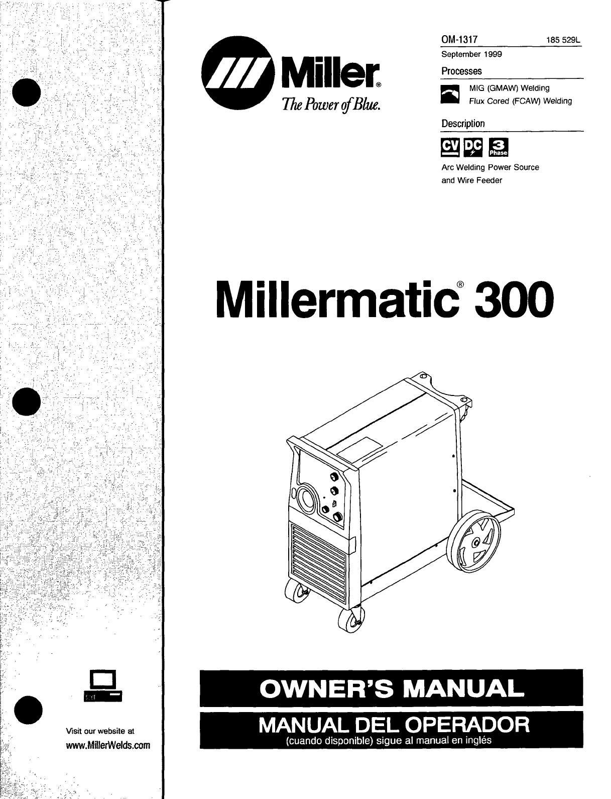
:FIRE:OR
EXPLOSION
hazard.
Do
not
install
or
place
unit
on,
over,
or
near
combustible
surfaces.
Do
not
install
unit
near
flammables.
Do
not
overload
building
wiring
-
be
sure
power
supply
system
is
properly
sized,
rated,
and
protected
to
handle
this
unit.
FALUNG
UNIT
can
cause
injury
Use
lifting
eye
to
lift
unit
only,
NOT
running
gear,
gas
cylinders,
or
any
other
accessories.
Use
equipment
of
adequate
capacity
to
lift
and
support
unit.
If
using
lift
forks
to
move
unit,
be
sure
forks
are
long
enough
to
extend
beyond
opposite
side
of
unit.
OVERUSE
can
causeOVERHEATING
Allow
cooling
period;
follow
rated
duty
cycle.
Reduce
current
or
reduce
duty
cycle
before
starting
to
weld
again.
Do
not
block
or
filter
airflow
to
unit.
STATIC
(ESD~
can
damage
PC.
boards.
Put
on
grounded
wrist
strap
BEFORE
handling
boards
or
parts.
Use
proper
static-proof
bags
and
boxes
to
store,
move,
or
ship
PC
boards.
MOVING
PARTS
can
cause
injury.
Keep
away
from
moving
parts.
Keep
away
from
pinch
points
such
as
drive
rolls.
I
WELDING
WIRE
can
cause
injury
Do
not
press
gun
trigger
until
instructed
to
do
so.
Do
not
point
gun
toward
any
part
of
the
body,
other
people,
or
any
metal
when
threading
welding
wire.
ii
~4.
Principal
Safety
Standards
Safety
in
We/ding
and
Cutting,
ANSI
Standard
Z49.
1,
from
American
Welding
Society,
550
N.W.
LeJeune
Rd,
Miami
FL
33126
Safety
and
Health
Standards,
OSHA
29
CFR
1910,
from
Superinten
dent
of
Documents,
U.S.
Government
Printing
Office,
Washington,
D.C.
20402.
Recommended
Safe
Practices
for
the
Preparation
for
Welding
and
Cutting
of
Containers
That
Have
Held
Hazardous
Substances,
American
Welding
Society
Standard
AWS
F4.1,
from
American
Welding
Society,
550
N.W.
LeJeune
Rd,
Miami,
FL
33126
National
Electrical
Code,
NFPA
Standard
70,
from
National
Fire
Protection
Association,
Batterymarch
Park,
Quincy,
MA
02269.
Keep
all
doors,
panels,
covers,
and
guards
closed
and
securely
in
place.
H.F~
RADIATION
cancause
interference.
High-frequency
(H.F.)
can
interfere
with
radio
navigation,
safety
services,
computers,
and
communications
equipment.
Have
only
qualified
persons
familiar
with
electronic
equipment
perform
this
installation.
The
user
is
responsible
for
having
a
qualified
electrician
promptly
correct
any
interference
problem
resulting
from
the
installation.
If
notified
by
the
FCC
about
interference,
stop
using
the
equipment
at
once.
Have
the
installation
regularly
checked
and
maintained.
Keep
high-frequency
source
doors
and
panels
tightly
shut,
keep
spark
gaps
at
correct
setting,
and
use
grounding
and
shielding
to
minimize
the
possibility
of
interference.
ARC
WELDING
can
cause
interference.
Electromagnetic
energy
can
interfere
with
sensitive
electronic
equipment
such
as
computers
and
computer-driven
equipment
such
as
robots.
Be
sure
all
equipment
in
the
welding
area
is
electromagnetically
compatible.
To
reduce
possible
interference,
keep
weld cables
as
short
as
possible,
close
together,
and
down
low,
such
as
on
the
floor.
Locate
welding
operation
100
meters
from
any
sensitive
elec
tronic
equipment.
Be
sure
this
welding
machine
is
installed
and
grounded
according
to
this
manual.
If
interference
still
occurs,
the
user
must
take
extra
measures
such
as
moving
the
welding
machine,
using
shielded
cables,
using
line
filters,
or
shielding
the
work
area.
Safe
Handling
of
Compressed
Gases
in
Cy/inders,
CGA
Pamphlet
P-i,
from
Compressed
Gas
Association,
1235
Jefferson
Davis
Highway,
Suite
501,
Arlington,
VA
22202.
Code
for
Safety
in
Welding
and
Cutting,
CSA
Standard
W117.2,
from
Canadian
Standards
Association,
Standards
Sales,
178
Rexdale
Boulevard,
Rexdale,
Ontario,
Canada
M9W
1
R3.
Safe
Practices
For
Occupation
And
Educational
Eye
And
Face
Protection,
ANSI
Standard
Z87.1,
from
American
National
Standards
institute,
1430
Broadway,
New
York,
NY
10018.
Cutting
And
Welding
Processes,
NFPA
Standard
51
B,
from
National
Fire
Protection
Association,
Batterymarch
Park,
Quincy,
MA
02269.
1-3.
Additional
Symbols
For
Installation,
Operation,
And
Maintenance
MOVING
PARTS
can
cause
injury
Keep
away
from
moving
parts
such
as
fans.
OM-1317
Page
3

Considerations
About
Welding
And The
Effects
Of
Low
Frequency
Electric
And
Magnetic
Fields
Welding
current,
as
it
flows
through welding
cables,
will
cause
electro
magnetic
fields.
There
has
been
and
still
is
some
concern
about
such
fields.
However,
after
examining
more
than
500
studies
spanning
17
years
of
research,
a
special
blue
ribbon
committee
of
the
National
Research
Council
concluded
that:
The
body
of
evidence,
in
the
committees
judgment,
has
not
demonstrated
that
exposure
to
power-
frequency
electric
and
magnetic
fields
is
a
human-health
hazard.
However,
studies
are
still
going
forth
and
evidence
continues
to
be
examined.
Until
the
final
conclusions
of
the
research
are
reached,
you
may
wish
to
minimize
your
exposure
to
electromagnetic
fields
when
welding
or
cutting.
To
reduce
magnetic
fields
in
the
workplace,
use
the
following
procedures:
1.
Keep
cables
close
together
by
twisting
or
taping
them.
2.
Arrange
cables
to
one
side
and
away
from
the
operator.
3.
Do
not
coil
or
drape
cables
around
your
body.
4.
Keep
welding
power
source
and
cables
as
far
away
from
opera
tor
as
practical.
5.
Connect
work
clamp
to
workpiece
as
close
to
the
weld
as
possible.
About
Pacemakers:
Pacemaker
wearers
consult
your
doctor
first.
If
cleared
by
your
doctor,
then
following
the
above
procedures
is
recommended.
1-5
EMF
Information
OM-1317
Page
4
Safetyin
Welding
and
Cutting,
normeANSi
Z49.1
,
delAmericanWel
ding
Society,
550
N.W.
Lejeune
Rd,
Miami
FL
33126
Safety
and
Health
Sandards,
OSHA
29
CFR
1910,
du
Superintendent
of
Documents,
U.S.
Government
Printing
Office,
Washington,
D.C.
20402.
Recommended
Safe
Practice
for
the
Preparation
for
Welding
and
Cut
ting
of
Containers
That
Have
Held
Hazardous
Substances,
norme
AWS
F4.
1,
de
IAmerican
Welding
Society,
550
NW.
Lejeune
Rd,
Mia
mi
FL 33126
National
Electrical
Code,
NFPA
Standard
70,
de
Ia
National
Fire
Pro
tection
Association,
Batterymarch
Park,
Quincy,
MA
02269.
DonnØes
sur
le
soudage
Ølectrique
et
sur
les
effets,
pour
lorganisme,
des
champs
magnØtiques
basse
frØquence
Le
courant
de
soudage,
pendant
son
passage
dans
les
cŒ,bles
de
sou
dage,
causera
des
champs
ØlectromagnØtiques.
II
y
a eu
et
il
y
a
encore
un
certain
souci
a
propos
de
tels
champs.
Cependant,
aprŁs
avoir
examine
plus
de
500
etudes
qui
ont
ØtØ
faites
pendant
une
pØ
node
de
recherche
de
17
ans,
un
comitØ
special
ruban
bleu
du
National
Research
Council
a
conclu:
Laccumulation
de
preuves,
sui
vant
le
jugement
du
comitØ,
na
pas
dØmontrØ
que
lexposition
aux
champs
magnØtiques
et
champs
Ølectriques
a
haute
frØquence
reprØ
sente
un
risque
a
Ia
sante
humaine.
Toutefois,
des
etudes
sont
toujours
en
cours
et
les
preuves
continuent
a
Œtre
examinØes.
En
at
tendant
que
es
conclusions
finales
de
Ia
recherche
soient
Øtablies,
il
vous
serait
souhaitable
de
rØduire
votre
exposition
aux
champs
Ølec
tromagnØtiques
pendant
le
soudage
ou
le
coupage.
Safe
Handling
of
Compressed
Gases
in
Cylinders,
CGA
Pamphlet
P-i,
de
Ia
Compressed
Gas
Association,
1235
Jefferson
Davis
High
way,
Suite
501,
Arlington,
VA
22202.
RŁgles
de
sØcuritØ
en
soudage,
coupage
ef
procØdØs
connexes,
nor-
me
CSA
Wi
17.2,
de
Association
canadienne
de
normalisation,
vente
de
normes,
178
Rexdale
Boulevard,
Rexdale
(Ontario)
Canada
M9W
1R3.
Safe
Practices
For
Occupation
And
Educational
EyeAnd
Face
Prof
ec
tion,
norme
ANSI
Z87.
1,
de
lAmerican
National
Standards
Institute,
1430
Broadway,
New
York,
NY
10018.
Cutting
and
Welding
Processes,
norme
NFPA
51
B,
de
Ia
National
Fire
Protection
Association,
Batterymarch
Park,
Quincy,
MA
02269.
Afin
de
rØduire
les
champs
Ølectromagnetiques
dans
lenvironnement
de
travail,
respecter
les
consignes
suivantes
1
Garder
les
cables
ensembles
en
es
torsadant
ou
en
les
attachant
avec
du
ruban
adhØsif.
2
Mettre
tous
es
cables
du
ctØ
oppose
de
lopØrateur.
3
Ne
pas
courber
pas
et
ne
pas
entourer
pas
les
cables
autour
de
votre
corps.
4
Garder
le
poste
de
soudage
et
les
cables
le
plus
loin
possible
de
vous.
5
Relier
Ia
pince
de
masse
le
plus
prŁs
possible
de
Ia
zone
de
soudure.
Consignes
relatives
aux
stimulateurs
cardiaques
Les
personnes
qui
portent
un
stimulateur
cardiaque
doivent
avant
tout
consulter
leur
docteur.
Si
vous
Œtes
dØclarØ
apte
par
votre
docteur,
il
est
alors
recommandØ
de
respecter
les
consignes
ci-dessus.
1-4
Principales
normes
de
secuntØ
1-5
Information
sur
les
champs
ØlectromagnØtiques
OM-1317
Pages

SECTION
2-
INSTALLATION
2-1.
Specifications
~1~ax.
Open
Rated
Output
Circuit
Voltage
300
A
at
32
VDC,
I
240
A
at
32
VDC,
38
60%
Duty
Cycle
1100%
Duty
Cycle
Amps
Input
at
Rated
Output,
50
or
60
Hz;
Three-Phase
200
V
230
V
460
V
47
23.5
KVA
KW
18.6
13
54
Wire
Feed
Dimensions
TNet
Weight
Wire
Type
and
Diameter
Speed
Solid
Steel
I
Stainless
Steel
~~iux
Cored
25-700
1PM
H:
37
in
(940
mm)
1275
lb
.023
-
1/16
in
I
.023
-
.035
in
.030
-
1/16
in
(.65-17.8
mfmirl)
W:
19
in
(483
mm)
(125
kg)
D:
30-1/4
in
(768
mm)
(0.6
-
1.6
mm)
(0.6
-
0.9
mm)
(0.8
-
1.6
mm)
*
While
idling
Operating
Temperature
Range
-
-20C
to
+40C
Storage
Temperature
Range
-
-30C
to
+
50C
2-2.
Duty
Cycle
And
Overheating
Overheating
400
250
w
a
z
9
160
Duty
Cycle
is
percentage
of
10
minutes
that
unit
can
weld
at
rated
load
without
overheating.
If
unit
overheats,
thermostat(s)
opens,
output
stops,
and
cooling
fan
runs.
Wait
fifteen
minutes
for
unit
to
cool.
Reduce
amperage
or
voltage,
or
duty
cycle
before
welding.
100
10
15
30 40
5060708090100
%
DUTY
CYCLE
A
Exceeding
duty
cycle
can
damage
unit
and
void
warranty.
6
Minutes
Welding
Cycle
At
240
Amperes
Continuous
Welding
Minutes
~AorV
Reduce
Duty
Cycle
,~
OM-1317
Page
9

2-3.
Volt-Ampere
Curve
S
.
MAX
MIN
1
Normal
Volt-Ampere
Curves
The
volt-ampere
curves
show
the
normal
minimum
and
maximum
50
voltage
and
amperage
output
ca
pabilities
of
the
welding
power
source.
Curves
of
other
settings
fall
between
the
curves
shown.
40
2
Overload
Volt-Ampere
Curves
0)
When
unit
is
used
beyond
capac
H
30
ity,
circuitry
senses
the
overload
and
shuts
down
unit
output.
Re
lease
trigger
and
lower
weld
volt
age
setting
before
trying
to
weld.
o
20
This
shut
down
circuitry
protects
o
internal circuits
and
parts
from
overload
damage.
10
0
0
50
100
150
200
250
300
350 400
DC
AMPERES
ST-185
560
2-4.
Installing
Work
Clamp
OM-1
317
Page
10
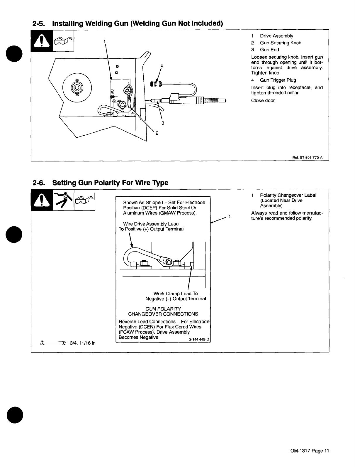
2-5.
Installing
Welding
Gun
(Welding
Gun
Not
Included)
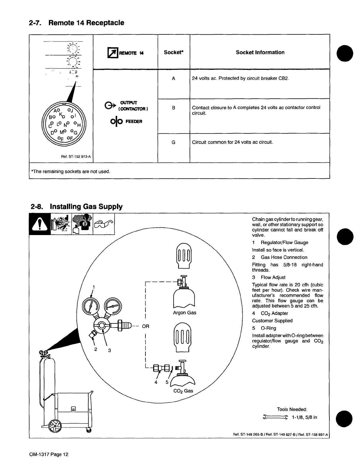
2-6.
Setting
Gun
Polarity
For
Wire
Type
Shown
As
Shipped
-
Set
For
Electrode
Positive
(DCEP)
For
Solid
Steel
Or
Aluminum
Wires
(GMAW
Process).
Wire
Drive
Assembly
Lead
To
Positive
(+)
Output
Terminal
1
Polarity
Changeover
Label
(Located
Near
Drive
Assembly)
Always
read
and
follow
manufac
tures
recommended
polarity.
Work
Clamp
Lead
To
Negative
(-)
Output
Terminal
GUN
POLARITY
CI-IANGEOVER
CONNECTIONS
r
3/4,11/l6in
Reverse
Lead
Connections
-
For
Electrode
Negative
(OCEN)
For
Flux
Cored
Wires
(FCAW
Process).
Drive
Assembly
Becomes
Negative
S14.44490
OM-1317
Page
11
2-7.
Remote
14
Receptacle
B
Contact
closure
to
A
completes
24
volts
ac
contactor
control
circuit.
OR
~
--
i_9
a-
REMOTE
14
Socket*
Socket
Information
A
24
volts
ac.
Protected
by
circuit
breaker
CB2.
,~
OUWuT
~
(CONT~TOR)
010
FEEDER
Ref.
ST-152
973-A
G
*The
remaining
sockets
are
not
used.
Circuit
common
for
24
volts
ac
circuit.
2-8.
Installing
Gas
Supply
Chain
gas
cylinder
to
running
gear,
wall,
or
other
stationary
support
so
cylinder
cannot
fall
and
break
off
valve.
1
Regulator/Flow
Gauge
Install
so
face
is
vertical.
2
Gas
Hose
Connection
Fitting
has
5/8-18
right-hand
threads.
3 Flow
Adjust
Typical
flow
rate
is
20
cfh
(cubic
feet
per
hour).
Check
wire
man
ufacturers
recommended
flow
rate.
This
flow
gauge
can
be
adjusted
between
5
and
25
cfh.
Argon
Gas
4
CO2
Adapter
Customer
Supplied
5
0-Ring
Install
adapter
with
0-ring
between
regulator/flow
gauge
and
CO2
cylinder.
Tools
Needed:
~
1-1/8,5/8in
.
OM-1317
Page
12

2-9.
Installing
Wire
Spool
and
Adjusting
Hub
Tension
OM-1317
Page
13

2-10.
Inductance
Selection
Tools
Needed:
~
3/8,
7/16
in
cI~J===~n
3/8
in
Remove
left
side
panel.
1
Stabilizer
Z
Tapped
stabilizer
Z
is
factory
con
nected
to
the
stabilizer
tap
which
suits
most
GMAW
applications.
Stabilizer
Z
controls
the
induc
tance
applied
to
the
weld
current.
To
increase
inductance
and
wet
out
the
weld
puddle,
connect
to
stabilizer
Z
ending.
To
change
inductance
proceed
as
follows:
2
Lead
24
3
Stabilizer
Z
Tap
4
Stabilizer
Z
Ending
5
Lead
25
To
decrease
inductance,
connect
lead
25
to
stabilizer
tap
and
se
cure.
Reinstall
side
panel.
6
Typical
Weld
Bead
Using
The
Tap
Stabilizer
Connection
Use
the
tap
Stabilizer
connection
when
welding
with
100%
CO2
shielding
gas.
Use
either
stabilizer
connection,
depending
upon
your
arc
prefer
ence,
while
welding
with
a
mixed
shielding
gas.
Use
stabilizer
Z
ending
to
weld
on
stainless
steel.
7
Typical
Weld
Bead
Using
The
End
High
Stabilizer
Connection
Use
the
end
Stabilizer
connection
to
reduce
weld
bead
crowning,
and
spread
the
weld
puddle.
Install
left
side
panel.
Weld
Bead
Using
The
Tap
Stabilizer
Connection
With
17
Volts,
100
Amps
Weld
Bead
Using
The
End
Stabilizer
Connection
With
17
Volts,
100
Amps
2-11.
Electrical
Service
Guide
.
II~
7
Ret.
ST-148
265-B
I
Ret.
ST-801
379-B
input
Voltage
200
230
460
Input
Amperes
At
Rated
Output
54
47
23.5
Max
Recommended
Standard
Fuse
Or
Circuit
Breaker
Rating
In
Amperes
80
70
35
Mm
Input
Conductor
Size
In
AWG/Kcmil
8
8
12
Max
Recommended
Input
Conductor
Length
In
Feet
(Meters)
94
(29)
125
(38)
204
(62)
Mm
Grounding
Conductor
Size
In
AWG/Kcmil
8
8
12
Reference:
1996
National
Electrical
Code
(NEC)
OM-1317
Page
14
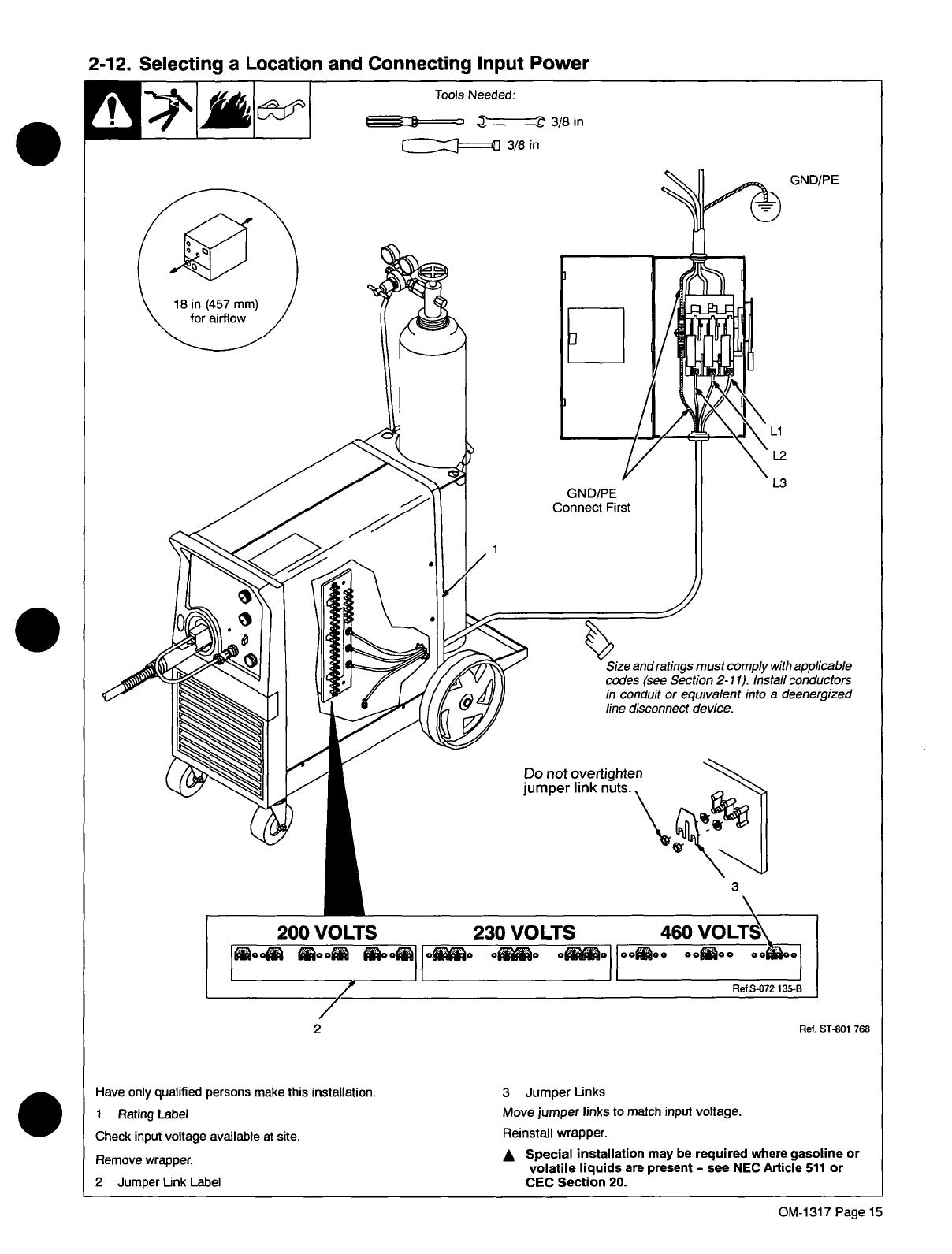
2-12.
Selecting
a
Location
and
Connecting
Input
Power
Tools
Needed:
~~=====zJ
~
3/8
in
c::::::J====IJ
3/8
in
Have
only
qualified
persons
make
this
installation.
I
Rating
Label
Check
input
voltage
available
at
site.
Remove
wrapper.
2
Jumper
Link
Label
3
Jumper
Links
Move
jumper
links
to
match
input
voltage.
Reinstall
wrapper.
A
Special
installation
may
be
required
where
gasoline
or
volatile
liquids
are
present
-
see
NEC
Article
511
or
CEC
Section
20.
GND/PE
Connect
First
Size
and
ratings
must
comply
with
applicable
codes
(see
Section
2-11).
Install
conductors
in
conduit
or
equivalent
into
a
deenergized
line
disconnect
device.
eo~ooI
OM-1317
Page
15

2-13.
Threading
Welding
Wire
1
Wire
Spool
2
Welding
Wire
3
Inlet
Wire
Guide
4
Pressure
Adjustment
Knob
5
Drive
Roll
6
Outlet
Wire
Guide
7
Gun
Conduit
Cable
Lay
gun
cable
out
straight.
Tools
Needed:
Open
pressure
assembly.
Pull
and
hold
wire;
cut
off
end.
Push
wire
thru
guides
into
gun;
continue
to
hold
wire.
Close
and
tighten
pressure
assembly,
and
let
go
of
wire.
*
Remove
gun
nozzle
and
contact
tip.
HJE~
2
Press
gun
trigger
until
wire
comes
out
of
gun.
Reinstall
contact
tip
and
nozzle
1111
II
Feed
wire
to
check
drive
roll
pressure.
Tighten
knob
enough
to
prevent
slipping.
Cut
off
wire.
Close
and
latch
door.
.
OM-1
317
Page
16

SECTION
4-
MAINTENANCE
&TROUBLESHOOTING
4-1.
Routine
Maintenance
before
maintaining,
F,!
~
A
Disconnect
power
during
severe
conditions.
1E~
Maintain
more
often
If
unit
is
used
beyond
capacity
(excessive
wire
feed,
shorted
output,
etc.),
wire
feeds
but
is
not
energized.
Release
gun
trigger
to
reset
this
condition.
Replace
unreadable
labels
Repair
or
replace
cracked
weld
cable
Clean
and
tighten
weld
terminals
/~
Blow
out
or
vacuum
inside.
Remove
drive
roll
and
carrier.
Apply
light
coat
of
oil
or
grease
to
drive
motor
shaft.
4-2.
Circuit
Breakers
CB1
And
CB2
S
1
Circuit
Breaker
CB2
CB2
protects
Remote
14
recep
tacle
RC1
from
overload.
2
Circuit
Breaker
CB1
If
CB1
opens,
wire
feeding
stops.
3
Welding
Gun
(Not
Included)
Check
gun
liner
for
blockage
or
kinks.
4
Wire
Drive
Assembly
Check
for
jammed
wire,
binding
drive
gear
or
misaligned
drive
rolls.
Allow
cooling
period
and
reset
breaker.
Close
door.
Ref.
ST-801
770
4-3.
Unit
Overload
OM-1317
Page
18

Tools
Needed:
1
Securing
Screw
2
Inlet
Wire
Guide
Loosen
screw.
Slide
tip
as
close
to
drive
rolls
as
possible
without
touching.
Tighten
screw.
3
Anti-Wear
Guide
Install
guide
as
shown.
4
Drive
Roll
Install
correct
drive
roll
for
wire
size
and
type.
5
Drive
Roll
Securing
Nut
Turn
nut
one
click
to
secure
drive
roll.
A
Turn
Off
power.
View
is
from
top
of
drive
rolls
look
ing
down
with
pressure
assembly
open.
1
Drive
Roll
Securing
Nut
2
Drive
Roll
3
Wire
Guide
4
Welding
Wire
5
Drive
Gear
Insert
screwdriver,
and
turn
screw
in
or
out
until
drive
roll
groove
lines
up
with
wire
guide.
Close
pressure
roll
assembly.
4-4.
Changing
Drive
Roll
and
Wire
Inlet
Guide
Tools
Needed:
~
7/16
in
5/64
in
Aligning
Drive
Rolls
and
Wire
Guide
ST-i
50
227-C
Correct
Incorrect
5
4
Ref.
ST-800
412-A
OM-1317
Page
19
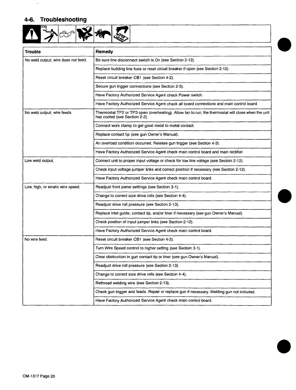
4-6.
Troubleshooting
.
Trouble
Remedy
No
weld
output;
wire
does
not
feed.
Be
sure
line
disconnect
switch
is
On
(see
Section
2-12).
Replace
building
line
fuse
or
reset
circuit
breaker
if
open
(see
Section
2-12).
Reset
circuit
breaker
CB1
(see
Section
4-2).
Secure
gun
trigger
connections
(see
Section
2-5).
Have
Factory
Authorized
Service
Agent
check
Power
switch.
Have
Factory
Authorized
Service
Agent
check
all
board
connections
and
main
control
board.
No
weld
output;
wire
feeds.
Thermostat
TP2
or
TP3
open
(overheating).
Allow
fan
to
run;
the
thermostat
will
close
when
the
unit
has
cooled
(see
Section
2-2).
Connect
work
clamp
to
get
good
metal
to
metal
contact.
Replace
contact
tip
(see
gun
Owners
Manual).
An
overload
condition
occurred.
Release
gun
trigger
(see
Section
4-3).
Have
Factory
Authorized
Service
Agent
check
main
control
board
and
main
rectifier.
Low
weld
output.
Connect
unit
to
proper
input
voltage
or
check
for
low
line
voltage
(see
Section
2-12).
Check
input
voltage
jumper
links
and
correct
position
if
necessary
(see
Section
2-12).
Have
Factory
Authorized
Service
Agent
check
main
control
board.
Low,
high,
or
erratic
wire
speed.
Readjust
front
panel
settings
(see
Section
3-1).
Change
to
correct
size
drive
rolls
(see
Section
4-4).
Readjust
drive
roll
pressure
(see
Section
2-13).
Replace
inlet
guide,
contact
tip,
and/or
liner
if
necessary
(see
gun
Owners
Manual).
Check
position
of
input
jumper
links
(See
Section
2-12).
Have
Factory
Authorized
Service
Agem
check
main
control
board.
No
wire
feed.
Reset
circuit
breaker
CB1
(see
Section
4-2).
Turn
Wire
Speed
control
to
higher
setting
(see
Section
3-1).
Clear
obstruction
in
gun
contact
tip
or
liner
(see
gun
Owners
Manual).
Readjust
drive
roll
pressure
(see
Section
2-13).
Change
to
correct
size
drive
rolls
(see
Section
4-4).
Rethread
welding
wire
(see
Section
2.13).
Check
gun
trigger
and
leads.
Repair
or
replace
gun
if
necessary.
Welding
gun
not
included.
Have
Factory
Authorized
Service
Agent
check
main
control
board.
OM-1317
Page
20
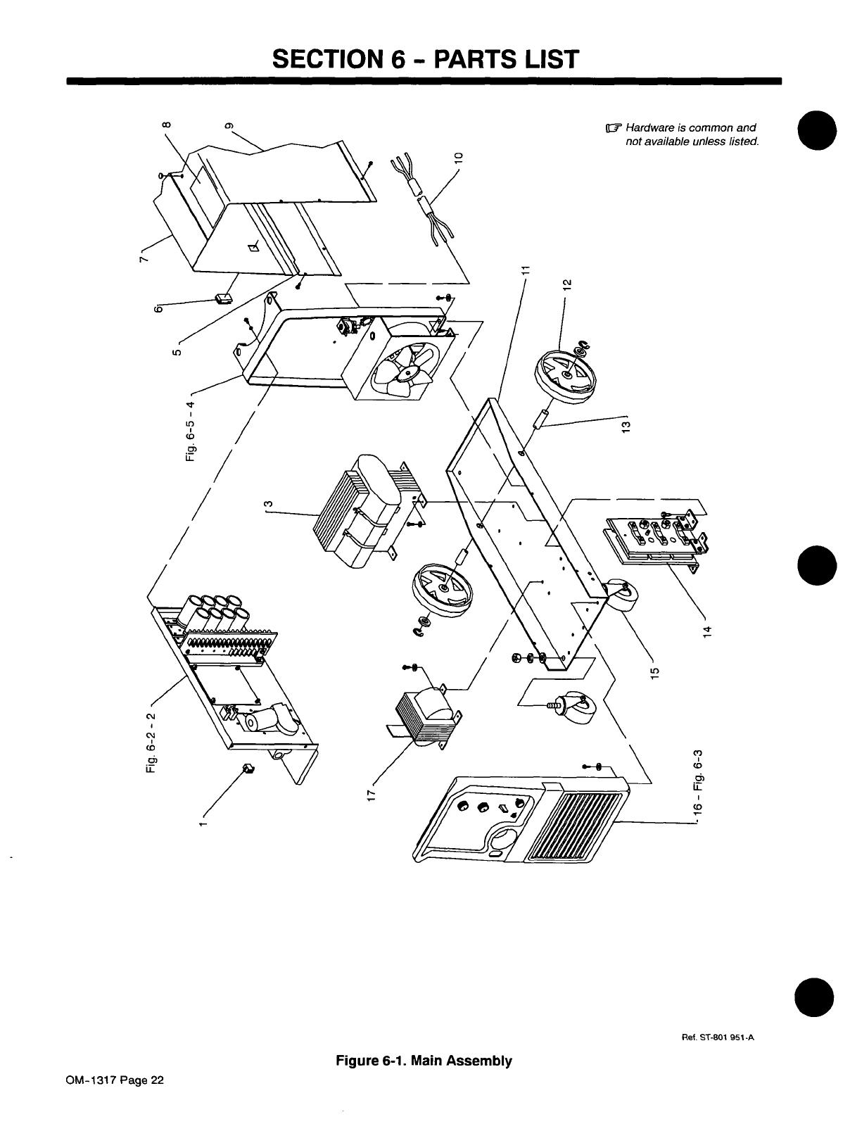
SECTION
6-
PARTS
LIST
Ref.
ST-8O1
951-A
.
Figure
6-1.
Main
Assembly
0)
0
1~-
Hardware
is
common
and
not
available
unless
listed.
to
04
LU
C)
IL
/
/
/
0)
/
04
(4
CD
U-
to
/
Co
U-
Co
OM-1317
Page
22
/