
INSTRUCTIONS
57004D 12/13 (JRK)
English
The thermostat is an electronic on/off
thermostat for temperature control by means
of an NTC sensor located either externally or
internally within the thermostat. The thermostat
has a built-in ground fault circuit interrupter
(GFCI, Class A). The thermostat and GFCI are
dual models suitable for 120-240 V (incl. 208 V)
50/60 Hz power supplies.
The thermostat is for flush mounts in a wall
socket.
Product programme
Thermostats with built-in GFCI
UCG-4991 Programmable thermostat incl.
floor sensor
UDG-4999 Programmable thermostat with
2 sensors:
floor sensor and built-in room
sensor
UTN-4991 Non-programmable thermostat
incl. floor sensor
Power module with built-in GFCI
USG-4000 Power module without sensor
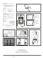
Mounting of floor sensor (fig. 3)
Floor sensor is supplied from SELV (Safety
Extra low Voltage) Circuit, allowing the sensor
to be placed as close to the floor surface as
desired without having to take special account
to the risk of shock at the damage to the sensor
cable. It is not intended that the temperature
sensor wire shall enter through the wall socket
mounting box. The sensor cable shall be
seperated from LINE and LOAD cables. Can
be separated in conduite, inside or outside the
wall. (see fig. 7)
Recommended placed in an non conductive
installation pipe, which is embedded in the
floor. (fig. 3). The pipe must be sealed in the end
and placed as high as possible in the concrete
layer. Alternativerly, the floor sensor is monted
directly in the floor construction. The sensor
cable shall be placed in a separate pipe or be
separated from power cables.
The floor sensor must be centered in between
the heating cable.
Sensor cable can be extended up to 300 ft (100
m.) by means of a separate two-core cable.
Two remaining cores of a multi-core cable
which, for example, supplies current to the floor
heating wires, must not be used. The two-core
cable must be placed in a separate pipe or be
separated from power cables.
Other approved floor sensors can be used if
they comply with the technical specifications
(see fig. 5).
Mounting of thermostat with built-in sensor
(UDG-4999) (fig. 4)
The room sensor is used for comfort
temperature regulation in rooms. The
thermostat should be mounted on the wall
approx. 5.4 ft (1.6 m) above the floor in such
a way as to allow free air circulation around
it. Draughts and direct sunlight or other heat
sources must be avoided.
Mounting of thermostat
Installation
TO AVOID ELECTRIC SHOCK,
DISCONNECT THE HEATING
SYSTEM POWER SUPPLY AT THE
MAIN PANEL BEFORE INSTALLING
THE THERMOSTAT.
KEEP THERMOSTAT AIR VENTS CLEAN AND
FREE FROM OBSTRUCTION.
This thermostat is an electrical product
and must be installed in compliance with
the National and/or Local Electrical Code.
Installation must be performed by qualified
personnel where required by law. The
thermostat is equipped with a ground fault
circuit interrupter (GFCI, Class A) which requires
that the line and load cables are isolated from
one another for correct operation. The thermostat
is designed for resistive load. The resistive load
must not exceed 15 A (1800 W at 120 Vac / 3120
W at 208 Vac / 3600 W at 240 Vac).
During a ground fault, the two lines will be cut
off.
Line cable
Delivers power from the service panel (breaker
panel or fuse box) to the thermostat.
This cable must only be connected to the
thermostat’s line terminals, marked L1 and L2.
1. Connect power cable to terminals 2 and 3
on the back of the thermostat (fig. 2).
Load cable
Delivers power from the thermostat to the
heating cable.
This cable must only be connected to the
thermostat’s load terminals, marked load 15 A.
1. Connect heating cable to terminals 1 and 4
on the back of the thermostat (fig. 2).
Warning
Do not loosen the terminal screws
further than the mechanical stop.
Otherwise this will damage the
terminal (fig. 2).
Temperature sensor
1. Use a screwdriver to release the catch and
remove the front cover (fig. 1).
2. Connect the floor sensor to the terminals
marked “sensor”, terminals C and D (fig. 6).
3. Mount the thermostat in the wall socket.
4. Carefully replace the front cover by first
positioning its upper edge and then clicking it
into place.
Power module, type USG
If loads of more than 15 A are required,
expansion is possible using power modules.
Power modules can be connected to the live
cable and load cable, see relevant sections.
Maximum distance between thermostat and
power modules is 80 ft (25 m.)
Use field wiring cable, recommended min. 20
AWG. Connect A to C and B to D (fig. 6).
Operation
Types UCG and UDG (with built-in clock):
The first time the thermostat is connected,
time and day must be set. The thermostat will
automatically start up in the menu for setting
time and day.
Type UTN (without built-in clock):
The actual temperature setting is shown and the
thermostat is ready for use.
Checking the GFCI
It is important that the GFCI is checked for
correct installation and function.
To check the GFCI:
Testing can only be performed while the
thermostat is calling for heat.
Adjust the setpoint until the heating symbol (
)
appears. Use the “Up” button to increase
the heating demand and then press the “OK”
button. Wait 10 seconds to allow the thermostat
to adjust to the new setpoint.
Then press the “TEST” button.
The test is successful if the red light in the
“TEST” button lights up and “GROUND FAULT”
is shown on the display. If this does not occur,
check the installation.
Press the “Standby/Reset” button to reset the
GFCI.
The red light should go out and the display
returns to normal appearance.
Press the “Down” button to return to the original
temperature setting.
If the test fails, check the heating cable and
thermostat.
The GFCI should be tested monthly.
If during normal operation the GFCI trips
without the “TEST” button being pressed, there
could be a ground fault! To check whether it
is a ground fault or nuisance tripping, press
“Standby/Reset”. If this causes the red light to
go off and stay off, it was nuisance tripping and
the system is operating correctly. If this does
not occur, there is a ground fault!
Check the heating cable, sensor cable and
thermostat. Replace the defective part.
Programming
See user manual.
Fault location
If the sensor is disconnected or short-circuited,
the heating system is switched off. The sensor
can be checked against the resistance table
(fig. 5).
Error codes
E0: Internal error. The thermostat must be
replaced.
E1: Built-in sensor short-circuited or
disconnected. The thermostat must be
replaced (n/a for UTN-4991)
E2: External sensor short-circuited or
disconnected.
UL Listed for the US and Canada
According to the following standards:
Thermostat: UL 873
CSA C22.2 No. 24.
UL file number: E157297
GFCI: UL 943 4th ed.
CSA C22.2 No. 144.1-06
Classification
The product is a class II device (enhanced
insulation) and must be connected to the
following leads:
Phase L1 (L) 120-240 V ±10%, 50/60 Hz
Neutral L2 (N)
Max. load 15 A (resistive load)
The terminals are suitable for field wiring cables
of 12 to 22 AWG.
Type UDG, UCG, UTN, USG
© 2013 OJ Electronics A/S
Page is loading ...
Page is loading ...

Fig. 1 BR0964A08a
Fig. 2 BR0964A06a
OJ ELECTRONICS A/S
Stenager 13B · DK-6400 Sønderborg
Tel. +45 73 12 13 14 · Fax +45 73 12 13 13
[email protected] · www.ojelectronics.com
The trademark is registered and belongs to OJ Electronics A/S · © 2013 OJ Electronics A/S
BR928A07a
Sensor
Temp.(˚C)
Value (ohm)
-10
0
10
20
30
64000
38000
23300
14800
9700
Temp.(˚F)
68
86
50
32
-14
Fig. 5 BR928A07a
BR928A04
1,6m
Fig.4 BR928A04a
Fig. 3
BR-0964-A01d
© 2011 OJ Electronics A/S
Fig. 6 BR0964A01d
1
22
1
BR0964A02b
Fig. 7 BR0964A02b
Códigos de error
E0: Error interno. Es necesario cambiar el ter-
mostato.
E1: Sensor integrado en cortocircuito o desco-
nectado. Es necesario cambiar el termosta-
to (no se aplica al UTN-4991)
E2: Sensor externo en cortocircuito o desco-
nectado.
c-UL-us
De acuerdo con las normativas siguientes:
Termostato: UL 873
CSA C22.2 No. 24.
Núm. de archivo UL: E157297
GFCI: UL 943 4th ed.
CSA C22.2 No. 144.1-06
Clasificación
El producto es un dispositivo clase II (con ais-
lamiento mejorado) y deberá conectarse a los
conductores siguientes:
Fase L1 (L) 120-240 V ±10%, 50/60 Hz
Neutro L2 (N)
Carga máxima: 15 A (carga resistiva)
Los terminales son compatibles con alambres
de cableado de campo con calibres 12 al 22
AWG.
Datos técnicos
Alimentación ...............120-240 V CA 50/60 Hz
Carga máxima: .................. 15 A (carga resistiva)
Potencia ..................... 1800 W a 120 V CA
..................... 3120 W a 208 V CA
..................... 3600 W a 240 V CA
GFCI .............Clase A (nivel de disparo
de 5 mA)
Rango de temperatura .......................................
+5 a +40 °C, +41 a +104 °F
Rango de temperatura ambiente ........................
.....................................................
0 a +25 °C, +32 a +77°F
1
234
LOAD
1800W/3600W MAX 15A
LINE
120 / 240 VAC
L1(L)
L2(N)
WARNING
When fastening the screws
do NOT exceed a torque
greater than
1.2 Nm
WARNING
When loosening the screws
do NOT detach the screws
from the terminal.
ES: Advertencia
Al apretar los tornillos no
aplique un par de apriete
mayor que 1,2 N-m.
FR: Avertissement
Lors du serrage des
vis, ne pas excéder un
couple de 1,2 Nm.
ES: Advertencia
Al aflojar los tornillos, no
los separe completamente
del terminal.
FR: Avertissement
En desserrant les vis,
ne pas les enlever
des bornes.
-
 1
1
-
 2
2
-
 3
3
-
 4
4


WarmlyYours UDG-4999 Installation guide
- Category
- Thermostats
- Type
- Installation guide
Ask a question and I''ll find the answer in the document
Finding information in a document is now easier with AI
in other languages
Related papers
-
WarmlyYours UDG-4999 User manual
-
WarmlyYours UCDG User manual
-
-
WarmlyYours UTN4-4999 Quick start guide
-
WarmlyYours UDG Installation guide
-
-
-
 Aube Technologies TH114 A/F/AF Thermostat User manual
-
-

Other documents
-
-
Danfoss 088L5133 User guide
-
OJ Electronics UTN User manual
-
-
Schluter DHERR1/BW User manual
-
-
Warmup UCCG-4991 Floor Heating Thermostat Installation guide
-
-
-