
ADD MANUAL TITLE
Wolf Steel Ltd., 24 Napoleon Rd., Barrie, ON, L4M 0G8 Canada / 103 Miller Drive, Crittenden, Kentucky, USA, 41030
Phone 1 (866) 820-8686 • www.napoleonfi replaces.com • hearth@napoleonproducts.com
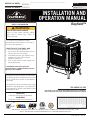
CERTIFIED TO THE CANADIAN AND AMERICAN NATIONAL STANDARDS:
CSA 2.22 AND ANSI Z21.50 FOR VENTED DECORATIVE GAS APPLIANCES
INSTALLER:
Leave this manual with the appliance
CONSUMER:
Retain this manual for future reference
ADD PRODUCT CODE HERE (TRADE GOTHIC LT STD FONT)
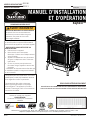
NATURAL GAS MODELS:
PROPANE GAS MODELS:
PRODUCT NAME™
ADD ____ ILLUSTRATED
ADD PRODUCT IMAGE
CSA /
INTERTEK
LOGO
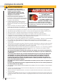
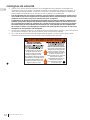
SAFETY INFORMATION
- Do not store or use gasoline or other
fl ammable vapors and liquids in the vicinity of
this or any other appliance.
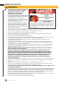
- WHAT TO DO IF YOU SMELL GAS:
• Do not try to light any appliance.
• Do not touch any electrical switch; do not
use any phone in your building.
• Immediately call your gas supplier from a
neighbour’s phone. Follow the gas
supplier’s instructions.
• If you cannot reach your gas supplier, call
the fi re department.
- Installation and service must be
performed by a qualifi ed installer, service
agency, or the supplier.
This appliance may be installed in an aftermarket,
permanently located, manufactured home (USA
only) or mobile home, where not prohibited by
local codes.
This appliance is only for use with the type of gas
indicated on the rating plate. This appliance is
not convertible for use with other gases, unless
a certifi ed kit is used.
FIRE OR EXPLOSION HAZARD
Failure to follow safety warnings exactly
could result in serious injury, death, or
property damage.
WARNING
!
ENGLISH
$10.00
FOR INDOOR USE ONLY
SAFETY BARRIER
GDS25N-1
GDS25P-1
Bayfield™
INSTALLATION AND
OPERATION MANUAL
FRENCH
PG. 51
W415-2207 / B / 02.05.18

• This appliance is hot when operated and
can cause severe burns if contacted.
• Any changes or alterations to this
appliance or its controls can be
dangerous and is prohibited.
• Do not operate appliance before reading and
understanding operating instructions. Failure
to operate appliance according to operating
instructions could cause fi re or injury.
• Ensure the glass door is opened or removed
when lighting the pilot for the fi rst time and
when the gas supply has run out.
• Risk of fi re or asphyxiation do not operate
appliance with fi xed glass removed and never
obstruct the front opening of the appliance.
• Objects placed in front of the appliance must
be kept a minimum of 4 feet (1.22m) from the
front face of the appliance.
• Do not connect 110 volts to the control valve,
with the exception of models; GSST8 and GT8.
• Risk of burns. The appliance should be turned off and cooled before servicing.
• Do not install damaged, incomplete or substitute components.
• Risk of cuts and abrasions. Wear protective gloves, protective footwear, and safety glasses during
installation. Sheet metal edges may be sharp.
• Do not burn wood or other materials in this appliance.
• Provide adequate ventilation and combustion air. Provide adequate accessibility clearance for servicing
and operating the appliance. Never obstruct the front opening of the appliance.
• The appliance area must be kept clear and free from combustible materials, gasoline and other
fl ammable vapors and liquids.
• High pressure will damage valve. Disconnect gas supply piping before pressure testing gas line at
test pressures above 1/2 psig. Close the manual shut-off valve before pressure testing gas line at test
pressures equal to or less than 1/2 psig (35mb).
• The appliance must not be operated at temperatures below freezing (32°F / 0°C). Allow the appliance
to warm to above freezing prior to operation, with the exception of models; GSS36, GSS42; these
appliances are suitable for 0°F / -18°C.
• Children and adults should be alerted to hazards of high surface temperature and should stay
away to avoid burns or clothing ignition.
• Young children should be carefully supervised when they are in the same room as the
appliance. Toddlers, young children and others may be susceptible to accidental contact
burns. A physical barrier is recommended if there are at risk individuals in the house. To
restrict access to an appliance or stove, install an adjustable safety gate to keep toddlers,
young children and other at risk individuals out of the room and away from hot surfaces.
• Clothing or other fl ammable material should not be placed on or near the appliance.
• Due to high temperatures, the appliance should be located out of traffi c and away from
furniture and draperies.
• Furniture or other objects must be kept a minimum of 4 feet (1.22m) away from the front of the appliance.
• Ensure you have incorporated adequate safety measure to protect infants/toddlers from touching hot
surfaces.
• Even after the appliance is off, it will remain hot for an extended period of time.
• Check with your local hearth specialty dealer for safety screens and hearth guards to protect children
from hot surfaces. These screens and guards must be fastened to the fl oor.
• Any safety screen, guard or barrier removed for servicing the appliance, must be replaced prior
to operating the appliance.
• It is imperative that the control compartments, burners and circulating blower and its passageway in the
appliance and venting system are kept clean. The appliance and its venting system should be inspected
before use and at least annually by a qualifi ed service person. More frequent cleaning may be required
due to excessive lint from carpeting, bedding material, etc. The appliance area must be kept clear and
free from combustible materials, gasoline and other fl ammable vapors and liquids.
• If the appliance shuts off, do not re-light until you provide fresh air. If appliance keeps shutting off, have it
serviced. Keep burner and control compartment clean.
• Under no circumstances should this appliance be modifi ed.
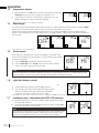
LA VITRE CHAUDE CAUSERA
DES BRÛLURES.
NE PAS TOUCHER LA VITRE
AVANT QU’ELLE AIT REFROIDI.
NE JAMAIS LAISSER LES
ENFANTS TOUCHER LA VITRE.
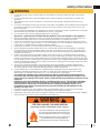
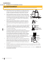
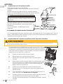
HOT GLASS WILL CAUSE
BURNS.
DO NOT TOUCH GLASS UNTIL
COOLED.
NEVER ALLOW CHILDREN TO
TOUCH GLASS.
!
DANGER
!
AVERTISSEMENT
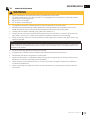
A barrier designed to reduce the risk of burns from the
hot viewing glass is provided with this appliance and
shall be installed for the protection of children and other
at-risk individuals.
Une barriére conçu à réduire le risque de brûlures
causées par le verre chaud est fourni avec l’appareil et
sera installé pour la protection des enfants et d’autres
personnes à risque.
3.1B
!
WARNING
!
WARNING
• Do not allow wind or fans to blow directly into the appliance. Avoid any drafts that alter burner fl ame
patterns.
• Do not use a blower insert, heat exchanger insert or other accessory not approved for use with this
appliance.
• This appliance must not be connected to a chimney fl ue pipe serving a separate solid fuel burning
appliance.
• Do not use this appliance if any part has been under water. Immediately call a qualifi ed service technician
to inspect the appliance and to replace any part of the control system and any gas control which has
been under water.
• Do not operate the appliance with the glass door removed, cracked or broken. Replacement of the glass
should be done by a licensed or qualifi ed service person, if equipped.
• Do not strike or slam shut the appliance glass door, if equipped.
• Only doors / optional fronts certifi ed with the appliance are to be installed on the appliance.
• Keep the packaging material out of reach of children and dispose of the material in a safe manner. As
with all plastic bags, these are not toys and should be kept away from children and infants.
• Carbon or soot should not occur in a vent free appliance as it can distribute into the living area of your
home. If you notice any signs of carbon or soot, immediately turn off your appliance and arrange to have
it serviced by a qualifi ed technician before operating it again.
• If equipped, the screen must be in place (closed) when the appliance is in operation.
• When equipped with pressure relief doors, they must be kept closed while the appliance is operating
to prevent exhaust fumes containing carbon monoxide, from entering into the home. Temperatures of
the exhaust escaping through these openings can also cause the surrounding combustible materials to
overheat and catch fi re.
• Carbon monoxide poisoning may lead to death; early signs of carbon monoxide poisoning resemble
the fl u, with headache, dizziness and/or nausea. If you have these signs, the heater may not be working
properly. Get fresh air at once! Have heater serviced. Some people; pregnant women, persons with heart
or lung disease, anemia, those under the infl uence of alcohol, those at high altitudes are more affected by
carbon monoxide than others. Failure to keep the primary air opening(s) of the burner(s) clean may result
in sooting and property damage.
• As with any combustion appliance, we recommend having your appliance regularly inspected and
serviced as well as having a Carbon Monoxide Detector installed in the same area to defend you and
your family against Carbon Monoxide.(Not applicable for outdoor appliances).
• Ensure clearances to combustibles are maintained when building a mantel or shelves above the
appliance. Elevated temperatures on the wall or in the air above the appliance can cause melting,
discolouration or damage to decorations, a T.V. or other electronic components.
• For appliances equipped with a safety barrier; the barrier is designed to reduce the risk of
burns from the hot viewing glass is provided with this appliance and shall be installed. If the
barrier becomes damaged, the barrier shall be replaced with the manufacturer’s barrier for this
appliance.
• Installation and repair should be done by a qualifi ed service person. The appliance should be
inspected before use and at least annually by a professional service person. More frequent
cleaning may be required due to excessive lint from carpeting, bedding material, etc. It
is imperative that control compartments, burners and circulating air passageways of the
appliance be kept clean.
• For outdoor products only: this appliance must not be installed indoors or within any structure that
prevents or inhibits the exhaust gases from dissipating in the outside atmosphere.
• If applicable, the millivolt version of this appliance uses and requires a fast acting thermocouple. Replace
only with a fast acting thermocouple supplied by Wolf Steel Ltd.
!
WARNING
!
Disconnect the appliance main gas valve/control
from the supply piping when pressure testing that
system at pressures in excess of 1/2 psi (3.5 kPa).
Isolate the appliance with it’s shut off valve during
any pressure testing of the supply piping at
pressures equal to or less than 1/2 psi (3.5 kPa).
FIRE RISK HAZARD / DELAYED IGNITION
High supply pressure will damage the valve / controls.
EN
W415-2207 / B / 02.05.18
2
safety information

safety information
EN
W415-2207 / B / 02.05.18
3
• This appliance is hot when operated and
can cause severe burns if contacted.
• Any changes or alterations to this
appliance or its controls can be
dangerous and is prohibited.
• Do not operate appliance before reading and
understanding operating instructions. Failure
to operate appliance according to operating
instructions could cause fi re or injury.
• Ensure the glass door is opened or removed
when lighting the pilot for the fi rst time and
when the gas supply has run out.
• Risk of fi re or asphyxiation do not operate
appliance with fi xed glass removed and never
obstruct the front opening of the appliance.
• Objects placed in front of the appliance must
be kept a minimum of 4 feet (1.22m) from the
front face of the appliance.
• Do not connect 110 volts to the control valve,
with the exception of models; GSST8 and GT8.
• Risk of burns. The appliance should be turned off and cooled before servicing.
• Do not install damaged, incomplete or substitute components.
• Risk of cuts and abrasions. Wear protective gloves, protective footwear, and safety glasses during
installation. Sheet metal edges may be sharp.
• Do not burn wood or other materials in this appliance.
• Provide adequate ventilation and combustion air. Provide adequate accessibility clearance for servicing
and operating the appliance. Never obstruct the front opening of the appliance.
• The appliance area must be kept clear and free from combustible materials, gasoline and other
fl ammable vapors and liquids.
• High pressure will damage valve. Disconnect gas supply piping before pressure testing gas line at
test pressures above 1/2 psig. Close the manual shut-off valve before pressure testing gas line at test
pressures equal to or less than 1/2 psig (35mb).
• The appliance must not be operated at temperatures below freezing (32°F / 0°C). Allow the appliance
to warm to above freezing prior to operation, with the exception of models; GSS36, GSS42; these
appliances are suitable for 0°F / -18°C.
• Children and adults should be alerted to hazards of high surface temperature and should stay
away to avoid burns or clothing ignition.
• Young children should be carefully supervised when they are in the same room as the
appliance. Toddlers, young children and others may be susceptible to accidental contact
burns. A physical barrier is recommended if there are at risk individuals in the house. To
restrict access to an appliance or stove, install an adjustable safety gate to keep toddlers,
young children and other at risk individuals out of the room and away from hot surfaces.
• Clothing or other fl ammable material should not be placed on or near the appliance.
• Due to high temperatures, the appliance should be located out of traffi c and away from
furniture and draperies.
• Furniture or other objects must be kept a minimum of 4 feet (1.22m) away from the front of the appliance.
• Ensure you have incorporated adequate safety measure to protect infants/toddlers from touching hot
surfaces.
• Even after the appliance is off, it will remain hot for an extended period of time.
• Check with your local hearth specialty dealer for safety screens and hearth guards to protect children
from hot surfaces. These screens and guards must be fastened to the fl oor.
• Any safety screen, guard or barrier removed for servicing the appliance, must be replaced prior
to operating the appliance.
• It is imperative that the control compartments, burners and circulating blower and its passageway in the
appliance and venting system are kept clean. The appliance and its venting system should be inspected
before use and at least annually by a qualifi ed service person. More frequent cleaning may be required
due to excessive lint from carpeting, bedding material, etc. The appliance area must be kept clear and
free from combustible materials, gasoline and other fl ammable vapors and liquids.
• If the appliance shuts off, do not re-light until you provide fresh air. If appliance keeps shutting off, have it
serviced. Keep burner and control compartment clean.
• Under no circumstances should this appliance be modifi ed.
LA VITRE CHAUDE CAUSERA
DES BRÛLURES.
NE PAS TOUCHER LA VITRE
AVANT QU’ELLE AIT REFROIDI.
NE JAMAIS LAISSER LES
ENFANTS TOUCHER LA VITRE.
HOT GLASS WILL CAUSE
BURNS.
DO NOT TOUCH GLASS UNTIL
COOLED.
NEVER ALLOW CHILDREN TO
TOUCH GLASS.
!
DANGER
!
AVERTISSEMENT
A barrier designed to reduce the risk of burns from the
hot viewing glass is provided with this appliance and
shall be installed for the protection of children and other
at-risk individuals.
Une barriére conçu à réduire le risque de brûlures
causées par le verre chaud est fourni avec l’appareil et
sera installé pour la protection des enfants et d’autres
personnes à risque.
3.1B
!
WARNING
!
WARNING
• Do not allow wind or fans to blow directly into the appliance. Avoid any drafts that alter burner fl ame
patterns.
• Do not use a blower insert, heat exchanger insert or other accessory not approved for use with this
appliance.
• This appliance must not be connected to a chimney fl ue pipe serving a separate solid fuel burning
appliance.
• Do not use this appliance if any part has been under water. Immediately call a qualifi ed service technician
to inspect the appliance and to replace any part of the control system and any gas control which has
been under water.
• Do not operate the appliance with the glass door removed, cracked or broken. Replacement of the glass
should be done by a licensed or qualifi ed service person, if equipped.
• Do not strike or slam shut the appliance glass door, if equipped.
• Only doors / optional fronts certifi ed with the appliance are to be installed on the appliance.
• Keep the packaging material out of reach of children and dispose of the material in a safe manner. As
with all plastic bags, these are not toys and should be kept away from children and infants.
• Carbon or soot should not occur in a vent free appliance as it can distribute into the living area of your
home. If you notice any signs of carbon or soot, immediately turn off your appliance and arrange to have
it serviced by a qualifi ed technician before operating it again.
• If equipped, the screen must be in place (closed) when the appliance is in operation.
• When equipped with pressure relief doors, they must be kept closed while the appliance is operating
to prevent exhaust fumes containing carbon monoxide, from entering into the home. Temperatures of
the exhaust escaping through these openings can also cause the surrounding combustible materials to
overheat and catch fi re.
• Carbon monoxide poisoning may lead to death; early signs of carbon monoxide poisoning resemble
the fl u, with headache, dizziness and/or nausea. If you have these signs, the heater may not be working
properly. Get fresh air at once! Have heater serviced. Some people; pregnant women, persons with heart
or lung disease, anemia, those under the infl uence of alcohol, those at high altitudes are more affected by
carbon monoxide than others. Failure to keep the primary air opening(s) of the burner(s) clean may result
in sooting and property damage.
• As with any combustion appliance, we recommend having your appliance regularly inspected and
serviced as well as having a Carbon Monoxide Detector installed in the same area to defend you and
your family against Carbon Monoxide.(Not applicable for outdoor appliances).
• Ensure clearances to combustibles are maintained when building a mantel or shelves above the
appliance. Elevated temperatures on the wall or in the air above the appliance can cause melting,
discolouration or damage to decorations, a T.V. or other electronic components.
• For appliances equipped with a safety barrier; the barrier is designed to reduce the risk of
burns from the hot viewing glass is provided with this appliance and shall be installed. If the
barrier becomes damaged, the barrier shall be replaced with the manufacturer’s barrier for this
appliance.
• Installation and repair should be done by a qualifi ed service person. The appliance should be
inspected before use and at least annually by a professional service person. More frequent
cleaning may be required due to excessive lint from carpeting, bedding material, etc. It
is imperative that control compartments, burners and circulating air passageways of the
appliance be kept clean.
• For outdoor products only: this appliance must not be installed indoors or within any structure that
prevents or inhibits the exhaust gases from dissipating in the outside atmosphere.
• If applicable, the millivolt version of this appliance uses and requires a fast acting thermocouple. Replace
only with a fast acting thermocouple supplied by Wolf Steel Ltd.
!
WARNING
!
Disconnect the appliance main gas valve/control
from the supply piping when pressure testing that
system at pressures in excess of 1/2 psi (3.5 kPa).
Isolate the appliance with it’s shut off valve during
any pressure testing of the supply piping at
pressures equal to or less than 1/2 psi (3.5 kPa).
FIRE RISK HAZARD / DELAYED IGNITION
High supply pressure will damage the valve / controls.

1.0 general information 5
1.1 rates and efficiencies 5
1.2 installation overview 6
1.3 rating plate information 8
1.4 mobile home installation 8
1.5 hardware list 9
1.6 dimensions 10
2.0 venting requirements 11
2.1 typical venting installation 13
2.2 special vent installations 14
2.2.1 periscope termination 14
2.2.2 corner termination 14
2.3 vent terminal clearances 15
2.4 horizontal termination 16
2.5 vertical termination 17
2.6 vertical through existing chimney 18
3.0 installation 19
3.1 horizontal installation 20
3.2 vertical installation 20
3.3 horizontal air terminal installation 21
3.4 extended horizontal and corner air terminal
installation 21
3.5 vertical air terminal Installation 22
3.6 appliance vent connection 23
3.7 gas installation 23
3.8 minimum clearance to combustibles 24
3.9 minimum mantel or shelf clearances 25
4.0 finishing 26
4.1 cast front installation and removal 26
4.2 safety barrier installation and removal 26
4.3 glass door installation and removal 27
4.4 log placement 27
4.5 logo placement 28
5.0 optional blower installation 29
6.0 wiring diagram 31
7.0 operation 32
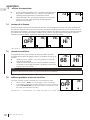
7.1 general transmitter layout 33
7.2 initializing the transmitter / battery holder
for the first time 33
7.3 temperature display 34
7.4 flame height 34
7.5 blower speed 34
7.6 night light dimmer control 34
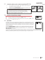
7.7 continuous pilot / intermittent pilot
(CPI / IPI) selection 34
7.8 key lock 35
7.9 low battery / manual bypass 35
8.0 adjustment 36
8.1 restricting vertical vents 36
8.2 venturi adjustment 36
8.3 pilot burner adjustment 36
8.4 flame characteristics 37
9.0 maintenance 38
9.1 annual maintenance 39
9.2 night light replacement 40
9.3 pilot injector and orifice replacement 40
9.4 care of glass 41
9.5 care of plated parts 41
10.0 replacements 42
10.1 overview 43
10.2 valve train assembly 44
11.0 accessories 45
12.0 troubleshooting 46
13.0 warranty 49
The information throughout this manual is believed to be correct at the time of printing. Wolf Steel
Ltd. reserves the right to change or modify any information within this manual at any time without
notice. Changes, other than editorial, are denoted by a vertical line in the margin.
note:
The camera icon indicates video tutorials are available as additional reference, visit
http://www.napoleonfireplaces.com/category/product-support/support-centre/
EN
W415-2207 / B / 02.05.18
4
table of contents

Installer, please fill out the following information:
Customer:
Address:
Date of Installation:
Location of appliance:
Installer:
Dealer/Distributor contact number:
Serial #:
Model:
Natural Gas: GDS25N-1
Propane: GDS25P-1
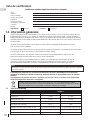
1.0 general information
For elevations between 2,000ft (610m) and 4,500ft (1372m) above sea level, this appliance must be de-rated by 10%
using the certified high altitude kit. When the appliance is installed at elevations above 4,500ft (1372m), and in the absence
of specific recommendations from the local authority having jurisdiction, the certified high altitude input rating shall be
reduced at the rate of 4% for each additional 1,000ft (305m).
Expansion / contraction noises during heating up and cooling down cycles are normal and to be expected.
This appliance is only for use with the type of gas indicated on the rating plate. This appliance is not convertible for
use with other gases, unless a certified kit is used.
The blower power cord must be connected into a properly grounded receptacle. The grounding prong must not
be removed from the cord plug.
This appliance is approved for closet or recessed installations, as well as for bathroom, bedroom and
bed-sitting room installations and is suitable for mobile home installations. The natural gas model can be installed
in a mobile home that is permanently positioned on its site and fueled with natural gas.
note:
The protective wrap on plated parts is best removed when the assembly is at room temperature but
this can be improved if the assembly is warmed, using a hair dryer or similar heat source.
This appliance is a decorative product. It is not a source of heat and not intended to burn solid fuel.
Batteries must be disposed of according to the local laws and regulations. Some batteries may be
recycled, and may be accepted for disposal at your local recycling center. Check with your
municipality for recycling instructions.
Les piles doivent être mises au rebut conformément aux lois et à la réglementation locales.
Certaines piles peuvent être recyclées et acceptées dans votre centre de recyclage local. Rensei-
gnez-vous auprès de votre municipalité au sujet des directives de recyclage.
Las baterías deben desecharse de acuerdo con las leyes y regulaciones locales. Algunas baterías
pueden reciclarse, y es posible que su centro de reciclado local las acepte para desecharlas.
Consulte en su municipalidad sobre las instrucciones para el reciclado.
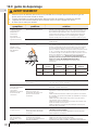
1.1 rates and efficiencies
GDS25-1
NG P
Altitude (FT) 0-2,000 0-2,000
Max. Input (BTU/HR) 24,500 23,000
Max. Output (BTU/HR) 19,000 16,000
Efficiency (w/the fan on) 80% 80%
Min. Inlet Gas Supply Pressure 4.5" Water Column (11mb) 11" Water Column (27mb)
Max. Inlet Gas Supply Pressure 13" Water Column (17mb) 13" Water Column (32mb)
Manifold Pressure (Under Flow Conditions) 3.5" Water Column (9mb) 10" Water Column (25mb)
A barrier designed to reduce the risk of burns from the hot viewing glass is provided with the appliance and must
be installed.
standard checklist
EN
W415-2207 / B / 02.05.18
5

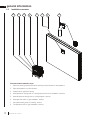
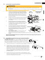
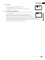
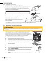
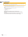
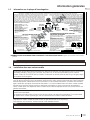
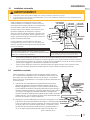
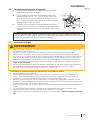
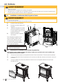
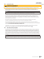
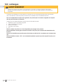
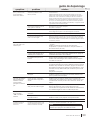
Recommended installation steps:
1. Determine venting requirements before deciding the final location of the appliance.
2. Place the appliance in its final position.
3. Create hole for appliance venting.
4. Install appliance venting (refer to “venting requirements” and “installation” sections).
5. Install all electrical wirings (refer to “wiring diagram” section).
6. Install gas lines (refer to “gas installation” section).
7. Complete finishing (refer to “finishing” section).
8. Test appliance (refer to “gas installation” section).
1.2 installation overview
SAFETY BARRIER
2
3
4
6
5
1
78
EN
W415-2207 / B / 02.05.18
6
general information

!
WARNING
• Always light the pilot whether for the first time or if the gas supply has run out, with the glass door opened
or removed.
• Provide adequate clearance for servicing and operating the appliance.
• Provide adequate ventilation.
• Never obstruct the front opening of the appliance.
• Objects placed in front of the appliance must be kept a minimum of 48” (121.9cm) from the front face of
the appliance.
• Surfaces around and especially above the appliance can become hot. Avoid contact when appliance is
operating.
• Fire risk. Explosion hazard.
• High pressure will damage valve. Disconnect gas supply piping before pressure testing gas line at test
pressures above 1/2 PISG (35mb). Close the manual shut-off valve before pressure testing gas line at test
pressures equal to or less than 1/2 PISG (35mb).
• Use only Wolf Steel approved optional accessories and replacement parts with this appliance using non-
listed accessories (blowers, doors, louvres, trims, gas components, venting components, etc.) could result
in a safety hazard and will void the warranty and certification.
• The appliance must not be operated at temperatures below freezing (32ºF/0ºC). Allow the appliance to
warm to above freezing prior to operation.
4.1
THIS GAS APPLIANCE MUST BE INSTALLED AND SERVICED BY A QUALIFIED INSTALLER to conform with local
codes. Installation practices vary from region to region and it is important to know the specifi cs that apply to your area, for
example in Massachusetts State:
• This product must be installed by a licensed plumber or gas fi tter when installed within the commonwealth of
Massachusetts.
• The appliance damper must be removed or welded in the open position prior to installation of an appliance insert or gas
log.
• The appliance off valve must be a “T” handle gas cock.
• The fl exible connector must not be longer than 36 inches (0.9m).
• A carbon monoxide detector is required in all rooms containing gas fi red appliances.
• The appliance is not approved for installation in a bedroom or bathroom unless the unit is a direct vent sealed
combustion product.
The installation must conform with local codes or, in absence of local
codes, the National Gas and Propane Installation Code CSA B149.1
in Canada, or the National Fuel Gas Code, ANSI Z223.1 / NFPA 54
in the United States. Suitable for mobile home installation if installed
in accordance with the current standard CAN/CSA Z240MH Series,
for gas equipped mobile homes, in Canada or ANSI Z223.1 and
NFPA 54 in the United States.
The appliance and its individual shutoff valve must be disconnected
from the gas supply piping system during any pressure testing
of that system at test pressures in excess of 1/2 psig (35 mb).
The appliance must be isolated from the gas supply piping system by closing its individual manual shutoff valve during any
pressure testing of the gas supply piping system at test pressures equal to or less than 1/2 psig (35 mb). When installed
with a blower or fan, the junction box must be electrically connected and grounded in accordance with local codes. In the
absence of local codes, use the current CSA C22.1 Canadian Electrical Code in Canada or the ANSI / NFPA 70 National
Electric Code in the United States. In the case where the blower is equipped with a power cord, it must be connected into a
properly grounded receptacle. The grounding prong must not be removed from the cord plug.
The following does not apply to inserts; as long as the required clearance to combustibles is maintained, the most desirable
and benefi cial location for an appliance is in the center of a building, thereby allowing the most effi cient use of the heat
created. The location of windows, doors and, the traffi c fl ow in the room where the appliance is to be located should be
considered. If possible, you should choose a location where the vent will pass through the house without cutting a fl oor or
roof joist. If the appliance is installed directly on carpeting, vinyl tile or other combustible material other than wood fl ooring, the
appliance shall be installed on a metal or wood panel extending the full width and depth, unless otherwise tested.
We suggest that our gas
hearth products be installed
and serviced by professionals
who are certied in the U.S.
by the National Fireplace
Institute
®
(NFI) as NFI Gas
Specialists
www.ncertied.org
general information
EN
W415-2207 / B / 02.05.18
7

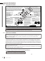
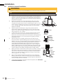
1.3 rating plate information
A 4"
B 2"
C 2"
TITLE: RATING PLATE,. GDS25 (SB)
REVISION: A: UPDATED CSA YEAR & DESCRIPTION || 08.16.17_C.L.
DWG#: W385-1962
DATE: 06.11.14
W385-1962 / A
NOT FOR USE WITH SOLID FUEL
GDS25
PAGE 1 OF 2
CONFORMS TO / CONFORME AUX: ANSI Z21.50-2016, CERTIFIED TO / CERTIFIE CSA 2.22-2016 VENTED DECORATIVE GAS APPLIANCE / FOYER À GAZ VENTILÉ.
MINIMUM CLEARANCE TO COMBUSTIBLE MATERIAL:
VENT TOP 2" TO CEILING FROM
VENT BOTTOM 1" STOVE TOP 48”
VENT SIDES 1"
WOLF STEEL LTD.
24 NAPOLEON ROAD, BARRIE. ONTARIO L4M 0G8 CANADA
UN COMBUSTIBLE SOLIDE NE DOIT PAS ETRE
UTILSE AVEC CET APPAREIL
EVENT SUPERIEUR 2" ENTRE LE DESSUS
DU FOYER
EVENT INFERIEUR 1" ET LE PLAFOND 48”
COTES DE L'EVENT 1"
A 4"
B 2"
C 2"
DEGAGEMENTS MINIMAUX DES MATERIAUX
COMBUSTIBLES:
SERIAL NUMBER / NO. DESERIE
WOLF STEEL LTD.
APPROVED FOR BEDROOM, BATHROOM & BEDSITTING ROOM INSTALLATION. SUITABLE
FOR MOBILE HOME INSTALLATION IF INSTALLED IN ACCORDANCE WITH THE CURRENT
STANDARD CAN/CSA Z240MH SERIES GAS EQUIPPED MOBILE HOMES, IN CANADA
OR IN THE UNITED STATES THE MANUFACTURED HOME CONSTRUCTION AND
SAFETY STANDARD, TITLE 24 CFR, PART 3280. WHEN THIS US STANDARD IS NOT
APPLICABLE USE THE STANDARD FOR FIRE SAFETY CRITERIA FOR MANUFAC-
TURED HOME INSTALLATIONS, SITES AND COMMUNITIES, ANSI / NFPA 501A. FOR
USE WITH BARRIER W010-3295. FOLLOW THE INSTALLATION INSTRUCTIONS
LOCATED IN THE INSTALLATION MANUAL
HOMOLOGUE POUR INSTALLATION DANS UNE CHAMBRE A COUCHER, UNE SALLE DE BAIN ET
UN STUDIO. APPROPRIE POUR INSTALLATION DANS UNE MAISON MOBILE SI SON
INSTALLATION CONFORME AUX EXIGENCES DE LA NORME CAN/CSA Z240MH SERIE DE
MAISONS MOBILES EQUIPEES AU GAZ, EN VIGUEUR AU CANADA OU AUX ETATS-UNIS
DE LA NORME DE SECURITE ET DE CONSTRUCTION DE MAISONS MANUFACTUREES,
TITRE 24 CFR, SECTION 3280. DANS LE CAS OU CETTE NORME D'ETATS-UNIS NE PEUT
ETRE APPLIQUEE, SE REFERER A LA NORME RELATIVE AU CRITERE DE MESURES DE
SECURITE CONTRE L'INCENDIE POUR LES INSTALLATIONS DANS LES MAISONS
MANUFACTURES, LES SITES ET LES COMMUNAUTES, ANSI/NFPA 501A. POUR UNE
UTILISER AVEC BARRIÈRE W010-3295. SUIVEZ LES INSTRUCTIONS D'INSTALLATION
SE TROUVENT DANS LE MANUEL D'INSTALLATION.
MANIFOLD PRESSURE: 3.5” W.C. (NG)
PRESSION AU COLLECTEUR: 3.5" D'UNE
COLONNE D'EAU(GN)
MIN SUPPLY PRESSURE: 4.5" W.C.(NG)
PRESSION D'ALIMENTATION MIN: 4.5"
D'UNE COLONNE D'EAU (GN)
MAX. SUPPLY PRESSURE: 7" W.C. (NG)
PRESSION D'ALIMENTATION MAX: 7"
D'UNE COLONNE D'EAU (GN)
AFUE: 64%
MANIFOLD PRESSURE: 10” W.C. (LP)
PRESSION AU COLLECTEUR: 10" D'UNE
COLONNE D'EAU(P)
MIN SUPPLY PRESSURE: 11" W.C.(LP)
PRESSION D'ALIMENTATION MIN: 11"
D'UNE COLONNE D'EAU (P)
MAX. SUPPLY PRESSURE: 13" W.C. (LP)
PRESSION D'ALIMENTATION MAX: 13"
D'UNE COLONNE D'EAU (P)
AFUE: 64%
GDS25N MODEL GDS25P
0-2000ft 2000-4500ft ALTITUDE / ELEVATION 0-2000ft 2000-4500ft
24,500 BTU/h 22,000 BTU/h INPUT / ALIMENTATION 23,000 BTU/h 20,000 BTU/h
19,000 BTU/h 16,000 BTU/h REDUCED INPUT / 16,000 BTU/h 14,000 BTU/h
ALIMENTATION REDUITE
9700539 (WSL) 4001657 (NGZ)
4001658 (NAC) 4001659 (WUSA)
FOR USE WITH GLASS DOORS CERTIFIED
WITH THIS UNIT ONLY.
WARNING: DO NOT ADD ANY MATERIAL TO
THE APPLIANCE, WHICH WILL COME IN
CONTACT WITH THE FLAMES, OTHER THAN
THAT SUPPLIED BY THE MANUFACTURER
WITH THE APPLIANCE.
ELECTRICAL RATING: 115V 1.5AMP 60HZ
THE APPLIANCE MUST BE VENTED USING
THE APPROPRIATE WOLF STEEL VENT
KITS. SEE OWNERS INSTALLATION MANUAL
FOR VENTING SPECIFICS. MINIMUM AND
MAXIMUM VERTICAL VENT LENGTHS ARE 3
FEET AND 40 FEET RESPECTIVELY.
MINIMUM AND MAXIMUM HORIZONTAL
VENT LENGTHS ARE 10 INCHES AND 20
FEET RESPECTIVELY. PROPER REINSTAL-
LATION AND RESEALING IS NECESSARY
AFTER SERVICING THE VENT-AIR INTAKE
SYSTEM.
UTILISER AVEC LES PORTES VITREES
HOMOLOGUEES SEULEMENT AVEC CETTE
UNITE.
AVERTISSEMENT: N'AJOUTEZ PAS A CET
APPAREIL AUCUN MATERIAU DEVANT
ENTRER EN CONTACT AVEC LES FLAMMES
AUTRE QUE CELUI QUI EST FOURNI AVEC
CET APPAREIL PAR LE FABRICANT.
CLASS.: 115V 1.5AMP 60HZ L'APPAREIL
DOIT EVACUER SES GAZ EN UTILISANT
L'ENSEMBLE D'EVACUATION PROPRE A
WOLF STEEL. REFERER AU MANUEL
D'INSTALLATION DE PROPRIETAIRE POUR
L'EVACUATION PRECISE. LES LONGUEURS
VERTICALES MINIMALES ET MAXIMALES
SONT3 PIEDS ET 40 PIEDS
RESPECTIVEMENT.
LES LONGUEURS HORIZONTALES MINIMALES ET
MAXIMALES SONT 10 POUCES ET 20 PIEDS
RESPECTIVEMENT.
IL EST IMPORTANT DE BIEN REINSTALLER ET
RESCELLER L'EVENT APRES AVOIR ASSURE LE
MAINTIEN DU SYSTEME DE PRISE D'AIR.
MATERIAL: CLASS IIIA-2 PERMANENT LABEL, WATERPROOF, 10 MIL VELVET GLOSS LEXAN
HOLE TO BE 0.250ӯ
BLACK ON WHITE BACKGROUND
MAX OVERALL DECAL SIZE: 8.5"x4.75"
SERIAL NUMBERS TO BE ASCENDING FROM GDS25/CDVS25007100
A
This illustration is for referece only. Refer to the rating plate on the appliance for accurate information.
SAMPLE
The rating plate must remain with the appliance at all times. It must not be removed.
note:
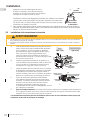
1.4 mobile home installation
This appliance must be installed in accordance with the manufacturer’s instructions and the Manufactured
Home Construction and Safety Standard, Title 24 CFR, Part 3280, in the United States or the Mobile Home
Standard, CAN/CSA Z240 MH Series, in Canada. This appliance is only for use with the type(s) of gas
indicated on the rating plate.
This mobile/manufactured home listed appliance comes factory equipped with a means to secure the appliance. Built
in appliances are equipped with 1/4” (6.4mm) diameter holes located in the front left and right corners of the base.
Use appropriate fasteners, inserted through the holes in the base to secure. For free standing products contact your
local authorized dealer / distributor for the appropriate securing kit. For mobile home installations, the appliance must
be fastened in place. It is recommended that the appliance be secured in all installations. Always turn off the pilot and
the fuel supply at the source, prior to moving the mobile home. After moving the mobile home and prior to lighting the
appliance, ensure that the logs are positioned correctly.
This appliance is certifi ed to be installed in an aftermarket permanently located, manufactured (mobile) home,
where not prohibited by local codes.
This appliance is only for use with the type of gas indicated on the rating plate. This appliance is not convertible
for use with other gases, unless a certifi ed kit is used.
Conversion Kits
This appliance is fi eld convertible between Natural Gas (NG) and Propane (P).
To convert from one gas to another, consult your Authorized dealer/distributor.
20.1
note:
Conversion kits are not available for Vent Free appliances.
EN
W415-2207 / B / 02.05.18
8
general information

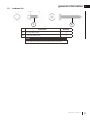
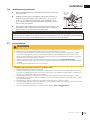
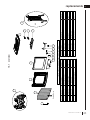
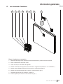
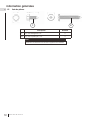
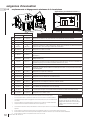
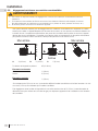
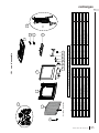
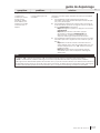
1.5 hardware list
note:
Description Quantity
1
1/4” Hex Head Screw 3
2
1 3/4” Pan Head Screw 4
Only fasteners supplied with the appliance are illustrated.
1
2
general information
EN
W415-2207 / B / 02.05.18
9

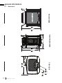
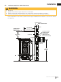
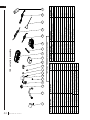
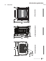
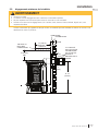
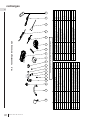
1.6 dimensions
25 5/8"
651mm
23 5/8"
600mm
17 1/2"
445mm
23 1/2"
597mm
12 3/4"
324mm
Ø
4"
102mm
Ø
7"
178mm
SAFETY BARRIER
FRONT VIEW
RIGHT SIDE VIEW
TOP VIEW
EN
W415-2207 / B / 02.05.18
10
general information

2.0 venting requirements
7.1B
!
WARNING
• Risk of fi re. Maintain specifi ed air space clearances to vent pipe and appliance.
• If venting is included with spacers, the vent system must be supported every 3’(0.9m) for both vertical and horizontal runs.
Use support ring assembly W010-0067 or equivalent non-combustible strapping to maintain the minimum clearance to
combustibles for both vertical and horizontal runs. Spacers are attached to the inner pipe at predetermined intervals to
maintain an even air gap to the outer pipe. This gap is required for safe operation. A spacer is required at the start, middle,
and end of each elbow to ensure this gap is maintained. These spaces must not be removed.
This appliance uses a 4” (102mm) exhaust / 7” (178mm) air intake vent pipe system. Refer to the section applicable
to your installation.
For safe and proper operation of the appliance, follow the venting instructions exactly. Deviation from the minimum vertical
vent length can create diffi culty in burner start-up and/or carboning. Under extreme vent confi gurations, allow several minutes
(5-15) for the fl ame to stabilize after ignition. Although not a requirement, it is recommended for vent lengths that pass through
unheated spaces (attics, garages, crawl spaces) be insulated with the insulation wrapped in a protective sleeve to minimize
condensation. Provide a means for visually checking the vent connection to the appliance after the appliance is installed. Use a
fi restop, vent pipe shield or attic insulation shield when penetrating interior walls, fl oor or ceiling.
The vent terminal may be painted with a high temperature paint to match exterior colours. Use an outdoor paint suitable for
400°F (200°C). Application and performance of paint is the consumer’s responsibility. Spot testing is recommended.
For vent systems that provide seals on the inner exhaust fl ue, only the outer air intake joints must be sealed using a red high
temperature silicone (RTV). This same sealant may be used on both the inner exhaust and outer intake vent pipe joints of all
other approved vent systems except for the exhaust vent pipe connection to the appliance fl ue collar which must be sealed
using the black high temperature sealant Mill Pac. High temperature sealant must be ordered separately.
For optimum fl ame appearance and appliance performance, keep the vent length and number of elbows to a minimum.
The air terminal must remain unobstructed at all times. Examine the air terminal at least once a year to verify that
it is unobstructed and undamaged.
Rigid and fl exible venting systems must not be combined. Different venting manufacturer components must not
be combined.
These vent kits allow for either horizontal or vertical venting of the appliance. The maximum allowable horizontal run is 20
feet (6.1m). The maximum allowable vertical vent length is 40 feet (12.2m). The maximum number of vent connections is two
horizontally or three vertically (excluding the appliance and the air terminal connections) when using fl exible venting.
Horizontal runs may have a 0” rise per foot or 0mm rise per meter however for optimum performance it is recommended
that all horizontal runs have a minimum 1/4” rise per foot or 21mm rise per meter using fl exible venting. For safe and proper
operation of the appliance, follow the venting instructions exactly.
A terminal shall not terminate directly above a sidewalk or paved driveway which is located between two single family dwellings
and serves both dwellings. Local codes or regulations may require different clearances.
Do not allow the inside liner to bunch up on horizontal or vertical runs and elbows. Keep it pulled tight. A 1¼” (31.8mm) air gap
all around between the inner liner and outer liner is required for safe operation.
Vent
Manufacturer
Starter Adapter Part Number Supplier Website
Duravent W175-0053 Wolf Steel www.duravent.com
Amerivent 4DSC-N2 American Metal www.americanmetalproducts.com
Direct Temp 4DT-AAN Selkirk www.selkirkcorp.com
SuperSeal 4DNA Metal-Fab www.mtlfab.com
Use only Wolf Steel, Simpson Dura-Vent, Selkirk Direct Temp, American Metal Amerivent or Metal-Fab venting components.
Minimum and maximum vent lengths, for both horizontal and vertical installations, clearances from vent pipes to combustibles
and air terminal locations as set out in this manual apply to all vent systems and must be adhered to. For Simpson Dura-Vent,
Selkirk Direct Temp, American Metal Amerivent and Metal-Fab, follow the installation procedure provided with the venting
components or on the website for your venting supplier. A starter adaptor must be used with the following vent systems and
may be purchased from the corresponding supplier:
note:
If for any reason the vent air intake system is disassembled, re-install per the instructions provided for the initial installation.
note:
This appliance must be installed with a continuous connection of exhaust and air intake vent pipes. Utilizing
alternate constructions such as a chimney as part of the vent system is not permitted.
This template must be used in conjunction with templates 7.1.1 or 7.1.2, depending on
termination shape (i.e. round, or round and square). See appropriate templates folder.
7.1.1
When using Wolf Steel venting components, use only approved Wolf Steel rigid / fl exible components with the following ter-
mination kits: wall terminal kit GD-222, GD-222R, or 1/12 to 7/12 pitch roof terminal kit GD-110, 8/12 to 12/12 roof terminal
kit GD-111, fl at roof terminal kit GD-112 or periscope kit GD-201 (for wall penetration below grade). With fl exible venting, in
conjunction with the various terminations, use either the 5 foot (1.5m) vent kit GD-220 or the 10 foot (3.1m) vent kit GD-330.
For stoves only: wall terminal kit GD-175 (venting included).
EN
W415-2207 / B / 02.05.18
11

7.1B
!
WARNING
• Risk of fi re. Maintain specifi ed air space clearances to vent pipe and appliance.
• If venting is included with spacers, the vent system must be supported every 3’(0.9m) for both vertical and horizontal runs.
Use support ring assembly W010-0067 or equivalent non-combustible strapping to maintain the minimum clearance to
combustibles for both vertical and horizontal runs. Spacers are attached to the inner pipe at predetermined intervals to
maintain an even air gap to the outer pipe. This gap is required for safe operation. A spacer is required at the start, middle,
and end of each elbow to ensure this gap is maintained. These spaces must not be removed.
This appliance uses a 4” (102mm) exhaust / 7” (178mm) air intake vent pipe system. Refer to the section applicable
to your installation.
For safe and proper operation of the appliance, follow the venting instructions exactly. Deviation from the minimum vertical
vent length can create diffi culty in burner start-up and/or carboning. Under extreme vent confi gurations, allow several minutes
(5-15) for the fl ame to stabilize after ignition. Although not a requirement, it is recommended for vent lengths that pass through
unheated spaces (attics, garages, crawl spaces) be insulated with the insulation wrapped in a protective sleeve to minimize
condensation. Provide a means for visually checking the vent connection to the appliance after the appliance is installed. Use a
fi restop, vent pipe shield or attic insulation shield when penetrating interior walls, fl oor or ceiling.
The vent terminal may be painted with a high temperature paint to match exterior colours. Use an outdoor paint suitable for
400°F (200°C). Application and performance of paint is the consumer’s responsibility. Spot testing is recommended.
For vent systems that provide seals on the inner exhaust fl ue, only the outer air intake joints must be sealed using a red high
temperature silicone (RTV). This same sealant may be used on both the inner exhaust and outer intake vent pipe joints of all
other approved vent systems except for the exhaust vent pipe connection to the appliance fl ue collar which must be sealed
using the black high temperature sealant Mill Pac. High temperature sealant must be ordered separately.
For optimum fl ame appearance and appliance performance, keep the vent length and number of elbows to a minimum.
The air terminal must remain unobstructed at all times. Examine the air terminal at least once a year to verify that
it is unobstructed and undamaged.
Rigid and fl exible venting systems must not be combined. Different venting manufacturer components must not
be combined.
These vent kits allow for either horizontal or vertical venting of the appliance. The maximum allowable horizontal run is 20
feet (6.1m). The maximum allowable vertical vent length is 40 feet (12.2m). The maximum number of vent connections is two
horizontally or three vertically (excluding the appliance and the air terminal connections) when using fl exible venting.
Horizontal runs may have a 0” rise per foot or 0mm rise per meter however for optimum performance it is recommended
that all horizontal runs have a minimum 1/4” rise per foot or 21mm rise per meter using fl exible venting. For safe and proper
operation of the appliance, follow the venting instructions exactly.
A terminal shall not terminate directly above a sidewalk or paved driveway which is located between two single family dwellings
and serves both dwellings. Local codes or regulations may require different clearances.
Do not allow the inside liner to bunch up on horizontal or vertical runs and elbows. Keep it pulled tight. A 1¼” (31.8mm) air gap
all around between the inner liner and outer liner is required for safe operation.
Vent
Manufacturer
Starter Adapter Part Number Supplier Website
Duravent W175-0053 Wolf Steel www.duravent.com
Amerivent 4DSC-N2 American Metal www.americanmetalproducts.com
Direct Temp 4DT-AAN Selkirk www.selkirkcorp.com
SuperSeal 4DNA Metal-Fab www.mtlfab.com
Use only Wolf Steel, Simpson Dura-Vent, Selkirk Direct Temp, American Metal Amerivent or Metal-Fab venting components.
Minimum and maximum vent lengths, for both horizontal and vertical installations, clearances from vent pipes to combustibles
and air terminal locations as set out in this manual apply to all vent systems and must be adhered to. For Simpson Dura-Vent,
Selkirk Direct Temp, American Metal Amerivent and Metal-Fab, follow the installation procedure provided with the venting
components or on the website for your venting supplier. A starter adaptor must be used with the following vent systems and
may be purchased from the corresponding supplier:
note:
If for any reason the vent air intake system is disassembled, re-install per the instructions provided for the initial installation.
note:
This appliance must be installed with a continuous connection of exhaust and air intake vent pipes. Utilizing
alternate constructions such as a chimney as part of the vent system is not permitted.
This template must be used in conjunction with templates 7.1.1 or 7.1.2, depending on
termination shape (i.e. round, or round and square). See appropriate templates folder.
EN
W415-2207 / B / 02.05.18
12
venting requirements

24” (61cm)
MAXIMUM
24” (61cm) MIN.
REGARDLESS OF
HORIZONTAL VENT
LENGTH
40FT (12m)
MAX
3FT (1m)
MIN
16” (40.6cm)
25 5/8”
(65.1cm)
25 5/8”
(65.1cm)
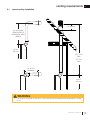
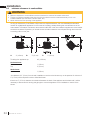
2.1 typical venting installation
• The maximum horizontal run with a 57” (1.45m) vertical rise immediately above the appliance is 20 feet
(6.1m).
!
WARNING
venting requirements
EN
W415-2207 / B / 02.05.18
13

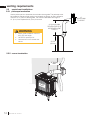
Use the periscope kit to locate the air termination above grade. The periscope must
be installed so that when fi nal grading is completed, the bottom air slot is located a
minimum of 12” (305mm) above grade. The maximum allowable vent length is
10’ (3.1m) for a fi replace and 8’ (2.4m) for a stove.
8.2
2.2 special vent installations
2.2.1 periscope termination
2.2.2 corner termination
12”
(305mm) MIN
TO GRADE
24” (610mm)
MAX.
SAFETY
BARRIER
25 5/8”
(651mm)
24” (610mm) MIN.
REGARDLESS OF OF
HORIZONTAL VENT
LENGTH
• Below grade installation maximum
8ft (2.4m) vent length.
• Use GD201 periscope kit.
• Horizontal run not to exceed verti-
cal rise.
!
WARNING
EN
W415-2207 / B / 02.05.18
14
venting requirements

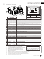
2.3 vent terminal clearances
Covered balcony applications
††*
Q
MIN
R
MAX
MAX
R
= 3 feet
(0.9m)
= 2 x
≤ 15 feet
(4.6m)
Q
ACTUAL
R
Q
S
G
P
INSTALLATIONS
CANADA U.S.A.
A
12” (30.5cm) 12” (30.5cm) Clearance above grade, veranda porch, deck or balcony.
B
12” (30.5cm)
Δ
9” (229mm)
Δ
Clearance to windows or doors that open.
C
12” (30.5cm)* 12” (30.5cm)* Clearance to permanently closed windows.
D
18”
(45.7cm)**
18”
(45.7cm)**
Vertical clearance to ventilated soffi ts located above the terminal within a horizontal distance of 2’
(0.6m) from the center line of the terminal.
E
12” (30.5cm)** 12” (30.5cm)** Clearance to unventilated soffi t.
F
0” (0mm) 0” (0mm) Clearance to an outside corner wall.
G
0” (0mm)*** 0” (0mm)***
Clearance to an inside non-combustible corner wall or protruding non-combustible obstructions (chimney, etc.).
2” (51mm)*** 2” (51mm)*** Clearance to an inside combustible corner wall or protruding combustible obstructions (vent chase, etc.).
H
3’(0.9m) 3’(0.9m)****
Clearance to each side of the center line extended above the meter / regulator assembly to a maxi-
mum vertical distance of 15’ (4.6m).
I
3’ (0.9m) 3’ (0.9m)**** Clearance to a service regulator vent outlet.
J
12” (30.5cm) 9” (229mm) Clearance to a non-mechanical air supply inlet to the building or a combustion air inlet to any other appliance.
K
6’ (1.8m) 3’ (0.9m) † Clearance to a mechanical air supply inlet.
L
7’ (2.1m) ‡ 7’ (2.1m) **** Clearance above a paved sidewalk or paved driveway located on public property.
M
12” (30.5cm)†† 12” (30.5cm)**** Clearance under a veranda, porch or deck.
N
16” (40.6cm) 16” (40.6cm) Clearance above the roof.
O
2’ (0.6m)†* 2’ (0.6m) †* Clearance from an adjacent wall including neighbouring buildings.
P
8’ (2.4m) 8’ (2.4m)
Roof must be non-combustible without openings.
Q
3’ (0.9m) 3’ (0.9m) See chart for wider wall dimensions.
R
6’ (1.8m) 6’ (1.8m)
See chart for deeper wall dimensions. The terminal shall not be installed on any wall that has an
opening between the terminal and the open side of the structure.
S
12” (30.5cm) 12” (30.5cm) Clearance under a covered balcony
Δ The terminal shall not be located less than 6 feet under a window that opens on a horizontal plane in a structure with three walls and a roof.
* Recommended to prevent condensation on windows and thermal breakage
** It is recommended to use a heat shield and to maximize the distance to vinyl clad soffi ts.
*** The periscope requires a minimum 18 inches clearance from an inside corner.
**** This is a recommended distance. For additional requirements, check local codes.
† 3 feet above if within 10 feet horizontally.
‡ A vent shall not terminate where it may cause hazardous frost or ice accumulations on adjacent property surfaces.
†† Permitted only if the veranda, porch, or deck is fully open on a minimum of two sides beneath the fl oor.
†* Recommended to prevent recirculation of exhaust products. For additional requirements, check local codes.
††* Permitted only if the balcony is fully open on a minimum of one side.
Clearances are to be in accordance with local
installation codes and the requirements of the gas
supplier. In their absence, clearances are to be as
listed above and are based on national codes.
note:
9.1A
note:
Wall terminals are for illustration purposes only. Size and
shapes may vary.
venting requirements
EN
W415-2207 / B / 02.05.18
15

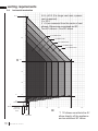
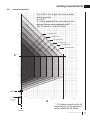
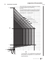
2.4 horizontal termination
0’
0’
Centre of
Base of Air
Collar
10’
10’
15’
15’
20’
25’
20’
30’
5’
5’
1 1/2 elbow zone*
2 1/2 elbow zone
3 1/2 elbow zone
4 1/2 elbow zone
5 1/2 elbow zone
H
V
V+H ≤ 40 ft. (For longer vent runs, a power
vent is required).
H ≤ 20 ft.
V + H are measured from the centre of vent
elbows. Elbows are considered as 90º.
Two 45º elbows = One 90º elbow.
4”
MAXIMUM
24”
MAXIMUM
10”
39’ 2”
57”
24”
MINIMUM
* 1 1/2 elbows constitute the 45°
elbow directly off the appliance
and an additional 90° elbow.
EN
W415-2207 / B / 02.05.18
16
venting requirements

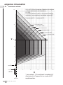
2.5 vertical termination
0’
0’
Centre of
Base of Air
Collar
10’
10’
15’
15’
20’
25’
20’
30’
40’
5’
4”
MINIMUM
5’
1 1/2 elbow zone*
2 1/2 elbow zone
3 1/2 elbow zone
4 1/2 elbow zone
5 1/2 elbow zone
6 1/2 elbow zone
H
V
V+H ≤ 40 ft. (For longer vent runs, a power
vent is required).
H ≤ 20 ft.
V + H are measured from the centre of vent
elbows. Elbows are considered as 90º.
Two 45º elbows = One 90º elbow.
3’
MINIMUM
* 1 1/2 elbows constitute the 45°
elbow directly off the appliance
and an additional 90° elbow.
venting requirements
EN
W415-2207 / B / 02.05.18
17

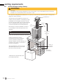
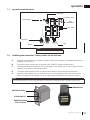
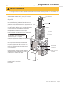
2.6 vertical through existing chimney
!
WARNING
• Risk of fi re.
• Co-axial to co-linear venting confi gurations must only be used in a non-combustible chimney or enclosure.
Installation in a combustible enclosure could result in a fi re.
7.6
This appliance is designed to be attached to a 3” (76.2mm) co-linear aluminum fl ex vent system running the full
length of a masonry chimney.
The fl ex liners accommodate any contours of a
masonry chimney, however, it is necessary to keep
the fl exible liners as straight as possible. The inlet
air collar of the termination cap must be connected
to the air intake fl ex liner and the exhaust collar
must be connected to the exhaust fl exible liner.
Both Simpson Duravent and Selkirk co-linear to
co-axial adaptors have been approved on this
appliance
Follow vent manufacturer’s installation instructions.
Different manufacturer’s venting
components must not be combined.
Once the preferred manufacturer’s
appliance adaptor has been attached, the
remainder of the system must be that of
the same manufacturer.
The only exception to this rule is to use
Wolf Steel’s approved 3” (76.2mm) fl ex
liner and co-linear termination.
AIR
INTAKE
EXHAUST
FLUE
FLEX
LINER
* 40 FT (12.2m)
MAX.
10 FT (3.1m)
MIN
COAXIAL TO
CO-LINEAR
ADAPATOR
APPLIANCE
VENT ADAPTOR
TERMINATION
* Measured from appliance fl ue collar
to termination fl ue collar
note:
A vent adaptor will be required directly off the appliance.
EN
W415-2207 / B / 02.05.18
18
venting requirements

3.0 installation
42.1
!
WARNING
• Ensure to unpack all loose materials from inside the fi rebox prior to connecting the gas and electrical supply
• If your appliance is supplied with a remote, ensure the remote receiver is in the “OFF” position prior
to connecting the gas and electrical supply to the appliance.
• For safe and proper operation of the appliance, follow the venting instructions exactly.
• The appliance exhaust fl ue collar must be sealed using Mill Pac. All exhaust and intake vent pipe joints
must be sealed using red RTV high temp silicone sealant (W573-0002) (not supplied) or black high temp Mill
Pac (W573-0007) (not supplied).
• If using pipe clamps to connect rigid vent components, a minimum of 3 screws must also be used to ensure
the connection cannot slip off.
• Do not clamp the fl exible vent pipe.
• Risk of fi re, explosion, or asphyxiation. Improper support of the entire venting system may allow vent to sag
and separate. Use vent run supports and connect vent sections per installation instructions.
• Risk of fi re, do not allow loose materials or insulation to touch the vent pipe. Remove insulation to allow for the
installation of the attic shield and to maintain clearances to combustibles.
• Do not fi ll the space between the vent pipe and enclosure with any type of material. Do not pack insulation
or combustibles between ceiling fi restops. Always maintain specifi ed clearances around venting and fi restop
systems. Install wall shields and fi restops as specifi ed. Failure to keep insulation or other materials away from
vent pipe may cause fi re.
EN
W415-2207 / B / 02.05.18
19

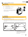
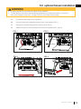
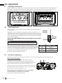
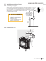
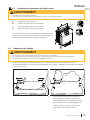
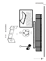
16.5
This application occurs when venting through a roof. Installation kits for
various roof pitches are available from your authorized dealer / distributor.
See the “accessories” section to order specifi c kits required.
A. Determine the air terminal location, cut and frame a square opening,
as illustrated, in the ceiling and the roof to provide the minimum 1"
(25mm) clearance between the vent pipe and any combustible material.
Try to center the vent pipe location midway between two joists to
prevent having to cut them. Use a plumb bob to line up the center of
the openings. A vent pipe shield will prevent any materials such as
insulation, from fi lling up the 1" (25mm) air space around the pipe. Nail
headers between the joist for extra support.
B. Apply a bead of caulking (not supplied) to the framework or to the
Wolf Steel vent pipe shield plate or equivalent (in the case of a fi nished
ceiling), and secure over the opening in the ceiling. A fi restop must be
placed on the bottom of each framed opening in a roof or ceiling that
the venting system passes through. Apply a bead of caulking all around
and place a fi restop spacer over the vent shield to restrict cold air from
being drawn into the room or around the fi replace. Ensure that both
spacer and shield maintain the required clearance to combustibles.
Once the vent pipe is installed in its fi nal position, apply Mill Pac sealant
(W573-0007) (not supplied) or red RTV silicone (W573-0002) (not
supplied) between the pipe and the fi restop assembly.
C. In the attic, slide the vent pipe collar down to cover up the open end
of the shield and tighten. This will prevent any materials, such as
insulation, from fi lling up the 1" (25mm) air space around the pipe.
Caulking
Vent Pipe
Shield
Vent
Pipe
Shield
Vent
Pipe
Collar
Firestop
underside
of joist
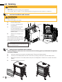
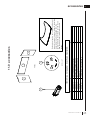
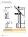
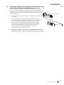
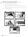
3.2 vertical installation
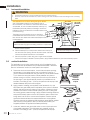
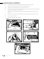
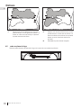
3.1 horizontal installation
16.4A
This application occurs when venting through an exterior
wall. Having determined the correct height for the air
terminal location, cut and frame a hole in the exterior wall,
as illustrated, to accommodate the fi restop assembly. Dry
fi t the fi restop assembly before proceeding to ensure the
brackets on the rear surface fi t to the inside surface of the
horizontal framing.
The length of the vent shield may be cut shorter for
combustible walls that are less than 8 1/2” (215.9mm)
thick but the vent shield must extend the full depth of the
combustible wall.
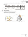
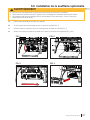
A. Assemble the shield to the spacer as shown, using the 3
shorter screws supplied.
B. Place the fi restop top so that the vent shield covers the top of
the vent within the opening. Ensure that both spacer and shield
maintain the required clearance to combustibles.
C. Secure the spacer in place using the 4 longer screws supplied.
Once the vent pipe is installed in its fi nal position, apply sealant between the pipe and the fi restop spacer.
• The fi restop assembly must be installed with the vent shield to the top.
• Terminals must not be recessed into a wall or siding more than the depth of the return fl ange of the mounting
plate.
!
WARNING
Do not fi ll the air space between the fi restop spacer and the
exterior wall with any type of insulating material (i.e. spray foam).
note:
DETERMINE
THE
CORRECT
HEIGHT
CAULKING
FIRESTOP
SPACER
VENT
SHIELD
FINISHING
MATERIAL
CAULKING
note:
The above is for illustration purposes only. Vents
do not always pass through center of frame.
ADD
WIDTH
ADD
HEIGHT
10 11/16”
(27.14cm)
WIDE
10 11/16”
(27.14cm)
HIGH
EN
W415-2207 / B / 02.05.18
20
installation
Page is loading ...
Page is loading ...
Page is loading ...
Page is loading ...
Page is loading ...
Page is loading ...
Page is loading ...
Page is loading ...
Page is loading ...
Page is loading ...
Page is loading ...
Page is loading ...
Page is loading ...
Page is loading ...
Page is loading ...
Page is loading ...
Page is loading ...
Page is loading ...
Page is loading ...
Page is loading ...
Page is loading ...
Page is loading ...
Page is loading ...
Page is loading ...
Page is loading ...
Page is loading ...
Page is loading ...
Page is loading ...
Page is loading ...
Page is loading ...
Page is loading ...
Page is loading ...
Page is loading ...
Page is loading ...
Page is loading ...
Page is loading ...
Page is loading ...
Page is loading ...
Page is loading ...
Page is loading ...
Page is loading ...
Page is loading ...
Page is loading ...
Page is loading ...
Page is loading ...
Page is loading ...
Page is loading ...
Page is loading ...
Page is loading ...
Page is loading ...
Page is loading ...
Page is loading ...
Page is loading ...
Page is loading ...
Page is loading ...
Page is loading ...
Page is loading ...
Page is loading ...
Page is loading ...
Page is loading ...
Page is loading ...
Page is loading ...
Page is loading ...
Page is loading ...
Page is loading ...
Page is loading ...
Page is loading ...
Page is loading ...
Page is loading ...
Page is loading ...
Page is loading ...
Page is loading ...
Page is loading ...
Page is loading ...
Page is loading ...
Page is loading ...
Page is loading ...
Page is loading ...
Page is loading ...
Page is loading ...
Page is loading ...
Page is loading ...
Page is loading ...
Page is loading ...
-
 1
1
-
 2
2
-
 3
3
-
 4
4
-
 5
5
-
 6
6
-
 7
7
-
 8
8
-
 9
9
-
 10
10
-
 11
11
-
 12
12
-
 13
13
-
 14
14
-
 15
15
-
 16
16
-
 17
17
-
 18
18
-
 19
19
-
 20
20
-
 21
21
-
 22
22
-
 23
23
-
 24
24
-
 25
25
-
 26
26
-
 27
27
-
 28
28
-
 29
29
-
 30
30
-
 31
31
-
 32
32
-
 33
33
-
 34
34
-
 35
35
-
 36
36
-
 37
37
-
 38
38
-
 39
39
-
 40
40
-
 41
41
-
 42
42
-
 43
43
-
 44
44
-
 45
45
-
 46
46
-
 47
47
-
 48
48
-
 49
49
-
 50
50
-
 51
51
-
 52
52
-
 53
53
-
 54
54
-
 55
55
-
 56
56
-
 57
57
-
 58
58
-
 59
59
-
 60
60
-
 61
61
-
 62
62
-
 63
63
-
 64
64
-
 65
65
-
 66
66
-
 67
67
-
 68
68
-
 69
69
-
 70
70
-
 71
71
-
 72
72
-
 73
73
-
 74
74
-
 75
75
-
 76
76
-
 77
77
-
 78
78
-
 79
79
-
 80
80
-
 81
81
-
 82
82
-
 83
83
-
 84
84
-
 85
85
-
 86
86
-
 87
87
-
 88
88
-
 89
89
-
 90
90
-
 91
91
-
 92
92
-
 93
93
-
 94
94
-
 95
95
-
 96
96
-
 97
97
-
 98
98
-
 99
99
-
 100
100
-
 101
101
-
 102
102
-
 103
103
-
 104
104


NAPOLEON GDS25 Owner's manual
- Type
- Owner's manual
- This manual is also suitable for
Ask a question and I''ll find the answer in the document
Finding information in a document is now easier with AI
in other languages
- français: NAPOLEON GDS25 Le manuel du propriétaire
Related papers
-
NAPOLEON GDS20 Owner's manual
-
-
-
-
NAPOLEON B35NT User manual
-
NAPOLEON TLV50 User manual
-
Napoleon Fireplaces The Bayfield GDS25N User manual
-
Napoleon Fireplaces GDS25P User manual
-
-
Other documents
-
Cateye HL-EL520 User manual
-
Essence ESS45 Installation And Operating Instructions Manual
-
Kozyheat Alpha 36S Owner's manual
-
-
-
-
-
Valor 1195CFK Owner's manual
-
-