Samsung AR12TSHZRWKXRC Installation guide

Category
Split-system air conditioners
Type
Installation guide
Air conditioner
Installation manual
AR**TSHZ*** / AR**TSEA*** / AR**TSFA***/ AR**TSHY***/
AR**TSFC***
Thank you for purchasing this Samsung air conditioner.
Before operating this unit, please read this installation manual carefully and retain it for
future reference.
DB68-08810A-00
2
English
Contents
Safety Information 3
Installation 4
Preparation 4
Step 1.1 Viewing the typical installation 4
Step 1.2 Choosing the installation location 5
Step 1.3 Unpacking 8
Step 1.4 Preparing materials and tools 9
Indoor Unit Installation 11
Step 2.1 Attaching the mounting bracket to the wall 11
Step 2.2 Drilling the wall penetration 11
Step 2.3 Connecting the refrigerant pipes 12
Step 2.4 Connecting the power and communication cables 13
Step 2.5 Optional: Extending the power cable 15
Step 2.6 Connecting the drain hose 16
Step 2.7 Taping the pipes, cables, and drain hose 17
Outdoor Unit Installation 18
Step 3.1 Mounting the outdoor unit 18
Step 3.2 Connecting the cables and the pipes 19
Installation Inspection and Testing 21
Step 4.1 Performing a drain leak test 21
Step 4.2 Performing the gas leak tests 21
Step 4.3 Evacuating the system 22
Step 4.4 Adding refrigerant (if needed) 23
Step 4.5 Preparing the system for commissioning 23
Step 4.6 Commissioning the unit 23
Step 4.7 Performing final checks and trial operation 24
Safety Information
3
English
Safety Information
Safety Information
Safety Information
WARNING: Read This Manual
Read and follow all safety information and instructions
before installation, use, or maintenance of this
appliance. Incorrect installation, use, or maintenance
of this appliance can result in death, serious injury, or
property damage. Keep these instructions with this
appliance. This manual is subject to change. For the
latest version,
visit www.samsung.com.
Notices and notes
To make you aware of safety messages and highlighted
information, we use the following notices and notes
throughout this manual:
WARNING
Hazards or unsafe practices that may result in severe personal
injury or death.
CAUTION
Hazards or unsafe practices that may result in minor personal
injury or property damage.
IMPORTANT
Information of special interest
NOTE
Supplementary information that may be useful
The user and installer guides
should be read carefully.
The user and installer guides
should be read carefully.
WARNING
The installation and testing of this appliance must be
performed by a qualified technician.
The instructions in this manual are not intended as a
substitute for proper training or adequate experience in
the safe installation of the appliance.
Always install the air conditioner in compliance with current
local, state, and federal safety standards.
General information
The air conditioner should be used only for the
applications for which it has been designed: the indoor
unit is not suitable to be installed in areas used for
laundry.
Installation of the product
Our units must be installed in compliance with the
spaces indicated in the installation manual to ensure
either accessibility from both sides or ability to perform
routine maintenance and repairs. The units’ components
must be accessible and that can be disassembled in
conditions of complete safety either for people or things.
For this reason, where it is not observed as indicated
into the Installation Manual, the cost necessary to reach
and repair the unit (in safety, as required by current
regulations in force) with slings, trucks, scaffolding or
any other means of elevation won’t be considered in-
warranty and will be charged to end user.
Power supply line, fuse, or circuit breaker
Be sure not to perform power cable modification,
extension wiring, and multiple wire connection.
It may cause electric shock or fire due to poor
connection, poor insulation, or current limit
override.
When extension wiring is required due to power
line damage, refer to "Step 2-5 Optional: Extending
the power cable" in the installation manual.
4
Preparation
English
Installation
Step 1.1 Viewing the typical installation
A typical installation will be similar to the one shown below.
Evaporator/fancoil (indoor)
Maximum pipe height
Maximum pipe length
Refrigerant lines,
electric, and drain
Compressor/
condenser
(outdoor)
(Unit : m)
Model
Pipe length Pipe height
Minimum Maximum Standard for factory charge Maximum
**12TSHY*** 3 15 5 7
**12TSEA***
**09/12TSHZ***
**10/13TSFC***
3 15 5 8
**18*******
**24*******
3 30 5 15
CAUTION
Outdoor Unit
Outer wall
Indoor Unit
Cut insulation to have
rainwater drained
Make a U-trap (A) on the pipe (which is connected to
the indoor unit) at outer wall and cut the bottom part of
the insulation (about 10 mm) to prevent rainwater from
getting inside through the insulation.
CAUTION
Preparation
Installation
Make at least one round to
reduce noise and vibration.
The actual units may look different from
the images depicted here.
5
English
Installation
Step 1.2 Choosing the installation location
WARNING
Verify that a dedicated circuit breaker and a disconnect
switch of the appropriate sizes for the air conditioner
are preinstalled and available for use.
Verify that the voltage and frequency of the power
supply comply with the rated voltage as defined on the
unit name plate.
Verify that a suitable grounding connection is available.
Do not install this appliance in an environment
containing hazardous substances or close to equipment
that releases open flames.
Do not install this appliance near a heater or flammable
material.
CAUTION
The manufacturer shall not be responsible for damage
occurring as a result of the wrong voltage being
applied to this air conditioner.
The indoor and outdoor units must be installed in
compliance with minimum clearances to ensure that
both units are accessible from both sides and can be
maintained or repaired. Insufficient clearance may
reduce product performance, generate excessive noise,
and reduce the life of some unit components.
IMPORTANT
Any changes or modifications to the installation
described in this manual that are not expressly
approved by the manufacturer could void the
manufacturer’s warranty.
To determine where to locate the indoor and outdoor units,
you must survey the entire site and consider many variables.
The goal is to select locations that comply with all safety
precautions while also minimizing the total effort involved.
Indoor unit location requirements
WARNING
Do not install the unit in a humid, oily, or dusty location
or in a location exposed to direct sunlight, water, or rain.
Make sure that the wall can support the unit weight.
Examine the area that the customer wants to be air
conditioned. Consider the following:
What wall location will meet minimum clearances and
provide optimal product performance?
Will the wall provide adequate support for the unit
weight (wall with stud construction or concrete)? If
applicable, where are the studs?
Where will you place the wall penetration for
routing the piping bundle (consisting of power and
communication cables, refrigerant pipes, and the drain
hose) through the wall to the outdoor unit? Will the
hole intersect any plumbing or wires in the wall?
Is the location as close as possible to where the outdoor
unit will be installed, to minimize the length of piping
and cables?
Will the condensate drain inside the room, through the
wall penetration to the outdoor unit, or be connected to
a condensate pump?
NOTE
This manual covers a typical gravity-drain installation
where the drain hose is routed to the outdoor unit
through a hole in the wall.
Minimum clearances for the indoor unit
Ceiling
100 mm
125 mm
125 mm
Wall
6
Preparation
English
Installation
Outdoor unit location requirements
Examine the area where the outdoor unit could be located.
Consider the following:
What location will meet minimum clearances and
provide optimal product performance?
Is there an existing level and hard foundation, such as
a concrete pad, that will support the unit weight and
produce minimal vibration? Installation on uneven
ground may result in abnormal vibrations, noise, or
problems with the unit.
Does the unit need to be mounted on the wall?
Where are the dedicated circuit breaker and disconnect
switch located? How will you connect them to the unit?
How will you route the piping bundle from the indoor
unit? Is the location as close as possible to where the
indoor unit will be installed, to minimize the length of
piping and cables?
Will the unit be sheltered from the wind? In a
high-wind area, you may need to build a protective
fence around the unit.
Where will the condensate drain?
WARNING
The drain location must allow condensate to drain
properly and prevent ice from forming on the unit in
winter. If a block of ice falls from the unit, it may result
in death, serious injury, or property damage. Improper
or inadequate draining may result in water overflowing
and property damage.
CAUTION
Do not connect the drain hose to existing waste pipes
as odors may arise.
Installation on an exterior wall
If the outdoor unit must be installed on an exterior wall, you
will need an L-bracket to support the unit. This bracket is not
included with the unit.
WARNING
The wall must be capable of supporting the weight
of both the L-bracket and the outdoor unit. If the unit
falls, it may result in crushing, electric shock, fire, or
explosion that could cause death, severe personal
injury, or property damage.
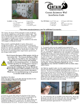
Installation Guide at the seashore
Make sure to follow below guides when installing at the
seashore.
1 Do not install the product in a place where it is directly
exposed to sea water and sea breeze.
Make sure to install the product behind a structure
(such as building) that can block see breeze.
Even when it is inevitable to install the product in
seashore, make sure that product is not directly
exposed to sea breeze by installing a protection wall.
2 Consider that the salinity particles clinging to the external
panels should be sufficiently washed out.
3 Because the residual water at the bottom of the outdoor
unit significantly promotes corrosion, make sure that the
slope does not disturb drainage.
Keep the floor level so that rain does not accumulate.
Be careful not to block the drain hole due to foreign
substance.
4 When product is installed in seashore, periodically clean it
with water to remove attached salinity.
5 Make sure to install the product in a place that provides
smooth water drainage. Especially, ensure that the base
part has good drainage.
6 If the product is damaged during the installation or
maintenance, make sure to repair it.
7 Check the condition of the product periodically.
Check the installation site every 3 months and
perform anti-corrosion treatment such as R-Pro
supplied by SAMSUNG (Code : MOK-220SA) or
commercial water repellent grease and wax, etc.,
based on the product condition.
When the product is to be shut down for a long
period of time, such as off-peak hours, take
appropriate measures like covering the product.
8 If the product installed within 500m of seashore, special
anti-corrosion treatment is required.
Please contact your local SAMSUNG representative for
further details.
7
English
Installation
Sea breeze
Sea breeze
Sea
Sea
Outdoor
unit
Outdoor
unit
Outdoor
unit
Sea breeze
Protection wall
Sea
Outdoor
unit
Outdoor unit
Protection wall should be constructed with a solid
material that can block the sea breeze and the height
and width of the wall should be 1.5 times larger than
the size of the outdoor unit. (You must secure more
than 700 mm of space between the protection wall and
the outdoor unit for air circulation.)
Minimum clearances for the outdoor unit
Legends:
Wall
Minimum clearance in mm
600
300
Air flow direction
Top view Side view
Examples for installing one outdoor unit:
Unit: mm
300
1500
300
150 600
2000
1500
500
300
1500 300
8
Preparation
English
Installation
Examples for installing multiple outdoor units:
Unit: mm
1500 600 3000 3000 200
600
600
1500 300
1500
300
300 600 600 600
500
300
300
500
Step 1.3 Unpacking
Upon receipt, inspect the product to verify that it has not been
damaged during transport. If the product appears damaged,
do not install it and immediately report the damage to your
local Samsung distributor.
Packing material must be disposed of in accordance with local
regulations.
Unpacking the indoor unit
At the selected indoor unit location:
1 Open the indoor unit package.
2 Remove the left and right cushions.
3 Carefully remove the unit from the package.
4 Place the unit on a flat surface where it will be protected
from possible damage.
Unpacking the outdoor unit
At the selected outdoor unit location:
1 Remove the package.
2 Remove the top cushion.
3 Carefully remove the unit from the bottom cushion.
4 Place the unit on a flat surface where it will be protected
from possible damage.
9
English
Installation
Step 1.4 Preparing materials and tools
Materials in the indoor unit package
Make sure that the indoor unit package contains the following
materials:
Mounting bracket (1)
**09/10/12/13*******
Mounting bracket (1)
**18/24*******
Remote control (1)
Remote control battery (2)
General information (1) Quick guide (1)
Installation manual (1)
Holder remocon (1)
Extra M4 x 12 tapping
screw (2)
Materials in the outdoor unit package
Make sure that the outdoor unit package contains the
following materials:
Rubber foot (4) Drain plug (1)
Optional accessories
Insulated assembly pipe,
Ø 6.35 mm (1)
Insulated assembly pipe,
Ø 9.52 mm (1)
**09/10/12/13*******
Insulated assembly pipe,
Ø 12.70 mm (1)
**18*******
Insulated assembly pipe,
Ø 15.88 mm (1)
**24*******
Pipe clamp B (3) Pipe clamp A (3)
Drain Hose, 2 m long (1) Foam Insulation (1)
Vinyl tape (2)
PE T3 foam tube
insulation (1)
Putty 100 g (1) M4 x 25 tapped screw (6)
Cement nail (6)
4-wire Assembly Cable (1)
**12TSHY***
3-wire Power Cable (1)
**12TSHZ***
**12TSEA***
**09/10/13/18/24*******
3-wire Assembly Cable (1)
**12TSHZ***
**12TSEA***
**09/10/13/18/24*******
2-wire Assembly Cable (1)
**12TSHZ***
**12TSEA***
**09/10/13/18/24*******
10
Preparation
English
Installation
NOTE
A flare nut is attached to the end of each refrigerant
pipe coming from the evaporator. Use these flare nuts
when connecting the pipes.
Materials supplied by the installer
Make sure you have all other materials required for the
selected installation method and location.
IMPORTANT
No mounting hardware, tubing, cables, and other
materials listed below are included with the appliance.
The required materials will vary, but may include the following:
1.8 m electrical whip for connecting the power from the
installed disconnect switch to the outdoor unit
UV-resistant vinyl line set tape for the exposed line set
Lines-set cover and fittings, if used
Miscellaneous pipe hangers
Miscellaneous screws and anchors for hanging pipe
hangers, the line-set cover, the indoor unit mounting
bracket, and so on.
Electrical ring connectors for connecting all power and
communication wiring
Electrical tape
Refrigerant R-410A if additional refrigerant is required
due to line-set length
Closed cell foam tape insulation (roll)
Outdoor unit risers or L-brackets for wall installation
Silicone caulking for sealing the wall penetration
Rags
Tools
Make sure you have the required tools available.
General tools
Vacuum pump
(Backward flowing prevention)
Manifold gauge
Stud finder
Torque wrench
Pipe cutter
Reamer
Pipe bender
Spirit level
Screwdriver
Spanner
Drill
L-wrench
Measuring tape
Tools for test operation
Thermometer
Resistance meter
Electroscope
11
English
Installation
Step 2.1 Attaching the mounting bracket
to the wall
1 Hold the mounting bracket against the wall at the
selected installation position (Step 1.2 on page 5),
making sure that the screw holes align with the center of
the studs in the wall. If the screw locations do not align
with the studs, use wall anchors.
CAUTION
The recommended best practice is to attach the
mounting bracket directly to the studs in the wall. If
you did not find a suitable location with studs (in Step
1.2 on page 5), or if the wall is concrete, you must
use wall anchors of a suitable type and weight capacity,
and install them according to the manufacturer’s
instructions. Failure to do so may cause the material
surrounding the joints to crumble over time and the
screws to be loosened and stripped. This may result
in the unit falling from the wall, which could cause
physical injury or equipment damage.
2 Using a level, make sure that the mounting bracket is
level, then mark the location of the screw holes on the
wall.
3 If using wall anchors, install them at the screw hole
positions, following the manufacturer’s instructions.
4 Using six field-supplied mounting screws and anchors (if
applicable), attach the bracket to the wall.
Screw Location x 4ea
Level
Step 2.2 Drilling the wall penetration
1 Determine the position of the hole through which the
piping bundle (consisting of power and communication
cables, refrigerant pipes, and the drain hose) will pass.
Consider the following:
The hole inner diameter must be 65 mm.
The recommended hole location is behind the unit
so that the hole and the piping bundle will not
be visible in the room. The minimum distances
between the hole and the mounting bracket are:
a
b c
Possible positions for hole behind unit
Center of indoor unit (B)
Center of indoor unit (A)
Model a b c
**09*******
**10*******
**12*******
**13*******
A 165 305 416
**18*******
**24*******
A 150 305 650.5
If the hole cannot be positioned behind the unit,
find a position as close to the unit as possible. The
piping bundle that exits the unit and extends to the
hole will need to be attached to the wall and will be
visible inside the room.
In relation to the bracket shown above, the unit
is shipped with the drain hose connection on the
right, the drain hose exits the unit on the left, and
the refrigerant pipes are bent to exit on the left.
Thus, positioning the hole to the left requires the
least effort. If you position the hole to the right
or below the unit, you will need to move the drain
hose connection to the left and bend the pipes so
that the hose and pipes exit to the right or bottom.
See the figure in step 3 on page 12.
Indoor Unit Installation
12
Indoor Unit Installation
English
Installation
2 Use a standard 65 mm hole saw to drill one hole at the
selected location, at a 15° downward angle so that the
drain hose will drain properly.
Drain hose
Wall
Indoor unit
3 Based on the hole location, determine where the piping
bundle (drain hose, refrigerant pipes, and cables) will exit
the unit.
Left
Right
bottom
Rear right or left
<Front view>
<Side view>
NOTE
The left, right, or bottom exit will only be used if the
hole is not positioned behind the unit.
Step 2.3 Connecting the refrigerant pipes
Connect indoor and outdoor units with field-supplied copper
pipes by means of flare connections. Use insulated seamless
refrigeration grade pipe only, (Cu DHP type according to
ISO1337), degreased and deoxidized, suitable for operating
pressures of at least 4200 kPa and for burst pressure of at
least 20700 kPa. Under no circumstances must sanitary type
copper pipe be used.
IMPORTANT
When installing the unit, always connect the
refrigerant pipes first, followed by the electrical cables.
For disassembly, always disassemble the electric cables
before the refrigerant pipes.
Two short refrigerant pipes are already attached to the air
conditioner:
The smaller-diameter pipe is for the high-pressure,
two-phase refrigerant.
The larger-diameter pipe is for the low-pressure
refrigerant vapor.
Drain hose
Refrigerant
pipes
(assembly pipe)
Connection hose
In Step 2.2, step 3 you determined the exit position for the
piping bundle. The unit has three knockouts available for the
left, right, and bottom exits. When the bundle exits directly
from the rear, none of the knockouts are used.
1 If the pipes will exit directly from the rear, skip to step 3.
Otherwise, cut out the appropriate knockout piece (left,
right, or bottom).
2 Use a razor knife to clean the cut edges (flashing).
3 The left exit is the only position that does not require
bending the pipes. For other positions, bend the pipes so
that they will exit in the selected exit position.
The bending radius should be greater than 100 mm.
Bend the smaller pipe gradually to prevent kinking.
The larger pipe has a preinstalled spring bender to
prevent kinking.
Make sure that the pipes do not protrude from the
back of the unit in a way that will make it difficult to
attach the unit to the mounting bracket.
For right and bottom exits, pull the pipes out through
the selected knockout opening. For left exits, the
piping connections will be made in the service space
behind the indoor unit (under the cover panel).
NOTE
If you are using the right rear exit, the pipes should
be long enough to extend through the wall without
needing to connect the line set first. It may be easier
to connect the line set outside of the building, after
you have bundled the pipes and cables and passed the
bundle through the wall. In this case, do not connect
the line set now. Instead, complete Step 2.4 through
Step 2.7, then go outside and connect the line set as
described below.
13
English
Installation
4 Slowly remove the protective caps on the refrigerant pipe
connections to relieve the nitrogen holding charge.
5 Connect the line set to each pipe.
Indoor outlet pipe Connecting pipe
Flare nut
6 Hand-tighten the flare nuts to make sure that they do not
become stripped.
Liquid service port
<High pressure>
Gas service port
<Low pressure>
7 Torque the flare connections to the following values:
(Unit: mm)
Outer diameter Torque (N·m)
ø 6.35 14–18
ø 9.52 34–42
ø 12.70 49–61
ø 15.88 68–82
CAUTION
Tighten the flare nuts only to the specified torque. If
a flare nut is overtightened, the flare face may crack,
causing refrigerant leakage.
8 Do not box in or cover the pipe connections. Make sure
that the connections are accessible for testing later in the
installation process and for future servicing.
9 Tape over the end of the pipes so that debris will not enter
the piping when it is passed through the wall. The pipes
will be insulated later in the installation process.
Step 2.4 Connecting the power and
communication cables
WARNING
Do not modify the power cable in any way. Doing so may
cause electric shock or fire due to poor connection, poor
insulation, or current limit override. Make sure to comply
with the technical standards of electrical installations
and the wiring regulations in the local area.
This appliance must be properly grounded. Do not
ground the appliance to a gas pipe, plastic water pipe,
or telephone line. Failure to comply may result in
electric shock, fire, and explosion.
1 Connect each wire to its corresponding terminal number.
Model **12TSHY***
Power cable
(Indoorunit)
3G X 1.0 mm²,
H05VV-F
Indoor-to-outdoor
power cable
4G X 1.5 mm²,
H07RN-F
Type GL
16A
Model
**09*******
**10*******
**12TSHZ***
**12TSEA***
**13*******
**18*******
**24*******
Power cable
(Outdoor unit)
3G X 2.5 mm²,
H07RN-F
3G X 2.5 mm²,
H07RN-F
Outdoor-to-indoor
power cable
3G X 1.0 mm²,
H07RN-F
3G X 1.0 mm²,
H07RN-F
Communication
cable
2 X 0.75 mm²,
H05RN-F
2 X 0.75 mm²,
H05RN-F
Type GL
16A 20A
14
Indoor Unit Installation
English
Installation
Control box
Before
connecting
Correct
Upside
down
Damaged Non-circular
After
connecting
Correct
(Front
view)
Correct
(Side view)
Upside
down
Non-fitted
<Circular terminal>
CAUTION
Connect the wires firmly so that wires cannot be pulled
out. Loose wires can cause the connection to overheat.
Each circular terminal must match the size of its
corresponding screw in the terminal block.
CAUTION
For the terminal block wiring, use a wire with a
ring terminal socket only. Regular wires without a
ring terminal socket may become a hazard as the
connections may loosen during operation.
2 Tighten the terminal block screw.
N 1 2
1(L) 2(N) F1 F2
3 In Step 2.2, step 3 you determined the exit position for the
piping bundle. If using the left, right, or bottom exits, pass
the cables through the selected knockout.
NOTE
Power supply cords of parts of appliances for outdoor
use shall not be lighter than polychloroprene sheathed
flexible cord. (Code designation IEC: 60245 IEC66/
CENELEC: H07RN-F, IEC: 60245 IEC57 CENELEC:
H05RN-F, IEC: 60227 IEC53: H05VV-F)
Power & Communication cable shall not exceed 30 m.
**12TSHY*** **12TSHZ***
**12TSEA***
**09/10/13/18/24*******
15
English
Installation
Step 2.5 Optional: Extending the power
cable
1 Prepare the following tools.
Tools Spec Shape
Crimping pliers MH-14
Connection sleeve
(mm)
20xØ6.5 (HxOD)
Insulation tape Width 19 mm
Contraction tube
(mm)
70xØ8.0 (LxOD)
2 As shown in the figure, peel off the shields from the
rubber and wire of the power cable.
Peel off 20 mm of cable shields from the pre-
installed tube.
CAUTION
For information about the power cable specifications
for indoor and outdoor units, refer to the installation
manual.
After peeling off cable wires from the pre-installed
tube, insert a contraction tube.
If cable wires are connected without using connecting
sleeves, their contact area becomes reduced, or
corrosion develops on the outer surfaces of the wires
(copper wires) over a long time. This may cause an
increase of resistance (reduction of passing current)
and consequently may result in a fire.
20 20 20
60
120
180
Power cable
202020
60
120
180
Pre-installed
tube for the
power cable
(Unit: mm)
3 Insert both sides of core wire of the power cable into the
connection sleeve.
Method 1: Push the core wire into the sleeve from
both sides.
Method 2: Twist the wire cores together and push it
into the sleeve.
Method 1 Method 2
Connection sleeve
Connection sleeve
4 Using a crimping tool, compress the two points and flip
it over and compress another two points in the same
location.
The compression dimension should be 8.0.
Compression
dimension
After compressing it, pull both sides of the wire to
make sure it is firmly pressed.
Compress it 4 times
5 mm
Method 1 Method 2
Compress it 4 times
5 mm
5 Wrap it with the insulation tape twice or more and
position your contraction tube in the middle of the
insulation tape.
40 mm
Insulation tape
Method 1
35 mm
Insulation tape
Method 2
16
Indoor Unit Installation
English
Installation
6 Apply heat to the contraction tube to contract it.
Contraction tube
Method 1
Contraction tube
Method 2
7 After tube contraction work is completed, wrap it with the
insulation tape to finish.
Three or more layers of insulation are required.
Insulation tape
Method 1
Insulation tape
Method 2
CAUTION
Make sure that the connection parts are not exposed
to outside.
Be sure to use insulation tape and a contraction tube
made of approved reinforced insulating materials
that have the same level of withstand voltage with
the power cable. (Comply with the local regulations on
extensions.)
WARNING
In case of extending the electric wire, please DO NOT use
a round-shaped Pressing socket.
Incomplete wire connections can cause electric
shock or a fire.
Step 2.6 Connecting the drain hose
1 In Step 2.2, step 3 you determined the exit position for the
piping bundle. If using the right, bottom, or right rear exit,
change the drain hose connection from the right to the
left so that the drain hose will lie along the inside of the
unit and exit to the right.
Drain pan outlet
Rubber cap
CAUTION
Be careful not to puncture the plug with the
screwdriver when installing it.
2 If using the left, right, or bottom exit, pass the drain hose
through the selected knockout.
Drain hose
Refrigerant pipes
(assembly pipe)
Connection hose
3 Connect a 15.88 mm ID extension drain hose to the main
drain hose.
17
English
Installation
CAUTION
If the diameter of the connection hose is smaller than
the product’s drain hose, leakage may occur.
(A) (B)
40~45 mm
Drain hose (A)
Drain hose
Vinyl tape
Extension drain hose (B)
Extension drain hose
20 mm or more
Foam insulation
40~45mm
4 Do not box in or cover the drain hose connection. It must
be accessible for testing later in the installation process
and for future servicing.
5 If the drain hose is routed inside the room, insulate the
hose so that dripping condensation does not damage the
furniture or floors.
Step 2.7 Taping the pipes, cables, and
drain hose
1 Wrap foam insulation around the refrigerant pipes, up
to the connection points. The connections must remain
accessible for testing later in the installation process.
Either leave slits in the insulation or do not cover the
connections.
Insulation
Refrigerant pipes
Test parts for the
indoor unit
2 Make a piping bundle by using vinyl tape to wrap together
the refrigerant pipes, power cable, communication cable,
and drain hose, up to the connection points. Connection
points must remain accessible for testing later in the
installation process.
Mounting bracket
Vinyl tape
Drain hose
Power and communication
cables (assembly cable)
Refrigerant pipes
(assembly pipe)
18
Outdoor Unit Installation
English
Installation
Step 3.1 Mounting the outdoor unit
To promote proper condensate draining, the recommended
installation of the outdoor unit is elevated above the ground
on a mounting bracket attached to a concrete pad.
In areas where snowfall occurs, the unit must be mounted
above the snow line to allow for proper heating. Snow cannot
be allowed to collect on top of the unit. For promoting natural
drainage in a heavy snow fall area:
Make space more 80 mm between the bottom of the
outdoor unit and the ground for installation. (Ensure
that the drained water runs off correctly and safely.)
Allow enough separation distance between the product
and the ground.
80 mm
Estimated
snow fall
Snow-proof
hood
Ground
On the ground
1 Place the outdoor unit in the selected installation location
(Step 1.1 on page 4), ensuring proper clearances and with
the arrow on top of the unit pointing away from the wall.
2 Clip the rubber feet to the tabs to minimize sound and
vibration to the structure.
X
Rubber leg
Y
(Unit: mm)
Model X Y
**09/12TSHZ*** 436 265
**12TSEA***
**12TSHY***
**10/13TSFC***
507 292
**18TSHZ*** 602 310
**18TSEA***
**18TSHZ***
**18TSHY***
**18TSF****
**24*******
660 340
3 Level the unit, then use anchor bolts to secure it at the
four mounting points.
4 For installations in locations that require seismic or
hurricane tie downs, comply with local codes.
5 If the selected location is exposed to strong winds, install
a protective fence around the unit so that the fan can
operate correctly.
On a wall
WARNING
The unit must be properly secured to the wall. If the
unit falls, it may result in crushing, electric shock, fire,
or explosion that could cause death, severe personal
injury, or property damage.
1 At the selected installation location (Step 1.1 on page
4), attach the L-bracket to the wall as follows:
Install the bracket as close to the wall as possible.
Insert rubber isolators between the bracket and
the wall to minimize sound and vibration to the
structure. Do not fully compress the isolators.
Soft rubber designed to cut off vibration from
rack to wall (not supplied with product)
Soft rubber designed to cut off residual vibration from
outdoor unit to rack (not supplied with product)
Make sure that the bracket is level.
Use suitable bolts/washers and lock washers.
2 Place the outdoor unit on the bracket, ensuring proper
clearances and with the arrow on top of the unit pointing
away from the wall.
3 Clip the rubber feet to the tabs to minimize sound and
vibration to the structure.
4 Level the unit, then use anchor bolts to secure it at the
four mounting points.
5 For installations in locations that require seismic or
hurricane tie downs, comply with local codes.
Outdoor Unit Installation
19
English
Installation
Step 3.2 Connecting the cables and the
pipes
1 Route the piping bundle to the outdoor unit.
2 Use piping clamps to fasten the piping bundle to the
foundation or wall.
3 Cut the refrigerant pipes to the length needed to reach
the pipe connections (located behind the cover panel; see
the figure in step 7).
Pipe cutter
Pipe
Oblique Rough Burr90°
4 Remove any burrs, positioning the pipe face down to
make sure that the burrs do not get into the pipe.
5 Assemble the flare connections on the cut pipe ends.
Pipe
Flare
R 0.4 to 0.8
90°±2°
45°±2°
L
D
D
A
(Unit: mm)
Outer diameter
(D)
Depth (A) Flare dimension (L)
ø 6.35 1.3 8.7–9.1
ø 9.52 1.8 12.8–13.2
ø 12.70 2.0 16.2–16.6
ø 15.88 2.2 19.3–19.7
6 Remove the cover panel on the unit.
7 Remove the service valve caps.
20
Outdoor Unit Installation
English
Installation
8 Connect the pipes to the service valve with the flare nuts.
Hand-tighten the nuts to prevent stripping.
9 Torque the flare connections to the values in Step 2.3, step
7 on page 13.
10 Connect the power cables and secure with a cable clamp.
F1 F2
L N
Outdoor-to-indoor power cable
(three wires)
Communication cable
(two wires)
Power cable
(three wires)
11 Connect the outdoor unit power supply cable to the
preinstalled disconnect switch.
12 Leave the cover panel off for testing later in the
installation process.
N
1 2
**12TSHY***
**12TSHZ***
**12TSEA***
**09/10/13/18/24*******
  • Page 1 1
  • Page 2 2
  • Page 3 3
  • Page 4 4
  • Page 5 5
  • Page 6 6
  • Page 7 7
  • Page 8 8
  • Page 9 9
  • Page 10 10
  • Page 11 11
  • Page 12 12
  • Page 13 13
  • Page 14 14
  • Page 15 15
  • Page 16 16
  • Page 17 17
  • Page 18 18
  • Page 19 19
  • Page 20 20
  • Page 21 21
  • Page 22 22
  • Page 23 23
  • Page 24 24
  • Page 25 25
  • Page 26 26
  • Page 27 27
  • Page 28 28

Samsung AR12TSHZRWKXRC Installation guide

Category
Split-system air conditioners
Type
Installation guide

Ask a question and I''ll find the answer in the document

Finding information in a document is now easier with AI