Onan emerald plus series Installation guide
- Category
- Power generators
- Type
- Installation guide

Caution: This document contains mixed page sizes (8.5 x 11 or 11 x
17), which may affect printing. Please adjust your printer settings
according to the size of each page you wish to print.

Printed U.S.A.
965−0628
10−96
Emerald Plus Series
BGE, NHE

The engine exhaust from this product
contains chemicals known to the State
of California to cause cancer, birth
defects or other reproductive harm.
!!

Table of Contents
i
SECTION TITLE PAGE
SAFETY PRECAUTIONS ii. . . . . . . . . . . . . . . . . . . . . . . . . . . . . . . . . . . . . . . . . . .
1 INTRODUCTION 1-1. . . . . . . . . . . . . . . . . . . . . . . . . . . . . . . . . . . . . . . . . . . . . . . . . .
About This Manual 1-1. . . . . . . . . . . . . . . . . . . . . . . . . . . . . . . . . . . . . . . . . . . . . . .
Installation Codes and Standards for Safety 1-1. . . . . . . . . . . . . . . . . . . . . . . . .
Genset Outline Drawings 1-1. . . . . . . . . . . . . . . . . . . . . . . . . . . . . . . . . . . . . . . . .
2 SPECIFICATIONS 2-1. . . . . . . . . . . . . . . . . . . . . . . . . . . . . . . . . . . . . . . . . . . . . . . . .
3 Location and Mounting 3-1. . . . . . . . . . . . . . . . . . . . . . . . . . . . . . . . . . . . . . . . . . .
General 3-1. . . . . . . . . . . . . . . . . . . . . . . . . . . . . . . . . . . . . . . . . . . . . . . . . . . . . . . .
Compartment Mount 3-1. . . . . . . . . . . . . . . . . . . . . . . . . . . . . . . . . . . . . . . . . . . . .
Under-Floor Mount 3-2. . . . . . . . . . . . . . . . . . . . . . . . . . . . . . . . . . . . . . . . . . . . . .
4 VENTILATION AND ACOUSTICS 4-1. . . . . . . . . . . . . . . . . . . . . . . . . . . . . . . . . . .
Ventilation 4-1. . . . . . . . . . . . . . . . . . . . . . . . . . . . . . . . . . . . . . . . . . . . . . . . . . . . . .
Acoustics 4-3. . . . . . . . . . . . . . . . . . . . . . . . . . . . . . . . . . . . . . . . . . . . . . . . . . . . . . .
5 EXHAUST SYSTEM 5-1. . . . . . . . . . . . . . . . . . . . . . . . . . . . . . . . . . . . . . . . . . . . . . .
General 5-1. . . . . . . . . . . . . . . . . . . . . . . . . . . . . . . . . . . . . . . . . . . . . . . . . . . . . . . .
Muffler Recommendations 5-1. . . . . . . . . . . . . . . . . . . . . . . . . . . . . . . . . . . . . . . .
Exhaust Installation Guidelines 5-1. . . . . . . . . . . . . . . . . . . . . . . . . . . . . . . . . . . .
Tailpipe Recommendations 5-3. . . . . . . . . . . . . . . . . . . . . . . . . . . . . . . . . . . . . . .
6 FUEL SYSTEM 6-1. . . . . . . . . . . . . . . . . . . . . . . . . . . . . . . . . . . . . . . . . . . . . . . . . . .
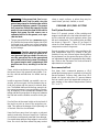
General 6-1. . . . . . . . . . . . . . . . . . . . . . . . . . . . . . . . . . . . . . . . . . . . . . . . . . . . . . . .
Gasoline Fuel System 6-1. . . . . . . . . . . . . . . . . . . . . . . . . . . . . . . . . . . . . . . . . . . .
Propane (LPG) Fuel System 6-2. . . . . . . . . . . . . . . . . . . . . . . . . . . . . . . . . . . . . .
Propane (LP-Vapor) Fuel System 6-5. . . . . . . . . . . . . . . . . . . . . . . . . . . . . . . . . .
7 ELECTRICAL CONNECTIONS 7-1. . . . . . . . . . . . . . . . . . . . . . . . . . . . . . . . . . . . .
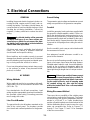
General 7-1. . . . . . . . . . . . . . . . . . . . . . . . . . . . . . . . . . . . . . . . . . . . . . . . . . . . . . . .
AC Wiring 7-1. . . . . . . . . . . . . . . . . . . . . . . . . . . . . . . . . . . . . . . . . . . . . . . . . . . . . .
DC Wiring 7-5. . . . . . . . . . . . . . . . . . . . . . . . . . . . . . . . . . . . . . . . . . . . . . . . . . . . . .
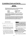
8 INSTALLATION CHECKS AND START-UP 8-1. . . . . . . . . . . . . . . . . . . . . . . . . . .
Pre-Start Checks 8-1. . . . . . . . . . . . . . . . . . . . . . . . . . . . . . . . . . . . . . . . . . . . . . . .
Initial Starting and Checks 8-1. . . . . . . . . . . . . . . . . . . . . . . . . . . . . . . . . . . . . . . .
Installation Review 8-3. . . . . . . . . . . . . . . . . . . . . . . . . . . . . . . . . . . . . . . . . . . . . . .
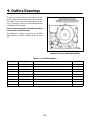
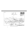
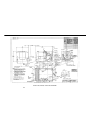
9 OUTLINE DRAWINGS 9-1. . . . . . . . . . . . . . . . . . . . . . . . . . . . . . . . . . . . . . . . . . . . .

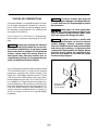
Safety Precautions
ii
Thoroughly read the INSTALLATION MANUAL
before installing the genset. Safe operation and
top performance can be obtained only with prop-
er genset installation.
The following symbols in this Manual alert you to po-
tential hazards to the operator, service person and
equipment.
Alerts you to an immediate hazard
which will result in severe personal injury or
death.
WARNING
Alerts you to a hazard or unsafe prac-
tice which can result in severe personal injury or
death.
CAUTION
Alerts you to a hazard or unsafe prac-
tice which can result in personal injury or equip-
ment damage.
Electricity, fuel, exhaust, moving parts and batteries
present hazards which can result in severe personal
injury or death.
GENERAL PRECAUTIONS
• Keep ABC fire extinguishers handy.
• Make sure all fasteners are secure and torqued
properly.
• Keep the genset and its compartment clean. Ex-
cess oil and oily rags can catch fire. Dirt and gear
stowed in the compartment can restrict cooling
air.
• Before working on the genset, disconnect the
negative (- ) battery cable at the battery to pre-
vent starting.
• Use caution when making adjustments while the
genset is running—hot, moving or electrically
live parts can cause severe personal injury or
death.
• Used engine oil has been identified by some
state and federal agencies as causing cancer or
reproductive toxicity. Do not ingest, inhale, or
contact used oil or its vapors.
• Benzene and lead in some gasolines have been
identified by some state and federal agencies as
causing cancer or reproductive toxicity. Do not
ingest, inhale or contact gasoline or its vapors.
• Do not work on the genset when mentally or
physically fatigued or after consuming alcohol or
drugs.
• Carefully follow all applicable local, state and
federal codes.
GENERATOR VOLTAGE IS DEADLY!
• Generator output connections must be made by
a qualified electrician in accordance with appli-
cable codes.
• The genset must not be connected to the public
utility or any other source of electrical power.
Connection could lead to electrocution of utility
workers, damage to equipment and fire. An ap-
proved switching device must be used to prevent
interconnections.
• Use caution when working on live electrical
equipment. Remove jewelry, make sure clothing
and shoes are dry and stand on a dry wooden
platform on the ground or floor.
FUEL IS FLAMMABLE AND EXPLOSIVE
• Keep flames, cigarettes, sparks, pilot lights,
electrical arc-producing equipment and switches
and all other sources of ignition well away from
areas where fuel fumes are present and areas
sharing ventilation.
• Fuel lines must be secured, free of leaks and
separated or shielded from electrical wiring.
• Use approved non-conductive flexible fuel hose
for fuel connections at the genset.
ENGINE EXHAUST IS DEADLY!
• Learn the symptoms of carbon monoxide poi-
soning in this Manual.
• Never sleep in the vehicle while the genset is
running unless the vehicle has a working carbon
monoxide detector.
• The exhaust system must be installed in accor-
dance with the genset Installation Manual.
• Do not use engine cooling air to heat the vehicle
interior.
• Make sure there is ample fresh air when operat-
ing the genset in a confined area.

iii
MOVING PARTS CAN CAUSE SEVERE
PERSONAL INJURY OR DEATH
• Do not wear loose clothing or jewelry near mov-
ing parts such as PTO shafts, fans, belts and pul-
leys.
• Keep hands away from moving parts.
• Keep guards in place over fans, belts, pulleys,
etc.
BATTERY GAS IS EXPLOSIVE
• Wear safety glasses and do not smoke while ser-
vicing batteries.
• When disconnecting or reconnecting battery
cables, always disconnect the negative (- ) bat-
tery cable first and reconnect it last to reduce arc-
ing.
MBL-1

1. Introduction
1-1
ABOUT THIS MANUAL
This manual is a guide for the installation of the gen-
erator set (genset) models listed on the front cover.
Proper installation is essential for top performance.
Read through this manual before starting the instal-
lation.
This manual addresses the following aspects of the
installation:
• Location and Mounting
• Exhaust Connections
• Fuel Connections
• Electrical Connections (AC power output, con-
trol and battery)
• Startup
WARNING
Improper installation can result in
severe personal injury, death and equipment
damage. The installer must be qualified to per-
form the installation of electrical and mechani-
cal equipment.
See the Operator’s Manual for operation and main-
tenance and the Service Manual for service.
NOTE: Manuals are updated from time to time to re-
flect changes in the equipment and its specifica-
tions. For this reason, only the copy of the installa-
tion manual supplied with the genset should be used
as a guide for the installation.
INSTALLATION CODES AND STANDARDS
FOR SAFETY
The builder of the RV bears sole responsibility for
the selection of the appropriate genset, for its prop-
er installation and for obtaining approvals from the
authorities (if any) having jurisdiction over the
installation. These sets meet the basic require-
ments of the Standard for Safety for Engine Gener-
ator Sets for Recreational Vehicles, ANSI/RVIA
EGS-1. They are suitable for installation in accor-
dance with:
• The National Electrical Code, NFPA No. 70, Ar-
ticle 551
• The Standard on Recreational Vehicles, NFPA
No. 501C
Federal, State and local codes, such as the Califor-
nia Administrative Code—Title 25 (RV installation),
might also be applicable. Installation codes and rec-
ommendations can change from time-to-time and
are different in different countries, states and mu-
nicipalities. It is recommended that the standards in
Table 1-1 be obtained for reference.
TABLE 1-1. REFERENCE CODES AND
STANDARDS
NFPA Nos.
70 & 501C
National Fire Protection Association
470 Atlantic Avenue, Boston, MA 02210
ANSI/RVIA-EGS-1
Recreational Vehicle Industry Association
14650 Lee Road, Chantily, VA 22021
California Adminis-
trative Code—Title
25, Chapter 3
State of California Documents Section
P.O. Box 1015, North Highlands, CA 95660
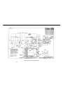
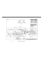
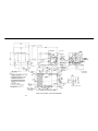
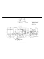
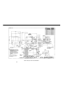
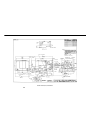
GENSET OUTLINE DRAWINGS
See
Outline Drawings
for the dimensions of the
genset and the locations of the mounting bolt holes,
inlet and outlet air openings, oil drain plug, mainte-
nance access door and connection points (fuel, bat-
tery, remote control, AC, exhaust).
See your Onan dealer for large-scale drawings and
a floor template to locate the opening cutouts.

1-2
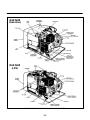
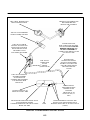
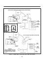
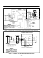
BGE/NHE
(LPG)
BGE/NHE
(Gasoline)
REMOTE START CABLE
CONNECTION
REMOTE START CABLE
CONNECTION
FIGURE 1-1. TYPICAL EMERALD PLUS GENERATOR SETS

2. Specifications
2-1
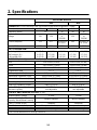
GASOLINE MODELS
BGE NHE
GENERATOR: 4-Pole Revolving Field, Self-Excited, Electronically Regulated, 1-Phase
Power (watts) 4000 5000 4000 6500 5000
Frequency (Hertz) 60 50 60 50
Voltage 120 120
110/220
or
120/240
120
110/220
or
120/240
Current (amperes) 33.3 41.7
36.4/18.2 or
33.3/16.7
54.2
45.5/22.7 or
41.7/20.8
Speed (RPM) 1800 1800 1500 1800 1500
FUEL CONSUMPTION:
No load gph (l/h)
Half load gph (l/h)
Full load gph (l/h)
0.4 (1.5)
0.6 (2.3)
0.8 (3.0)
0.4 (1.5)
0.7 (2.6)
1.0 (3.8)
0.3 (1.1)
0.5 (1.9)
0.8 (3.0)
0.4 (1.5)
0.7 (2.6)
1.3 (4.9)
0.4 (1.5)
0.7 (2.6)
1.0 (3.8)
ENGINE: 2-Cylinder Opposed, 4-Cycle, Spark-Ignited, Side-Valve, Air Cooled
Bore 3.250 inches (83 mm) 3.563 inches (90 mm)
Stroke 2.875 inches (73 mm) 3.000 inches (76 mm)
Displacement 48 inches
3
(782 cc) 60 inches
3
(980 cc)
Compression Ratio 7.0 : 1 7.0 : 1
Oil Capacity (with filter)* 3.5 quarts (3.3 l) 3.5 quarts (3.3 l)
Intake Valve Clearance (Cold) 0.005 inches (0.13 mm) 0.005 inches (0.13 mm)
Exhaust Valve Clearance (Cold) 0.013 inches (0.33 mm) 0.013 inches (0.33 mm)
Spark Plug Gap 0.025 inches (0.64 mm) 0.025 inches (0.64 mm)
Spark Plug Tightening Torque 8 lbs-ft (10 N-m) 8 lbs-ft (10 N-m)
Ignition Timing
(electronic ignition)
12° BTDC,
non-adjustable
12° BTDC,
non-adjustable
CONTROL AND CRANKING SYSTEM: 12 VDC
Nominal Battery Voltage 12 volts 12 volts
Minimum Battery Cold Cranking
Capacity: Above/Below Freezing
360/450 amperes 360/450 amperes
Fuse F1 (control circuit) 5 amperes 5 amperes
Fuse F2 (autochoke/fuel pump) 10 amperes mini-bayonet 10 amperes mini-bayonet
WEIGHT: 216 lb (98 kg) 230 lb (105 kg)
* -See
Periodic Maintenance
for oil filling instructions.

2-2
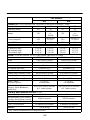
LPG MODELS
BGE NHE
GENERATOR: 4-Pole Revolving Field, Self-Excited, Electronically Regulated, 1-Phase
Power (watts) 4000 4000 6300 5000
Frequency (Hertz) 60 50 60 50
Voltage 120
110/220
or
120/240
120
110/220
or
120/240
Current (amperes) 33.3
36.4/18.2 or
33.3/16.7
52.5
45.5/22.7 or
41.7/20.8
Speed (RPM) 1800 1500 1800 1500
FUEL CONSUMPTION:
No load lbs/h (kg/h)
Half load lbs/h (kg/h
Full load lbs/h (kg/h
1.8 (0.8)
2.6 (1.2)
4.0 (1.8)
1.5 (0.7)
2.6 (1.2)
4.0 (1.8)
2.2 (1.0)
3.8 (1.7)
6.6 (3.0)
2.0 (0.9)
3.5 (1.6)
5.1 (2.3)
ENGINE: 2-Cylinder Opposed, 4-Cycle, Spark-Ignited, Side-Valve, Air Cooled
Bore 3.250 inches (83 mm) 3.563 inches (90 mm)
Stroke 2.875 inches (73 mm) 3.000 inches (76 mm)
Displacement 48 inches
3
(782 cc) 60 inches
3
(980 cc)
Compression Ratio 7.0 : 1 7.0 : 1
Oil Capacity (with filter)* 3.5 quarts (3.3 l) 3.5 quarts (3.3 l)
Intake Valve Clearance (Cold) 0.005 inches (0.13 mm) 0.005 inches (0.13 mm)
Exhaust Valve Clearance (Cold) 0.013 inches (0.33 mm) 0.013 inches (0.33 mm)
Spark Plug Gap 0.025 inches (0.64 mm) 0.025 inches (0.64 mm)
Spark Plug Tightening Torque 8 lbs-ft (10 N-m) 8 lbs-ft (10 N-m)
Ignition Timing
(electronic ignition)
12° BTDC,
non-adjustable
12° BTDC,
non-adjustable
LPG Vapor Supply Pressure
(Range)—Vapor-Withdrawal
Models Only
9 to 13 inch (229 to 330 mm)
W.C. (water column)
9 to 13 inch (229 to 330 mm)
W.C. (water column)
CONTROL AND CRANKING SYSTEM: 12 VDC
Nominal Battery Voltage 12 volts 12 volts
Minimum Battery Cold Cranking
Capacity: Above/Below Freezing
360/450 amperes 360/450 amperes
Fuse F1 (control circuit) 5 amperes 5 amperes
Fuse F2 (fuel solenoid) 10 amperes mini-bayonet 10 amperes mini-bayonet
WEIGHT: 216 lb (98 kg) 230 lb (105 kg)
* -See
Periodic Maintenance
for oil filling instructions.

3. Location and Mounting
3-1
GENERAL
Read the entire manual and housing/exhaust kit in-
structions before installing the genset. The genset
is designed for two very different types of installa-
tion: conventional compartment mount installation
and under-floor mount installation. Choose the ap-
propriate section and carefully follow the instruc-
tions given.
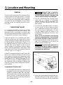
COMPARTMENT MOUNT
In a conventional installation, the genset is installed
on a framework that is part of the vehicle. This
framework must be constructed in accordance with
the safety-approved specifications contained in the
Compartment Construction
section following.
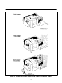
Unless the genset is to be removed from under-
neath the vehicle, plan the location for an access
opening to be large enough to permit genset remov-
al. Typical locations are illustrated in Figure 3-1. Al-
low additional clearance for easy access to the oil
fill, drain, filter, and oil dipstick, as well as the air
cleaner element, circuit breaker, governor adjust-
ments, carburetor adjustments, spark plugs, Start/
Stop switch, and DC fuse. The locations of each are
shown in Figure 1-1 on Page 1-2.
Design the compartment large enough for the gen-
set to have a minimum clearance of 0.6 inch (15
mm) between the genset and compartment walls
and ceiling (and acoustical material, if used). See
Figures 9-4, 9-5, 9-7, and 9-9 on Pages 9-4, 9-5,
9-7, and 9-9 in Section
9. Outline Drawings
for gen-
eral information when reviewing the following and
refer to the specific Outline Drawing when perform-
ing installation.
Compartment Construction
1. It is imperative that the genset compartment be
separated from the living quarters and any fuel
(gasoline or propane) supply with a vapor-tight,
fire-resistant barrier. See the appropriate fig-
ures in Section
9. Outline Drawings
(and spe-
cific Outline Drawing) for minimum clearances
and compartment size.
WARNING
EXHAUST GAS IS DEADLY.
Construct a suitable vapor barrier of ap-
proved materials between the genset and
vehicle interior to keep out exhaust gas.
2. Line the compartment with 26-gauge galva-
nized steel or a material of comparable
strength, durability, and fire resistance (see
NFPA 70, NEC and California Title 25 for com-
plete details).
3. Construct the compartment floor in a manner
so as to prevent oil, fuel, or water accumula-
tion. Compartment drainage to the outside of
the vehicle can be accomplished by 1/2-inch
(13 mm) diameter holes as shown on the
compartment floor drawings in Section
9. Out-
line Drawings
.
NOTE: Do
not
use absorbent sound proofing
material on compartment floor. The floor should
have minimal openings to reduce sound level.
4. Equip the base with an oil drain hole to the out-
side on the compartment. Do not mount the
muffler below the oil drain hole.
WARNING
Fire presents the hazard of se-
vere personal injury or death. To prevent a
fire hazard, do not position the muffler di-
rectly below the drain hole.
FIGURE 3-1. TYPICAL GENSET LOCATIONS
5. Secure the genset mounting plate to the sup-
port frame using 3/8-16 UNC, grade 5 screws.
The back two mounting holes are supplied with

3-2
weld nuts to facilitate installing screws. The
front two holes can be secured with 3/8-16
screws, lock-washers, and nuts. The front
holes are square to allow the use of 3/8-16
cage nuts, if desired. See the appropriate fig-
ure in Section
9. Outline Drawings.
CAUTION
Road vibrations can cause
component damage to the genset if the unit
mounting plate is not fastened securely to
the vehicle compartment. Use screws of
sufficient length to allow a minimum of 1
1
/
2
threads to extend through the nut for maxi-
mum holding power.
UNDER-FLOOR MOUNT
In an under-floor mount installation, the genset is
mounted in a housing below the floor and outside
the vehicle coach. This housing assembly should
be as supplied or reviewed by Onan, and must be
installed in accordance with the Installation Codes
and Safety Recommendations list in the
Introduc-
tion.
Review the following text for general applica-
tion information, and review the proper housing/ex-
haust kit instructions for further specifics regarding
under-floor mount instructions.
The vehicle construction must be able to support
the weight of the genset (see
General Specifica-
tions).
It is the vehicle manufacturer’s and the in-
staller’s responsibility to provide a structurally
sound support frame, by using tubing, angle brack-
ets, or steel reinforced plywood or other composi-
tion board. Reinforcement of plywood or other com-
position board can be accomplished with 3-inch (76
mm) or larger washers or a full metal plate.
WARNING
Design the genset support struc-
ture carefully to prevent the genset from falling
from the vehicle and possibly causing a serious
road accident.
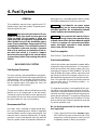
General
Genset Location.
When choosing a location for
mounting the under-floor mount genset, consider
the following not only for mounting, but for protec-
tion of the genset, as well. Figure 3-2 shows the
most common mounting areas of an RV genset in a
recreational vehicle.
FIGURE 3-2. COMMON UNDER-FLOOR MOUNTING AREAS OF GENSET

3-3
• If the genset is mounted on the curb side (loca-
tion 1 or 2), protect the generator end of the
genset from road splash and debris.
• If the genset is mounted on the driver’s side
(location 3 or 4), protect the engine end of the
genset from road splash and debris.
• Leave an area between the genset and the rec-
reational vehicle skirt for an air inlet if it is not
subjected to road splash. See Section
4.
Ven-
tilation and Acoustics
for more detailed infor-
mation.
NOTE: Air inlet openings to the genset compartment
must not allow dirt, rock, water, or slush to directly
hit the genset. Dust and salt entrance into the
compartment must be minimized. Pay special atten-
tion to protection of the generator, control, choke,
and governor areas. Baffles might be required to pro-
tect certain areas.
Access Opening.
Provide an access opening on
the side of the recreational vehicle for the genset.
Make it large enough to allow for checking or adding
oil, for adjusting the governor and carburetor, and
for access to the control panel and AC circuit break-
er. The opening should also provide access for oil
and air filter replacement so that the genset does
not have to be lowered for these procedures. See
Figure for location of genset components.
Mounting Clearances.
If the compartment door
does not open the full width of the genset and to the
bottom of the vehicle skirt, provide 2 inches (51 mm)
minimum between the tray and the skirt of the recre-
ational vehicle. This distance allows lowering the
genset without hitting the vehicle skirt. Figure 9-4 on
Page 9-4 shows basic dimensions of the under-
floor mount genset. Refer to specific Outline Draw-
ing when performing installation.
Housing Assembly
The recreational vehicle must be adapted for the
under-floor housing. The vehicle frame must sup-
port the weight of the genset. It is the vehicle
manufacturer’s responsibility to provide a structur-
ally sound frame and carriage bolts or equivalent to
attach the housing kit.
CAUTION
Failure to meet Onan review for
modifications of housing kits or for non-Onan
kit housing installations may void intent of
NCTI/CSA approval. Liability for damage or inju-
ry and warranty expenses becomes the respon-
sibility of the person making the modifications.
Use the template supplied with the housing kit so
that panels are installed square to each other. Fail-
ure to mount panels square may result in spark plug
breakage.
Review
Exhaust System
section and exhaust sys-
tem kit installation instructions and component
parts. Plan clearance for movement or removal of
exhaust components when the genset is lowered
for inspection or maintenance purposes.

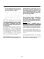
4. Ventilation and Acoustics
4-1
WARNING
EXHAUST GASES ARE DEADLY!
Never sleep in the vehicle with the genset run-
ning unless the vehicle is equipped with an op-
erating carbon monoxide detector with an audi-
ble alarm.
WARNING
Provide an adequate exhaust sys-
tem to properly expel discharged gases. In-
spect exhaust system daily for leaks per the
maintenance schedule. Check that exhaust
manifolds are secure and not warped. Do not
use exhaust gases to heat a compartment.
WARNING
Be sure the unit is well ventilated.
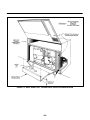
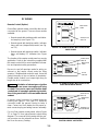
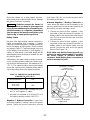
VENTILATION
The most important factors of ventilation for an RV
air-cooled genset are sufficient incoming air (for
combustion and cooling) and adequate exhausting
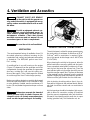
of heated air. The BGE/NHE genset uses Vacu-
Flo cooling.
A centrifugal fan in a scroll housing on the engine
(Figure 4-1) draws air from the generator end of the
compartment, through the generator (the generator
also has a cooling fan), and over the cooling sur-
faces of the engine. Then, it discharges the heated
air out through the Vacu-Flo discharge opening.
Make sure nothing obstructs or restricts discharged
airflow and that recirculation of air is minimal. A dust
or noise deflector, if added, must be a minimum of 3
inches (76 mm) below the genset and open on three
sides.
WARNING
Exhaust gas presents the hazard of
severe personal injury or death. Because dis-
charged cool air can contain some exhaust gas,
never use discharged cooling air for heating.
FIGURE 4-1. VACU-FLO
COOLING SYSTEM
The air inlet area is critical for proper genset opera-
tion and cooling. A minimum air inlet area of 85 in
2
(548 cm
2
) with no restrictions is required. Refer-
ence: the genset air discharge rate is 480 ft
3
/min
(13.6 m
3
/min).
When planning the air inlet to the genset, allow for
airflow restrictions caused by grilles and duct work.
Some expanded metal grilles provide only 60 per-
cent free air inlet area per square foot. Even the
most efficient grille only provides about 90 percent
free inlet area per square foot. The free air inlet area
of the material can be obtained from the material
supplier. Multiply the grille area times the percent of
free area of the grill to obtain the free inlet area.
Inlet air ducting should provide a direct, free, air-
flow path to the genset, with minimal bends. Materi-
als used should be smooth and non-restrictive to
airflow.
Air inlet openings should be located as high as pos-
sible to allow for convection cooling of heated air
from the genset compartment after unit shutdown.
Otherwise, hard starting might result due to vapor
locking (gasoline fuel), hot combustion air,
etc.

4-2
WARNING
Fuel and fuel leakage present the
hazard of fire or explosion, which can cause se-
vere personal injury or death. The ventilation
system should provide a constant flow of air to
expel any accumulation of fuel vapor. The gen-
set compartment must be vapor-tight to the ve-
hicle interior to keep fumes from entering the
vehicle.
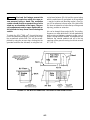
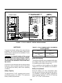
To obtain the 85 in
2
(548 cm
2
) free air inlet area,
Onan recommends bringing in cooling air through
the recreational vehicle skirt. This can be accom-
plished by using the access door, ducting into the
generator end from the side wall, or using the hori-
zontal area between RV skirt and the genset along
with the vertical area (if road splash is not a problem
—see the
Location and Mounting
section). See Fig-
ure 4-2 for reference to these areas. If the skirt of the
RV does not extend to or below the top of the genset
drip tray, provide an extension.
Air can be brought from under the RV for cooling.
However, run tests while the RV is both parked and
while moving at highway speeds to make sure of
proper cooling with this method. A temperature rise
between the outside ambient and air in the top
openings of the genset housing should not exceed
8F (4.4C).
FIGURE 4-2. AIR INLET ALTERNATIVES FOR UNDER-FLOOR MOUNT GENSET

4-3
ACOUSTICS
The Onan housing kit for the under-floor mount gen-
set contains acoustical material to minimize noise.
Additional insulation is not necessary. If, however,
you are constructing your own compartment or
housing, use the following guidelines.
For the conventional compartment mount, if
compartment penetrates floor, be sure all joints and
corners of the compartment are vapor-tight to the
interior. Lining the compartment is less effective if
openings, cracks, doors, and joints are not sealed.
Seal the compartment door edge to eliminate noise
leaks around the door perimeter.
Cover the sound reflective surfaces, back, top, and
sides (not the compartment base) with fiberglass or
other self-extinguishing acoustical material. Acous-
tical material and adhesive should be rated for use
at 200F (90C) minimum.
Rather than using one single material, a combina-
tion of materials can reduce noise considerably. For
instance, a sheet of lead or viscoelastic material
and a layer of acoustical material is more effective
than either alone.
To reduce line-of-sight noise, a sound panel (baffle)
should be added behind the air inlet. The panel
must be spaced to allow for minimum free air inlet of
85 in
2
(548 cm
2
).
Refer to Figure 4-3 on Page 4-4 to aid your genset
compartment design and noise reduction plans.
Size ducting to make sure that minimum free airflow
of 85 in
2
(548 cm
2
) is still attained after acoustical
material is added.
WARNING
High temperatures in the compart-
ment can present the hazard of fire which can
result in severe personal injury or death. To
meet ANSI and CSA temperature rise require-
ments for recreational vehicles, insulation must
not reduce the 0.6-inch (15-mm) clearance spe-
cified.

4-4
FIGURE 4-3. NOISE REDUCTION - COMPARTMENT DESIGN RECOMMENDATION

5. Exhaust System
5-1
WARNING
EXHAUST GASES ARE DEADLY!
Never sleep in the vehicle with the genset run-
ning unless the vehicle is equipped with an op-
erating carbon monoxide detector with an audi-
ble alarm.
WARNING
Provide an adequate exhaust sys-
tem to properly expel discharged gases. In-
spect exhaust system daily for leaks per the
maintenance schedule. Check that exhaust
manifolds are secure and not warped. Do not
use exhaust gases to heat a compartment. Be
sure the unit is well ventilated.
GENERAL
Plan each individual exhaust system carefully. A
proper installation is not only vapor tight, but is also
quieter and safer. Be sure to check all applicable
standards, local codes, and regulations.
Refer to the following text and figures for recom-
mendations to follow when installing the exhaust
system. Refer to the installation instructions sup-
plied with the exhaust system kit for specific mount-
ing procedures. See Figures 5-4 and 5-5 on Pages
5-4 and 5-5 for exhaust kit options.
MUFFLER
If the genset was supplied without a muffler we rec-
ommend that you purchase an Onan RV spark ar-
resting muffler approved by RVIA and USDA. The
RVIA/ANSI EGS-1 standard requires that the muf-
fler be constructed of aluminized steel or equivalent
corrosion resistant material and be of welded or
crimped construction. The spark arrestor must be
USDA approved. It may be integral to the muffler or
of the add-on type. The muffler back pressure rating
must not exceed 35 inch water (2.57 inch mercury)
for Model BGE or 65 inch water (4.78 inch mercury)
for Model NHE.
CAUTION
Failure to use and maintain a spark
arresting exhaust system is illegal on federally
owned lands and could lead to a brush or forest
fire.
Liability for damage or injury, and warranty ex-
penses due to use of unapproved mufflers or instal-
lation modifications becomes the responsibility of
the person installing substitute muffler or perform-
ing the modifications. Contact an Onan distributor
for approved exhaust system parts and installation
instructions.
EXHAUST INSTALLATION GUIDELINES
The exhaust system must be placed no closer than
3 inches (76 mm) from combustible material (wood,
felt, cotton, organic fibers,
etc.
), or be so located, in-
sulated, or shielded, that it does not raise the tem-
perature of any combustible material more than
117F (65C) above the ambient air inlet tempera-
ture.
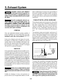
The exhaust system must extend a minimum of 1
inch (25 mm) beyond the perimeter or bumper of the
vehicle. If the genset tailpipe is on the same side of
the vehicle as the compartment, try to terminate the
tailpipe aft of the genset air intake to reduce the pos-
sibility of exhaust recirculation. Direct the exhaust
down and to the rear. See Figure 5-1.
1 INCH (25 mm)
MINIMUM
LAST TAILPIPE HANGER AS
CLOSE TO END AS PRACTICAL
FIGURE 5-1. EXHAUST TAILPIPE TERMINATION
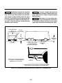
To reduce the possibility of damaging the tailpipe
and emitting exhaust gases under the vehicle, be
sure no part of the exhaust system intrudes into the
departure angle or approach angle unless it is ade-
quately protected by a skid bar or other protection
device. See shaded areas in Figure 5-2 on Page
5-2 for typical mounting locations.
WARNING
Exhaust gas presents the hazard of
severe personal injury or death. Use only Onan
specified exhaust equipment with generator set
and support the system per kit instructions.

5-2
WARNING
Exhaust gas presents the hazard of
severe personal injury or death. Do not termi-
nate exhaust gas under vehicle. Do not termi-
nate exhaust system directly under any vent,
window, or opening that can be opened and that
is not permanently sealed from the vehicle liv-
ing space. Keep all openings closed when the
generator set is running.
CAUTION
Excessive exhaust back pressure
can cause engine damage. If tailpipe deflector is
used, make sure it is large enough to prevent
back pressure.
CAUTION
Water vapor can cause engine dam-
age. Do not connect the generator set exhaust
to the vehicle exhaust system, because water
vapor from one engine can damage the other.
DEPARTURE
ANGLE
SEALED WINDOW
TAILPIPE
(RV REAR VIEW)
SKID BARS
GROUND
SHADED ZONE IS AREA
OF RECOMMENDED
TAILPIPE INSTALLATION
AXLE LOWER
CLEARANCE
LINE
APPROACH
ANGLE
NO OPENINGS INTO THE VEHICLE’S INTERIOR, INCLUDING
ENTRY DOORS, ARE ALLOWED IN THE SHADED AREA
6 IN.
(152.4 mm)
TAILPIPE
TAILPIPE MUST EXTEND A MINIMUM
OF 1 INCH (25.4 mm) BEYOND THE
PERIMETER OF THE VEHICLE
FIGURE 5-2. APPROACH AND DEPARTURE ANGLES AND AXLE CLEARANCE LINE

5-3
TAILPIPE RECOMMENDATIONS
An exhaust tailpipe is
not
supplied because of varia-
tion in length requirements between RV manufac-
turers. Prior to installing an exhaust tailpipe, refer to
the following recommendations for additional tips
and safety considerations.
Use 1-1/2-inch O.D. (1-3/8-inch I.D.) 18 gauge alu-
minized steel or stainless steel tubing for the tail-
pipe.
WARNING
Exhaust gas presents the hazard of
severe personal injury or death. Do not use flex-
ible exhaust tailpipe since it can leak or break
due to road shock or vibration. Do not terminate
exhaust system under the vehicle. Direct ex-
haust gases away from any window, door, or
compartment openings. Do not operate the gen-
erator set without an exhaust tailpipe.
Use U-bolt type automotive muffler clamps marked
1-3/8 and double rubber, U-shaped shock mounted
hangers for supporting the exhaust system. (See
Figure 5-3.) If the tailpipe extends beyond 1-1/2 feet
(0.46 m) from the muffler, attach one or more auto-
motive tailpipe hangers every 2 to 3 feet (0.6 to 0.9
m) of tailpipe run. Support the exhaust system at or
near the perimeter of the vehicle to prevent the pipe
from being damaged and pushed up under the ve-
hicle skirt. Attach hangers to steel framework, not
wood or other floor materials Refer to Figures 5-4
and 5-5 on Pages 5-4 and 5-5 for a typical tailpipe
installation.
CAUTION
Excessive exhaust back pressure
can cause engine damage. If a tailpipe deflector
is used, make sure it is large enough to prevent
back pressure.
CAUTION
Water vapor can cause engine dam-
age. Do not connect the genset exhaust to the
vehicle exhaust system, because water vapor
from one engine can damage the other.
CAUTION
Angular mounting of muffler and
tailpipe hanger brackets can result in exhaust
system damage. Properly mounted hanger
brackets will absorb much road shock vibration
and prolong the usefulness of exhaust system
components. Mount muffler and tailpipe hanger
brackets directly above the component sup-
port, not at an angle. Do not twist the rubber
sections of any hangers.
3/4 INCH (19 MM)
MAXIMUM SLOT
(BOTH SIDES)
FIGURE 5-3. EXHAUST TAILPIPE CONNECTIONS
Page is loading ...
Page is loading ...
Page is loading ...
Page is loading ...
Page is loading ...
Page is loading ...
Page is loading ...
Page is loading ...
Page is loading ...
Page is loading ...
Page is loading ...
Page is loading ...
Page is loading ...
Page is loading ...
Page is loading ...
Page is loading ...
Page is loading ...
Page is loading ...
Page is loading ...
Page is loading ...
Page is loading ...
Page is loading ...
Page is loading ...
Page is loading ...
Page is loading ...
Page is loading ...
Page is loading ...
Page is loading ...
Page is loading ...
-
 1
1
-
 2
2
-
 3
3
-
 4
4
-
 5
5
-
 6
6
-
 7
7
-
 8
8
-
 9
9
-
 10
10
-
 11
11
-
 12
12
-
 13
13
-
 14
14
-
 15
15
-
 16
16
-
 17
17
-
 18
18
-
 19
19
-
 20
20
-
 21
21
-
 22
22
-
 23
23
-
 24
24
-
 25
25
-
 26
26
-
 27
27
-
 28
28
-
 29
29
-
 30
30
-
 31
31
-
 32
32
-
 33
33
-
 34
34
-
 35
35
-
 36
36
-
 37
37
-
 38
38
-
 39
39
-
 40
40
-
 41
41
-
 42
42
-
 43
43
-
 44
44
-
 45
45
-
 46
46
-
 47
47
-
 48
48
-
 49
49


Onan emerald plus series Installation guide
- Category
- Power generators
- Type
- Installation guide
Ask a question and I''ll find the answer in the document
Finding information in a document is now easier with AI
Related papers
Other documents
-
 Whirlwind WLF482 User manual
-
 Sportsman GEN7500DF Specification
-
 Rainier Outdoor Power Equipment R12000DF User manual
-
CUMMINS QD 3200 HDZAA Installation guide
-
-
-
Toro Muffler Kit, Z Master Z100 Series Mowers Installation guide
-
-
-
 Cummins Power Generation Onan MicroLite 4000 KY Installation guide


