Bradford White UCG-80H-125-3N User manual
- Category
- Water heaters & boilers
- Type
- User manual

238-50463-00F REV 2/17
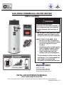
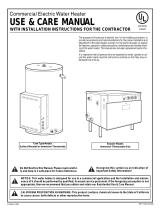
GAS-FIRED COMMERCIAL WATER HEATER
(Ultra Low NOx)
Ambler, PA 19002
Tech Service (800) 334-3393
Service Parts (800) 538-2020
Warranty Service (800) 531-2111
INSTALLATION/OPERATION MANUAL
WITH TROUBLESHOOTING GUIDE
PLACE THESE INSTRUCTIONS ADJACENT TO WATER HEATER AND NOTIFY OWNER TO KEEP FOR FUTURE REFERENCE
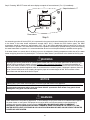
- Do not store or use gasoline or other
flammable vapors and liquids in the
vicinity of this or any other appliance.
- WHAT TO DO IF YOU SMELL GAS
Do not try to light any appliance.
Do not touch any electrical switch;
do not use any phone in your
building.
Immediately call your gas supplier
from a neighbor’s phone. Follow
the gas supplier’s instructions.
If you cannot reach your gas
supplier, call the fire department.
- For your family’s comfort, safety and
convenience, it is recommended this
water heater be installed and
serviced by a plumbing professional.
If the information in these
instructions is not followed exactly, a
fire or explosion may result causing
property damage, personal injury or
death.
WARNING

2
SECTION I: IMPORTANT INFORMATION
SECTION I: IMPORTANT INFORMATION ................ 2
SECTION II: SPECIFICATIONS................................. 5
SECTION III: GENERAL INFORMATION .................. 6
SECTION IV: INSTALLATION INSTRUCTIONS ....... 8
SECTION V: VENTING ............................................ 13
SECTION VI: WATER CONNECTIONS ................... 19
SECTION VII: GAS CONNECTIONS ....................... 23
SETION VIII: ELECTRICAL CONNECTIONS ......... 25
SECTION IX: OPERATING INSTRUCTIONS .......... 26
SECTION X: MAINTENANCE .................................. 35
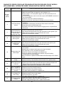
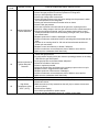
SECTION XI: DIAGNOSTIC AND
TROUBLESHOOTING GUIDE ................................. 39
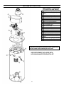
SECTION XII: PARTS LIST ..................................... 58
READ CAREFULLY
This gas-fired water heater is design certified by CSA International under the American National Standard, Z21.10.3
(as indicated on the rating plate) and CAN/CGA 4.3-M (as indicated on the rating plate) available from CSA Standards
Association, 5060 Spectrum Way, Mississauga, Ontario, CANADA L4W 5N6.
This water heater must be installed in accordance with local codes. In the absence of local codes, it must be installed
in compliance with the National Fuel Gas Code (ANSI Z223.1-Latest Edition), or in Canada CAN/CGA B149.1 Natural
Gas Installation Code (Latest Edition) or CAN/CGA B149.2 Propane Installation Code (Latest Edition).
The following terms are used throughout this manual to bring attention to the presence of hazards at various risk
levels, or to important information concerning product life.
Indicates special instructions on installation, operation
or maintenance, which are important but not related to
personal injury hazards.
NOTICE
Indicates a potentially hazardous situation, which, if
not avoided, could result in death, serious injury or
substantial property damage.
WARNING
Indicates potentially hazardous situation, which, if not
avoided, may result in moderate or minor injury or
property damage.
CAUTION
Indicates an imminently hazardous situation, which, if
not avoided, will result in death, serious injury or
substantial property damage.
DANGER
This water heater has a limited warranty. The warranty for this water heater is valid only if the water heater has been
installed, maintained and operated in accordance with these instructions.
NOTICE
TABLE OF CONTENTS

3
DANGER
DO NOT store or use gasoline or other flammable, combustible, or corrosive vapors and/or liquids in the vicinity of this or
any other appliance.
This water heater is equipped with an adjustable thermostat to control water temperature. Hot water temperatures
required for automatic dishwasher and laundry use can cause scald burns resulting in serious personal injury and/or
death. The temperature at which injury occurs varies with the person’s age and the time of exposure. The slower
response time of disabled persons increases the hazards to them. NEVER allow small children to use a hot water tap, or
to draw their own bath water. NEVER leave a child or disabled person unattended in a bathtub or shower.
Toxic chemical, such as those used for boiler treatment, must not be introduced into potable water used for space
heating.
This water heater must not be connected to an existing heating system or component(s) previously used with a non-
potable water heating appliance.
All piping components connected to this water heater for space heating applications must be suitable for use with
potable water.
WARNING
Improper installation, adjustments, alteration, service or maintenance can cause property damage, personal injury or
loss of life. Failure to follow all instructions in the proper order can cause personal injury or death. Read and understand
all instructions, including all those provided with the appliance before installing, starting-up, operating, maintaining or
servicing this appliance. Keep this manual and literature in legible condition with this water heater for reference by owner
and service technician.
This water heater requires regular maintenance and service to operate safely. Follow the instructions contained in this
manual.
Installation, maintenance, and service must be performed only by a qualified, skilled and knowledgeable installer or
service provider.
Installation is not complete unless a temperature and pressure relief valve is installed into the proper location at the top
of this water heater.
It is the responsibility of the installing contractor to see that all controls are correctly installed and are properly operating
when the installation is complete.
This water heater is suitable for installation on combustible flooring. Do not install water heater directly on carpeting.
DO NOT operate this water heater without first being certain it is filled with water.
DO NOT tamper with or alter the water heater and/or controls.
DO NOT operate water heater with jumpered or absent controls or safety devices.
DO NOT operate water heater if any external part has been under water. Immediately call a qualified service technician
to inspect the appliance and to replace any part of the control system including gas controls, which has been under
water.
DO NOT attempt to use this water heater with any gas other than the type listed on the rating plate. Do not attempt to
convert this water heater for use with a gas other than the type for which it is equipped. Failure to use the proper gas can
create an unsafe condition resulting in property damage, bodily injury, or death. Consult your local gas supplier or gas
company if there are any questions.
Incorrect operation of this appliance may create a hazard to life and property and will nullify the warranty.
DO NOT operate this water heater if the input rate exceeds the rate shown on the water heater rating plate.
This water heater contains very hot water under high pressure. Do not unscrew any pipe fittings nor attempt to
disconnect any components of this water heater without positively assuring the water is cool and is not under pressure.
Always wear protective clothing and equipment when installing, starting up or servicing this water heater to prevent scald
injuries. Do not rely on the temperature gauges to determine the temperature. Do not touch any components unless they
are cool.
This water heater must be properly vented and connected to an approved vent system in good condition. DO NOT
operate water heater with the absence of an approved vent system. A clean and unobstructed vent system is necessary
to allow noxious fumes that could cause injury or loss of life to vent safely and will contribute toward maintaining the
water heater’s efficiency.

4
To comply with NSF requirements this water heater is to be: Sealed to the floor with sealant, in a smooth and easily
cleanable way.
WARNING
This water heater needs fresh air for safe operation and must be installed so there are provisions for adequate
combustion and ventilation air. Insufficient air supply will cause a recirculation of combustion products resulting in
contamination that may be hazardous to life. This will result in carboning or sooting of the combustion chamber, burner,
and flue tubes and creates a risk of asphyxiation.
Water heater materials of construction, products of combustion and the fuel contain carbon monoxide, nitrogen oxides,
aldehydes and/or other toxic or harmful substances which can cause death or serious injury and which are known to the
state of California to cause cancer, birth defects and other reproductive harm. Always use proper safety clothing,
respirators and equipment when servicing or working nearby this water heater.
Flammable items, pressurized containers or any other potential fire hazardous articles must never be placed on or
adjacent to the water heater. Open containers of flammable material should not be stored or used in the same room with
this water heater.
Insulation blankets are not required for this water heater. This water heater meets or exceeds the ASHRAE/IES 90.1b
(latest edition) standards with respect to insulation and standby loss requirements.
Setting the water temperature to the maximum set point can result in scalding hot water delivered to the faucets. It is
highly recommended that the maximum setpoint be adjusted to the lowest temperature possible for the needs of the
installation. See following section in this Installation/Operation Manual to change the maximum setpoint limit (max
setpoint). Make sure the water heater control display is not in a public area that can result in the temperature settings
being improperly adjusted.
Hydrogen gas can be produced in an operating water heater that has not had water drawn from the tank for a long
period of time (generally two weeks or more). Hydrogen gas is extremely flammable. To prevent the possibility of injury
under these conditions, we recommend the hot water faucet to be open for several minutes at the kitchen sink before
you use any electrical appliance, which is connect to the hot water system. If hydrogen is present, there will be unusual
sounds such as air escaping through the pipes as hot water begins to flow. Do not smoke or have open flame near the
faucet at the time it is open.
Basements, crawl spaces, closets and areas below ground level will serve as pockets for accumulation of leaking gas.
Before lighting, smell all around the appliance area for gas. Be sure to smell next to the floor.
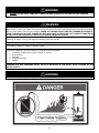
IF YOU SMELL GAS:
DO NOT try to light any appliance.
DO NOT touch any electric switch; do not use any telephone in your building.
Immediately call your gas supplier from a telephone in another building. Follow the gas supplier’s instructions.
If you cannot reach your gas supplier, call the fire department.
DO NOT OPERATE THE APPLIANCE UNTIL THE LEAKAGE IS CORRECTED!
WARNING

5
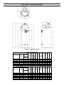
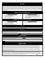
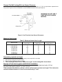
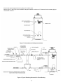
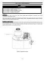
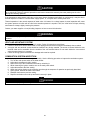
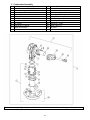
SECTION II: SPECIFICATIONS
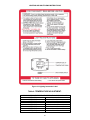
Figure 1. Dimensional Layout.
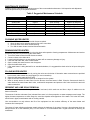
Table 1. Specifications.
Model Description A
Floor to
Top of
Vent
(in.)
B
Vent
Dia.
(in)
C
Floor
to
Cold
Water
Conn.
(in)
D
Floor
to T&
P
(in)
E
Floor
to Hot
Water
Conn.
(in)
F Floor
to Top
of
Water
Heater
(in)
G
Floor
to Gas
Conn.
(in)
Water
Conn.
Dia.
(in.)
Gas
Conn.
Dia.
(in.)
Relief
Valve
(in.)
Model Number
Capacity
(Gal.)
Input BTU/Hr.
NAT. & L.P.
UCG100H199 100 199,999 73 ¼ 6 10 52 ½ 55 ½ 69 ¾ 63 ¼ 1 ½ ¾ ¾
UCG100H270 100 270,000 73 ¼ 6 10 52 ½ 55 ½ 69 ¾ 63 ¼ 1 ½ ¾ 1
UCG100H399 98 399,999 77 ¼ 8 10 52 ½ 55 ½ 69 ¾ 63 ¼ 1 ½ ¾ 1
UCG80H125 80 125,000 63 5 10 44 47 61 ¼ 55 ¾ 1 ½ ¾ ¾
UCG80H199 80 199,999 64 ¾ 6 10 44 47 61 ¼ 55 ¾ 1 ½ ¾ ¾
UCG80H270 80 270,000 64 ¾ 6 10 44 47 61 ¼ 55 ¾ 1 ½ ¾ 1
UCG80H399 80 399,999 68 ¾ 8 10 44 47 61 ¼ 55 ¾ 1 ½ ¾ 1
Model Description A
Floor to
Top of
Vent
(mm)
B
Vent
Dia.
(mm)
C
Floor
to
Cold
Water
Conn.
(mm)
D
Floor
to
T&P
(mm)
E
Floor
to Hot
Water
Conn.
(mm)
F Floor
to Top
of Wate
r
Heater
(mm)
G Floor
to Gas
Conn.
(mm)
Water
Conn.
Dia.
(mm)
Gas
Conn.
Dia.
(mm)
Relief
Valve
(mm)
Model Number
Capacity
Liters
Input kW/Hr.
NAT. & L.P.
UCG100H199 379 58.6 1861 152 254 1334 1410 1772 1607 38 19 19
UCG100H270 379 79.1 1861 152 254 1334 1410 1772 1607 38 19 25
UCG100H399 371 117.2 1962 203 254 1334 1410 1772 1607 38 19 25
UCG80H125 303 36.6 1600 127 254 1118 1194 1556 1391 38 19 19
UCG80H199 303 58.6 1899 152 254 1118 1194 1556 1391 38 19 19
UCG80H270 303 79.1 1899 152 254 1118 1194 1556 1391 38 19 25
UCG80H399 303 117.2 2000 203 254 1118 1194 1556 1391 38 19 25

6
SECTION III: GENERAL INFORMATION
FEATURES
This water heater contains the following features:
MAIN POWER ON/OFF SWITCH
The front panel of this water heater has an ON/OFF switch, which has markings when the main power is turned on to
indicate power to the water heater.
COMBUSTION SYSTEM
This water heater is equipped with a self-compensating negative pressure pre-mix combustion system. As the blower
operates, air is drawn in through the air intake and into a venturi, which pulls gas from the gas valve. The gas and air is
then mixed in the combustion blower and sent through the transition tube into the burner. The Direct Spark Ignition
System (DSI) then ignites the gas/air fuel mixture to produce flue products (combustion). The flame sensor signals the
ignition control board (described below), that a flame is present.
HONEYWELL INTEGRATED CONTROL
Consists of a control board and a water heater display. An attractive digital water heater display is on the top front of the
water heater for precisely setting and displaying the temperature setpoint and monitoring the status of the water heater.
Pressing the temperature UP and DOWN buttons changes the temperature setpoint. The temperature format may be
displayed in degrees F or degrees C. The water heater display will show diagnostic codes in the event the water heater
needs servicing. The temperature readings of the tank sensor can be monitored in Service Mode. Also in Service Mode,
the display can show up to 10 previous error codes to further aid in servicing the water heater.
The single control board has plug in wiring harnesses to reduce the chance of mis-wiring. The control board controls all
ignition, temperature, and combustion blower functions. The control board controls the combustion blower, ignition
timings, and gas valve to control the combustion system in order to maintain the desired tank temperature. The sequence
of operation is described in detail in the Diagnostic Section at the back of this Installation and Operating Instruction
Manual.
ADJUSTABLE THERMOSTAT
This water heater is equipped with an adjustable thermostat as part of the Integrated Control System to control water
temperature. Hot water temperatures required for automatic dishwasher and laundry use can cause scald burns resulting
in serious personal injury and/or death.
The temperature may be adjusted from about 70°F (21°C) to about 180°F (82°C). The thermostat was adjusted to 70°F
(21°C) before the water heater was shipped from the factory. It is recommended that lower temperatures be used to avoid
the risk of scalding. Refer to the “Warnings” and the section on SCALDING in “Section V: Water Connections”. It is further
recommended, in all cases, that the water temperature be set for the lowest temperature, which satisfies your hot water
requirements for the installation. This will also provide the most energy efficient operation of the water heater and
minimizes scale formation.
Setting the water heater temperature at 120°F (49°C) will reduce the risk of scalds. Some states require setting lower
temperatures for specific installations.
The top immersion well of the single sensor control also contains a redundant sensor for the high limit (energy cutoff). The
high limit circuit interrupts the main burner gas flow should the water temperature exceed approximately 200°F (93°C).
Error code “65” will be shown on the water heater control display if the high limit temperature has been exceeded.
Should the high limit switch activate, it must be manually reset. This should only be done by a service technician after the
cause of overheating has been corrected. Refer to the section on “Accessing Service Mode on the Display” in the
Diagnostic section of this Installation and Instruction Manual.
Contact your qualified installing contractor, service provider or manufacturer listed on the rating plate if continued high
limit operation occurs.
LATCHES
The latches allow easy access for servicing the water heater from the top. Simply remove the two latches for servicing
and re-latch upon completion. No tools are required to obtain access to the top of the water heater.

7
DISHWASHING MACHINE REQUIREMENTS
All dishwashing machines meeting the National Sanitation Foundation requirements are designed to operate with water
flow pressures between 15 and 25 pounds per square inch. Flow pressures above 25 pounds per square inch, or below
15 pounds per square inch, will result in improperly sanitized dishes.
The National Sanitation Foundation also recommends circulation of 180°F water. Where this is done, the circulation
should be very gentle so that it does not cause any unnecessary turbulence inside the water heater. The circulation
should be just enough to provide 180°F water at the point of take-off to the dishwashing machine. Adjust flow by means of
the valve in the circulation line.
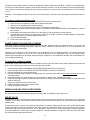
SACRIFICIAL ANODES – Three sacrificial anode rods have been installed in the tank head to extend tank life. The
anode rods should be inspected periodically for corrosion and replaced when necessary to prolong tank life. Water
conditions in your area will influence the time interval for inspection and replacement of the anode rods. The use of a
water softener may increase the speed of anode consumption. More frequent inspection of the anodes is needed when
using softened (or phosphate treated) water. Contact the installing contractor, or service provider that installed the
water heater or the manufacturer listed on the rating plate for anode replacement information.
WARNING
This product contains one or more chemicals known to the State of
California to cause cancer, birth defects, or reproductive harm.
Keep clear of combination temperature and pressure relief valve discharge line outlet. The discharge may be
hot enough to cause scald injury. The water is under pressure and may splash.
For protection against excessive temperatures and pressure, install temperature and pressure protective equipment
required by local codes, but not less than a combination temperature and pressure relief valve certified by a
nationally recognized testing laboratory that maintains periodic inspection of production of listed equipment or
materials as meeting the requirements of the Standard for Relief Valves and Automatic Gas Shutoff Devices for Hot
Water Supply Systems, ANS Z21.22 and the Standard CAN1-4.4 Temperature, Pressure, Temperature and
Pressure Relief Valves and Vacuum Relief Valves. The combination temperature and pressure relief valve must be
marked with a maximum set pressure not to exceed the maximum working pressure of the water heater. The
combination temperature and pressure relief valve must also have an hourly rated temperature steam BTU
discharge capacity not less than the hourly rating of the water heater.
Install the combination temperature and pressure relief valve into the opening provided and marked for this purpose
on the water heater.
Note: Some models may already be equipped or supplied with a combination temperature and pressure relief valve.
Verify that the combination temperature and pressure relief valve complies with local codes. If the combination
temperature and pressure relief valve does not comply with local codes, replace it with one that does. Follow the
installation instructions above on this page.
Install a discharge line so that water discharged from the combination temperature and pressure relief valve will exit
within six (6) inches (15.2 cm) above, or any distance below the structural floor and cannot contact any live electrical
part. The discharge line is to be installed to allow for complete drainage of both the combination temperature and
pressure relief valve and the discharge line. The discharge opening must not be subjected to blockage or freezing.
DO NOT thread, plug or cap the discharge line. It is recommended that a minimum clearance of four (4) inches
(10.2 cm) be provided on the side of the water heater for servicing and maintenance of the combination temperature
and pressure relief valve.
Do not place a valve between the combination temperature and pressure relief valve and the tank.
WARNING

8
SECTION IV: INSTALLATION INSTRUCTIONS
Sacrificial anode rods have been installed in the tank head of the water heater to extend tank life. The removal of these
anodes, except for inspection and/or replacement, will nullify the warranty. In areas where water is unusually active, an
odor may occur at the hot water faucet due to a reaction between the sacrificial anode and the impurities in the water. If
this should happen, alternative anodes may be purchased from the supplier that installed this water heater. This will
minimize the odor while protecting the tank. Additionally, the water heater should be flushed with appropriate dissolvers to
eliminate any bacteria.
Note: For California installation this water heater must be braced, anchored, or strapped to avoid falling or moving
during an earthquake. See instructions for correct installation procedures. Instructions may be obtained from
DSA Headquarters Office, 1102 Q Street, Suite 5100, Sacramento, California 95811.
This water heater MUST be installed indoors out of the wind and weather.
INSTALLATION OF THIS WATER HEATER REQUIRES ABILITY EQUIVALENT TO THAT OF A LICENSED
TRADESPERSON IN THE FIELD INVOLVED. PLUMBING, AIR SUPPLY, VENTING, GAS SUPPLY AND
ELECTRICAL WORK ARE REQUIRED.
DO NOT ATTEMPT TO LIGHT ANY GAS APPLIANCE IF YOU ARE NOT CERTAIN OF THE FOLLOWING:
Liquefied petroleum gases/propane gas and natural gas have an odorant added by the gas supplier that aids in
detection of the gas.
Most people recognize this odor as a “sulfur” or “rotten egg” smell.
Other conditions, such as “odorant fade” can cause the odorant to diminish in intensity, or “fade”, and not be as
readily detectable.
If you have a diminished sense of smell, or are in any way unsure of the presence of gas, immediately contact
your gas supplier from a telephone in another building.
Gas detectors are available. Contact your gas supplier or plumbing professional for more information.
Liquefied petroleum gases/propane gas is heavier than air and will remain at floor level if there is a leak. Basements,
crawl spaces, closets and areas below ground level will serve as pockets for accumulation of leaking gas. Before
lighting, smell all around the appliance area for gas. Be sure to smell next to the floor.
IF YOU SMELL GAS:
Do not try to light any appliance.
Do not touch any electric switch; do not use any telephone in your building.
Immediately call your gas supplier from a telephone in another building. Follow the gas supplier’s instructions.
If you cannot reach your gas supplier, call the fire department.
DO NOT OPERATE THE APPLIANCE UNTIL THE LEAKAGE IS CORRECTED!
This water heater must be located in an area where leakage of the tank, water line connections, or the combination
temperature and pressure relief valve will not result in damage to the area adjacent to the water heater or to lower
floors of the structure. When such locations cannot be avoided, a suitable drain pan must be installed under the water
heater. The drain pan depth must be suitable for draining and collecting water, and have a minimum length and width
of at least four (4) inches (10.0 cm) measured from the jacket of the water heater. The drain pan, as described above,
can be purchased from your plumbing professional. The water heater might need to be placed on blocks inside drain
pan to fit in standard size pan. The drain pan must be piped to an adequate drain. The piping must be at least ¾ inch
(2.0 cm) in diameter and pitched for proper drainage.
Water heaters are heat producing appliances. To avoid damage or injury there must be no materials stored against the
water heater and proper care must be taken to avoid unnecessary contact (especially by children) with the water heater
components. UNDER NO CIRCUMSTANCES SHALL FLAMMABLE MATERIALS, SUCH AS GASOLINE OR PAINT
THINNER BE USED OR STORED IN THE VICINITY OF THIS WATER HEATER, VENT-AIR INTAKE SYSTEM OR IN
ANY LOCATION FROM WHICH FUMES COULD REACH THE WATER HEATER OR VENT-AIR INTAKE SYSTEM.
Failure to adhere to these installation and operating instructions may create a hazard to life and property and will nullify
the warranty.
WARNING

9
The National Fuel Gas Code (ANSI Z233.1- latest edition) or in Canada The Natural Gas Installation Code
CAN/CGA (B149.1 - latest edition), expressly prohibits the following:
a. Installation of a water heater in a bathroom, bedroom, or any occupied room normally kept closed.
b. Installation of a water heater in a garage, unless the unit is installed so that the burner and ignition devices are at
least eighteen (18) inches (45.8 cm) above floor level and protected to avoid damage by a moving vehicle.
If the buildings cold water supply has a back-flow preventer, check valve or water meter with check valve, provisions
for thermal expansion of water in the hot water system must be provided.
CAUTION
This water heater MUST NOT be installed in any location where gasoline or flammable vapors are likely to be
present, unless the installation is such to eliminate the probable ignition of gasoline or flammable vapors.
The location of this water heater is of the utmost importance. Before installing this water heater, you should read the
Installation section of these instructions. After reading these Installation and Operating Instructions, select a location for the
water heater where the floor is level and is easily accessible to water lines, gas supply (type identified on the rating plate),
an adequate open drain, and a chimney or exhaust gas vent. DO NOT locate the water heater where water lines could
be subjected to freezing temperatures. Make sure the cold water pipes are not located directly above the gas
control box or any other electrical control so that condensate during humid weather does not drip on the controls.
This installation must allow access to the front of the water heater and adequate clearance must be provided for servicing
and operating this water heater. The water heater may be installed on either a combustible or non-combustible floor. If the
water heater is to be installed directly on carpeting, it must be installed on top of a metal or wood panel (or equivalent)
extending beyond the full width and depth of the appliance by at least three (3) inches (7.6 cm) in any direction or, if the
appliance is to be installed in an alcove or closet, the entire floor must be covered by the panel. The minimum clearances
to combustibles for this water heater are given in the following pages. A minimum of 24 inches front clearance must be
provided for inspection and servicing. Adequate clearances must be provided for easy access to controls by service
personnel to enable proper cleaning, servicing, and operation of the water heater.
Water heater corrosion and component failure can be caused by the heating and breakdown of airborne chemical vapors.
Examples of some typical compounds that are potentially corrosive are: spray can propellants, cleaning solvents,
refrigerator and air conditioning refrigerants, swimming pool chemicals, calcium and sodium chloride, waxes and process
chemicals. These materials are corrosive at very low concentration levels with little or no odor to reveal their presence.
UNPACKING
1. Inspect carefully for any signs of damage
2. All equipment is carefully manufactured, inspected and packed.
3. Any claims for damage or shortage in shipment must be filed immediately with the manufacturer noted on the
rating plate label.
LOCATE WATER HEATER
1. Locate water heater in front of final position before removing crate.
2. LOCATE so that venting connections will be short and direct.
3. THIS WATER HEATER IS SUITABLE FOR INSTALLATION ON COMBUSTIBLE FLOOR.
4. Proper venting practices must be considered when selecting a location for this water heater. For exact venting
specifications, please consult the Venting section of these Installation and Operating Instructions.
5. It is recommended that minimum clearances shown in figure 2b be provided on the sides and top of the water
heater for servicing and maintenance of the water heater.
6. Increase distances to provide clearance for servicing.
DAMAGE TO THE WATER HEATER CAUSED BY EXPOSURE TO CORROSIVE VAPORS IS NOT COVERED BY
THE WARRANTY. DO NOT OPERATE THE WATER HEATER IF EXPOSURE HAS OR WILL OCCUR. DO NOT
STORE ANY POTENTIALLY CORROSIVE COMPOUNDS IN THE VICINITY OF THE WATER HEATER.
NOTICE

10
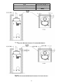
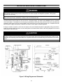
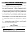
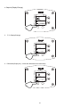
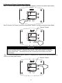
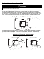
Input Front, sides and Rear “A”
Less than or equal to 270,000 BTUH 0 in. (0.0 CM)
399,999 BTUH 0 in. (0.0 CM) (2 in. Rear
ONLY)
Figure 2a. Minimum Clearance To Combustible Material.
Figure 2b. Recommended Minimum Clearances For Service Access.

11
REMOVE CRATE
1. Remove all banding and pry off crate sides carefully so as not to damage the water heater.
2. Carefully roll/lift the water heater from the crate base.
CAUTION
Do not drop water heater. Do not bump water heater jacket against floor.
Do not bump exhaust vent pipe against crate or other objects. This will damage the heater and cause it to be inoperable
or create nuisance problems.
MOVE WATER HEATER TO PERMANENT POSITION by sliding or walking.
INSTALL TEMPERATURE AND PRESSURE RELIEF VALVE (if not already installed).
DANGER
Temperature setting should not exceed safe temperature at fixtures. See water temperature control warning in Section
VI, “Water Connections”. If higher preheat temperatures are necessary to obtain adequate booster output, add an ASSE
approved mixing device for hot water supplied to fixtures.
WARNING
Temperature and pressure relief valve discharge piping must be piped near floor to eliminate potential of severe burns.
Do not pipe in any area where freezing could occur. Do not install any shut-off valves, plugs or caps to the temperature
and pressure relief valve or piping.
This water heater must be located in an area where the general public does not have access to set temperatures.
AIR REQUIREMENTS
1. Do not obstruct the flow of ventilating air.
2. For safe operation, adequate air is needed for combustion and ventilation. Sooting may result in serious damage
to the water heater and risk of fire or explosion. It can also create a risk of asphyxiation. Such a condition often
will result in a yellow, luminous burner flame, causing carboning or sooting of the combustion chamber, burner
and flue tubes.
CONFINED SPACES
If the water heater is installed in a confined space (volume is less than 50 ft.
3
/1000 BTU (15 m
3
/0.29 kW) per hour of the
total input rating of all gas appliances in that space), air must be supplied through two permanent openings. One opening
must be within 12 inches (30.5 cm) from the top of the enclosure and one within 12 inches (30.5 cm) of the bottom. The
openings must be protected by metal louvers or 1/4” (6.4 mm) min. mesh metal screen. The size of the openings are as
follows:
IMPORTANT-The flow of combustion and ventilating air must not be obstructed.
MECHANICAL EXHAUSTING OF ROOM AIR - Where an exhaust fan is installed in the same room with this
water heater and combustion air is drawn from inside the room, sufficient openings for air must be provided in the
walls. UNDERSIZED OPENINGS WILL CAUSE AIR TO BE DRAWN INTO THE ROOM THROUGH THE WATER
HEATER’S VENTING SYSTEM, CAUSING POOR COMBUSTION THAT MAY BE HAZARDOUS TO LIFE. SOOTING
MAY RESULT IN SERIOUS DAMAGE TO THE WATER HEATER AND RISK OF FIRE OR EXPLOSION, WHICH CAN
ALSO CREATE A RISK OF ASPHYXIATION. Refer to local codes and /or National Fuel Gas Code (ANSI Z223.1-
Latest Edition), or in Canada CAN/CGA B149.1 Natural Gas Installation Code (Latest Edition) or CAN/CGA B149.2
Propane Installation Code (Latest Edition) for proper air opening sizing.
WARNING

12
1. If the openings communicate directly with an additional room(s) of sufficient volume, each opening must have a
minimum free area opening of 1 in.
2
/1000 BTU (2.54cm
2
/0.29kW) per hour of the total input rating of all gas
appliances in the confined space, but not less than 100 in.
2
(254 cm
2
).
2. If the openings communicate with the outdoors through horizontal ducts, each opening must have a minimum free
area of 1 in.
2
/2000 BTU (2.54cm
2
/0.59kW) per hour of the total rating of all gas appliances in the enclosure.
3. If the openings communicate directly with the outdoors or through vertical ducts with the outdoors, each opening must
have a minimum free area of 1 in.
2
/4000 BTU (2.54cm
2
/1.18kW) per hour of the total rating of all gas appliances in
the enclosure.
ALL AIR FROM INSIDE THE BUILDING
The confined space must be provided with two permanent openings communicating directly with an additional room(s) of
sufficient volume so that the combined volume of all spaces meets the criteria for an unconfined space. The total input of
all gas utilization equipment installed in the combined space must be considered in making this determination. Each
opening must have a minimum free area of 1 in.
2
/1000 BTU (2.54cm
2
/0.29kW) per hour of the total input rating of all gas
utilization equipment in the confined space, but not less than 100 square inches (254cm
2
). One opening must be within 12
inches (30.5 cm) of the top and one within 12 inches (30.5 cm) of the bottom of the enclosure.
UNCONFINED SPACES
In unconfined spaces in buildings, infiltration may be adequate to provide air for combustion, ventilation and dilution of flue
gases. However, in buildings of tight construction (for example, weather stripping, heavily insulated, caulked, vapor
barrier, etc.), additional air may need to be provided using the methods described above under CONFINED SPACES: All
Air From Outdoors or SPECIALLY ENGINEERED INSTALLATIONS.
SPECIALLY ENGINEERED INSTALLATIONS
The requirements noted under CONFINED SPACES above must not necessarily govern when special engineering,
approved by the authority having jurisdiction, provides an adequate supply of air for combustion, ventilation, and dilution
of flue gases.
CHEMICAL VAPOR CORROSION
Corrosion of the flue ways and vent system will occur if air for combustion contains certain chemical vapors. Such
corrosion may result in poor combustion and create a risk of asphyxiation, as well as reducing the life of the water
heater. Spray can propellants, cleaning solvents, refrigerator and air conditioning refrigerants, swimming pool
chemicals, calcium and sodium chloride, waxes and process chemicals are corrosive. Products of this sort should not
be stored near the water heater or outside by the air intake (if applicable).
The draft hood relief opening of the water heater and combustion air inlet must be in the same atmospheric pressure
zone. Large exhaust fans in kitchens and other locations can lower the air pressure inside an enclosure and interfere
with the proper operation and venting of the water heater. In these cases, the water heater should be installed in a
separate room with the combustion and ventilation air supplied directly from outdoors as previously described.
CAUTION

13
SECTION V: VENTING
This water heater has been shipped with a draft diverter for which it was designed with reference to the horizontal and
vertical planes, its certified category I, per latest ANSI Z 21.10.3-2015.CSA 4.3-2015 revision. Refer to the latest edition
of the National Fuel Gas Code (ANSI Z223.1-latest edition), or in Canada, the Natural Gas and Propane installation Code
(B149.1-00 latest edition). If removed, the draft diverter must be replaced in the same position and secured to the jacket
top by the screws with which it was installed.
This water heater must be connected to a lined masonry chimney or venting system approved by local codes or
ordinances. The vent connector used to attach the draft hood outlet to the chimney or approved vent must be of the same
diameter as the draft diverter outlet or larger. For proper venting in certain installations, a larger vent connector may be
needed. Consult venting tables in ANSI standard (Z223.1- latest edition), National Fuel Gas Code and CAN/CGA (B149.1
or B149.2-latest editions) Natural Gas and Propane Installation Code, or local code officials for proper application for your
area.
Optional Intake Venting
The venting instructions must be followed to avoid restricted combustion or recirculation of flue gases. Such
conditions cause sooting or risks of fire and asphyxiation.
WARNING
The intake vent system must be properly installed. Failure to properly install the vent system could result in property
damage, personal injury, or death.
Use only the vent terminals provided or factory authorized terminals for venting this water heater.
The water heater requires its own separate intake venting system.
Do not terminate the venting where noise from intake venting will be objectionable. This includes locations close to or
across from windows and doors. Avoid anchoring the intake vent pipes directly to framed walls, floors, or ceilings unless
rubber isolation pipe hangers are used. This prevents any vibrations from being transmitted into the living spaces.
Do not exceed the venting distances or the number of elbows listed in this manual. Exceeding the maximum venting
distances may cause the water heater to malfunction or cause an unsafe condition.
DO NOT operate this water heater until the venting installation is complete and the piping completed. Failure to
complete installation before operation can result in property damage, personal injury, or death.
The venting system must be installed properly following all local codes or in the absence of local codes, the latest
edition of the National Fuel Gas Code (ANSI Z223.1- latest edition), or in Canada, The Natural Gas Installation Code
(B149.1-00 latest edition) or CAN/CGA B149.2 Propane Installation Code (Latest Edition).
Failure to properly install the venting system could result in property damage, personal injury, or death.
Carefully inspect the venting system of a replacement water heater installation before connecting to the venting
system. All joints in the vent connector must be securely fastened with screws and fit tightly together. Inspect the
venting system for signs of deterioration (rust and perforation) and replace any sections that are not in good condition.
The chimney must be lined and in good condition. Check to make sure the venting system is properly sized for the
water heater. If the venting system was previously sized for another gas appliance that has been removed, the venting
system may now be too large. Refer to the latest edition of the National Fuel Gas Code (ANSI Z223.1-latest edition), or
in Canada, the Natural Gas and Propane Installation Code (B149.1-00 latest edition) for the correct sizing of venting
systems and common venting with another gas appliance. Do not vent this water heater into the venting system of
another gas appliance designed to vent under positive pressure.
The water heater should be installed as close as practical to the venting system to minimize the vent connector length
required. Refer to local codes for the distance limitations on vent connector lengths. At the completion of the water
heater installation, the burner and venting system must be checked for proper operation with all other commonly
vented appliances in operation. Check for spillage of flue products around the outside relief opening of the drafthood
after several minutes of operation. The flame from a match should be drawn into the drafthood. Do not use the water
heater or connected equipment if spillage is detected until the problem is corrected. Refer to the latest edition of the
National Fuel Gas Code, or in Canada, the Natural Gas and Propane Installation Code for complete details on the
“Procedure to Be Followed to Place Equipment in Operation”.
WARNING

14
NOTICE
For installations in Canada, field supplied vent piping must comply with CAN/CGA B149.1 (latest edition) and be certified to the
Standard For Type BH, Class II, 65°C, Gas Venting Systems, ULC S636. Components of this listed system shall not be interchanged
with other vent systems or unlisted pipe/fittings. All components and specified primers and cements of the certified vent system must
be from a single system manufacturer and not intermixed with other system manufacturer’s vent system parts. The supplied vent
connector and vent termination are certified under ULC S636 and are also certified as part of the water heater. Refer to the following
tables for approved venting materials, primers, and cements. All approved primers and cements are to be used within their marked
time limitations.
Approved Venting Materials
For installations in the US only
PVC Sch. 40, 80 (ASTM D-1785)
PVC DWV (ASTM-D2665)
CPVC Sch. 40, 80 (ASTM-F441)
CPVC (ASTM D2846)
ABS Sch. 40 DWV (ASTM D2661)
For installations in CANADA
ULC S636 approved CAN-COM VENTING SYSTEM
schedule 40 PVC for flue gas venting rated Class II,
65°C (components provided with water heater)
IPEX ULC S636 approved schedule 40 PVC (all other
vent pipe/ fittings)
Approved Primers and Cements
For installations in the US only
PVC and CPVC Primer (ASTM F-656)
PVC Cement (ASTM D-2564)
CPVC Cement (ASTM F493)
ABS Primer and Cement (ASTM D-2235)
For installations in CANADA
IPEX ULC S636 approved PVC Primer and Cement for
flue gas venting rated Class II, 65°C
NOTICE
Use of cellular core PVC (ASTM F891). Cellular core CPVC, or Radel® (polyphenosulfone) in non-metallic venting systems is
prohibitied, and covering non-metallic venting with thermal insulation is prohibited.
NOTICE
Before beginning installation of any vent pipe, read the vent pipe manufacturer’s installation instructions.
Do not install the water heater in any location where the ambient temperature may fall below freezing. Water heater must be protected
from freezing downdrafts during shutdown periods.
CAUTION
The vent shall terminate a minimum of 12 inches above expected snowfall level to prevent blockage of vent termination.
The horizontal centerline of the exhaust vent terminal (if applicable) must not be located lower than the horizontal centerline of the air
intake terminal if vented through the same wall.
A service drain loop must be installed in the drain tubing to serve as a condensate trap to prevent flue gases from escaping into the
room.
NEVER locate the air intake where exhaust gases from other appliances can be introduced into the intake.
CAUTION
Check to make sure flue gases do not recirculate into the air intake terminal when using direct venting. If the water heater is having
service issues, flue recirculation may be a contributing factor. Even when the minimum vent terminal separation distances are
followed, recirculation may still occur depending upon the location outside the building, the distance from other buildings, proximity to
corners, weather conditions, wind patterns, and snow depth. Periodically check to make sure that flue recirculation is not occurring.
Signs of flue gas recirculation include frosted or frozen intake terminals, condensate in the intake terminal and venting system,
oxidation or white chalk material on the flame sensor or igniter shield. Correction to flue recirculation may involve relocating the air
intake to another side of the building, or using inside air for combustion. Check to be sure the intake is not obstructed, especially
during periods of below freezing weather.
High levels of dust and debris such as road and construction dust, insects, and tree pollen may clog the burner resulting in poor
performance and damage to the water heater. Avoid air intake locations where debris can be created such as exhaust ventilation
hoods, gravel parking lots, and near outdoor spotlights that attract bugs. For these installations, an air intake filter kit, part number 239-
47330-00A, is available as an accessory service part from the installer of this water heater. The air intake filter kit is not designed to
filter out airborne contaminants or chemicals that may damage the water heater.

15
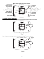
Figure 3. Intake Vent Terminal Clearances (Referencing Other Appliance Venting Locations).
Canadian
Installations
1
US Installations
2
Canadian
Installations
1
US Installations
2
A= Clearance above
grade, veranda,
porch, deck or
balcony
12 inches
(30 cm)
12 inches
(30 cm)
H= Clearance to each side
of center line extended
above meter/regulator
assembly
3 feet (91 cm) within a
height 15 feet (4.6 m)
above the
meter/regulator
assembly
*b
B= Clearance to window
or door that may be
opened
36 inches
(91 cm)
4 feet (1.2 m)
below or to the
side of opening;
12 inches (30
cm) above
opening
I= Clearance to service
regulator vent outlet or
oil tank vent
36 inches
(91 cm)
*b
C= Clearance to
permanently closed
window
*b *b J= Clearance to non-
mechanical air supply
inlet to building or the
combustion air inlet to
any other appliance
36 inches
(91 cm)
4 feet (1.2m)
below or to side
of opening; 12
inches (30 cm)
above opening.
D= Vertical clearance to
ventilated soffit
located above the
terminal within a
horizontal distance of
2 feet (61 cm) from
the center line of the
terminal
*b *b K= Clearance to a
mechanical air supply
inlet
6 feet
(1.83 m)
3 feet (91 cm)
above if within
10 feet
horizontally
E= Clearance to
unventilated soffit
*b *b L= Clearance above paved
sidewalk or paved
driveway located on
public property
7 feet
(2.13 m)†
7 feet
(2.13 m)†
F= Clearance to outside
corner
*b *b M= Clearance under a
veranda, porch, deck, or
balcony
12 inches (30 cm) ‡ *b
G= Clearance to inside
corner
36 inches
(91 cm)*a
36 inches
(91 cm)*a
In accordance with the current CAN/CGA-B149 Installation Codes.
2
In accordance with the current ANSI Z223.1-(Latest Edition)/NFPA 54 National Fuel Gas Code.
† A vent shall not terminate directly above a sidewalk or paved driveway that is located between two single-family dwellings and serves both
dwellings.
‡ Permitted only if a veranda, porch, deck or balcony is fully open on a minimum of two sides beneath the floor.
*a) A minimum clearance value determined by testing in accordance with section 2.20.
*b) “Clearance in accordance with local installation codes and the requirements of the gas supplier”.

16
Vent pipes serving power vented appliances are classified by building codes as “vent connectors”. Required clearances
from combustible materials must be provided in accordance with information in this manual under LOCATION OF
WATER HEATER and CLEARANCES, and with National Fuel Gas Code and local codes.
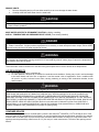
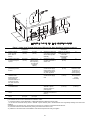
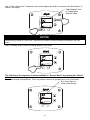
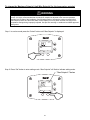
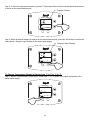
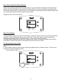
Horizontal Installation
In a horizontal application, it is important that moisture is not to be allowed to buildup in the intake vent pipe. To prevent
this from happening, the pipe should be installed with a slight downward slope so the moisture will run back away from
the water heater. The vent system must be supported every 5 feet of vertical run and every 3 feet of horizontal run of vent
pipe length.
CAUTION
Failure to properly support the vent piping with hangers and clamps may result in damage to the water heater or venting
system.
Figure 4. Typical Horizontal Intake Vent System.
Clearance to combustibles for all venting pipes and terminals
For installations in the US
0” minimum
For installations in the CANADA
Refer to vent pipe and terminal manufacturer’s installation
instructions for clearances to combustibles
DO NOT place insulation or other materials in the required clearance spaces between the venting to combustible material unless
otherwise specified.
WARNING! DO NOT USE 2”
VENT WITH UCG100H399
MODELS

17
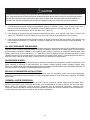
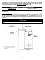
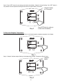
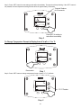
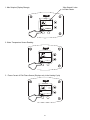
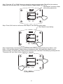
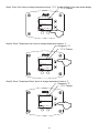
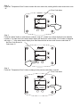
Vertical Installation
Vertical venting system must be supported every 5 feet of vertical run and every 3 feet of horizontal run of vent pipe
length.
CAUTION
Failure to properly support the vent piping with hangers and clamps may result in damage to the water heater or venting
system.
Figure 5. Typical Vertical Intake Vent System Installation.
WARNING! DO NOT USE 2”
VENT WITH UCG100H399
MODELS

18
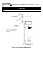
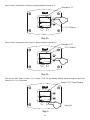
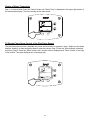
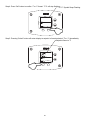
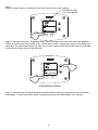
Through The Wall Venting With Low Ground Clearance:
When venting cannot exit through the wall at a height greater than or equal to 12” (30.5 cm) (and above expected snow
level) from the ground, then the installation must be modified as shown below (see Figure 6).
Figure 6. Vent Terminal (Low Ground Clearance
).
Maximum Vent Length
Table 2. Maximum Intake Vent Length.
Model Number
Max Vent
Length (feet) 2”
Max Vent
Length (feet) 3"
Max Vent
Length (feet) 4"
UCG100H199
20
50 75
UCG100H270
20
50 75
UCG100H399
N/A
25 50
UCG80H125
20
50 75
UCG80H199
20
50 75
UCG80H270
20
50 75
UCG80H399
N/A
25 50
Determining required vent length
1. Determine the total length of straight vent pipe (in feet) required for the intake.
2. Add 5 feet of venting for every 90° elbow.
3. Add 2 ½ feet of venting for every 45° elbow.
4. Total vent length cannot exceed “Max Vent Length” on the venting table shown above.
Example of Total Vent Length for UCG100H199 installation:
A 3” venting system has a total of three 90-degree elbows and a total straight pipe length of 30 feet.
Equivalent vent length for elbows: 3 x 5 feet = 15 feet.
Total equivalent vent distance = 30 feet + 15 feet = 45 feet total equivalent vent length. This is below the
maximum allowed distance of 50 feet for this model using 3” vent.
WARNING! DO NOT USE 2”
VENT WITH UCG100H399
MODELS

19
SECTION VI: WATER CONNECTIONS
NOTE: BEFORE PROCEEDING WITH THE INSTALLATION, CLOSE THE MAIN WATER SUPPLY VALVE.
After shutting off the main water supply, open a faucet to relieve the water line pressure to prevent any water from leaking
out of the pipes while making the water connections to the water heater. After the pressure has been relieved, close the
faucet. The COLD water inlet and HOT water outlet are identified on the front of the water heater. Make sure the diptube
is in place before making the cold water connection. Make the proper plumbing connections between the water heater
and the plumbing system to the house. Install a shut-off valve in the cold water supply line.
After installation of the water lines, open the main water supply valve and fill the water heater. While the water heater is
filling, open several hot water faucets to allow air to escape from the water system. When a steady stream of water flows
through the faucets, close them and check all water connections for possible leaks. NEVER OPERATE THE WATER
HEATER WITHOUT FIRST BEING CERTAIN IT IS FILLED WITH WATER.
Table 3. Scald Times.
APPROXIMATE TIME/TEMPERATURE RELATIONSHIPS IN SCALDS
120°F (49°C) More than 5 minutes
125°F (52°C) 1½ to 2 minutes
130°F (54°C) About 30 seconds
135°F (57°C) About 10 seconds
140°F (60°C) Less than 5 seconds
145°F (63°C) Less than 3 seconds
150°F (66°C) About 1½ seconds
155°F (68°C) About 1 second
If sweat fittings are to be used, DO NOT apply heat to the nipples on the side of the water heater. Sweat the tubing to
the adapter before fitting the adapter to the water heater connections. It is imperative that heat is not applied to the
nipples containing a plastic liner.
CAUTION
FAILURE TO INSTALL AND MAINTAIN A NEW, LISTED TEMPERATURE AND PRESSURE RELIEF VALVE WILL
RELEASE THE MANUFACTURER FROM ANY CLAIM WHICH MIGHT RESULT FROM EXCESSIVE
TEMPERATURE AND PRESSURES
.
WARNING
If this water heater is installed in a closed water supply system, such as the one having a back-flow preventer in the
cold water supply, provisions must be made to control thermal expansion. DO NOT operate this water heater in a
closed system without provisions for controlling thermal expansion. Warranties do not cover damages from thermal
expansions such as pressure bulges and/or deformities. Your water supplier or local plumbing inspector should be
contacted on how to control this situation.
NOTICE

20
SCALDING
This water heater can deliver scalding temperature
water at any faucet in the system. Be careful
whenever using hot water to avoid scalding injury.
Certain appliances such as dishwashers and
automatic clothes washers may require increased
temperature water. By setting the thermostat on this
water heater to obtain the increased temperature
water required by these appliances, you may create
the potential for scald injury. To protect against injury,
you should install an ASSE approved mixing valve in
the water system. This valve will reduce point of
discharge temperature by mixing cold and hot water in
branch supply lines. Such valves are available from
the manufacturer of this water heater or a local
plumbing supplier. Please consult with a plumbing
professional for installation of mixing valves.
Keep clear of combination temperature and pressure relief valve discharge line outlet. The discharge may be hot
enough to cause scald injury. The water is under pressure and may splash.
For protection against excessive temperatures and pressure, install temperature and pressure protective equipment
required by local codes, but not less than a combination temperature and pressure relief valve certified by a nationally
recognized testing laboratory that maintains periodic inspection of production of listed equipment or materials as
meeting the requirements of the Standard for Relief Valves and Automatic Gas Shutoff Devices for Hot Water Supply
Systems, ANSI Z21.22 and the Standard CAN1-4.4 Temperature, Pressure, Temperature and Pressure Relief Valves
and Vacuum Relief Valves. The combination temperature and pressure relief valve must be marked with a maximum
set pressure not to exceed the maximum working pressure of the water heater. The combination temperature and
pressure relief valve must also have an hourly rated temperature steam BTU discharge capacity not less than the
hourly rating of the water heater.
Install the combination temperature and pressure relief valve into the opening provided and marked for this purpose on
the water heater.
Note: Some models may already be equipped or supplied with a combination temperature and pressure relief valve.
Verify that the combination temperature and pressure relief valve complies with local codes. If the combination
temperature and pressure relief valve does not comply with local codes, replace it with one that does. Follow the
installation instructions above on this page.
Install a discharge line so that water discharged from the combination temperature and pressure relief valve will exit
within six (6) inches (15.2 cm) above, or any distance below the structural floor and cannot contact any live electrical
part. The discharge line is to be installed to allow for complete drainage of both the combination temperature and
pressure relief valve and the discharge line. The discharge opening must not be subjected to blockage or freezing. DO
NOT thread, plug or cap the discharge line. It is recommended that a minimum clearance of four (4) inches (10.2 cm)
be provided on the side of the water heater for servicing and maintenance of the combination temperature and
pressure relief valve.
Do not place a valve between the combination temperature and pressure relief valve and the tank.
Hydrogen gas can be produced in an operating water heater that has not had water drawn from the tank for a
long period of time (generally two weeks or more). Hydrogen gas is extremely flammable. To prevent the
possibility of injury under these conditions, we recommend the hot water faucet to be open for several
minutes at the kitchen sink before you use any electrical appliance which is connected to the hot water
system. If hydrogen is present, there will be an unusual sound such as air escaping through the pipes as hot
water begins to flow. Do not smoke or have open flame near the faucet at the time it is open.
WARNING
Page is loading ...
Page is loading ...
Page is loading ...
Page is loading ...
Page is loading ...
Page is loading ...
Page is loading ...
Page is loading ...
Page is loading ...
Page is loading ...
Page is loading ...
Page is loading ...
Page is loading ...
Page is loading ...
Page is loading ...
Page is loading ...
Page is loading ...
Page is loading ...
Page is loading ...
Page is loading ...
Page is loading ...
Page is loading ...
Page is loading ...
Page is loading ...
Page is loading ...
Page is loading ...
Page is loading ...
Page is loading ...
Page is loading ...
Page is loading ...
Page is loading ...
Page is loading ...
Page is loading ...
Page is loading ...
Page is loading ...
Page is loading ...
Page is loading ...
Page is loading ...
Page is loading ...
Page is loading ...
-
 1
1
-
 2
2
-
 3
3
-
 4
4
-
 5
5
-
 6
6
-
 7
7
-
 8
8
-
 9
9
-
 10
10
-
 11
11
-
 12
12
-
 13
13
-
 14
14
-
 15
15
-
 16
16
-
 17
17
-
 18
18
-
 19
19
-
 20
20
-
 21
21
-
 22
22
-
 23
23
-
 24
24
-
 25
25
-
 26
26
-
 27
27
-
 28
28
-
 29
29
-
 30
30
-
 31
31
-
 32
32
-
 33
33
-
 34
34
-
 35
35
-
 36
36
-
 37
37
-
 38
38
-
 39
39
-
 40
40
-
 41
41
-
 42
42
-
 43
43
-
 44
44
-
 45
45
-
 46
46
-
 47
47
-
 48
48
-
 49
49
-
 50
50
-
 51
51
-
 52
52
-
 53
53
-
 54
54
-
 55
55
-
 56
56
-
 57
57
-
 58
58
-
 59
59
-
 60
60


Bradford White UCG-80H-125-3N User manual
- Category
- Water heaters & boilers
- Type
- User manual
Ask a question and I''ll find the answer in the document
Finding information in a document is now easier with AI
Related papers
-
Bradford White UCG-100H-199-3N User manual
-
-
-
Bradford White UDH-50T-45FR-3N User manual
-
Bradford White URG2DV40S6N User manual
-
Bradford White DH-65T-55B-3N User manual
-
Bradford White RG2DV50S6X-OLY User manual
-
Bradford White DS1-50S6BN User manual
-
Bradford White UDH-50T-45FR-3N User manual
-
Other documents
-
andrews Balanced Flue Range CSC User manual
-
Lochinvar TNR-I&S-02 User manual
-
Ruud PowerVent 2 AP13370-2 User manual
-
-
-
Bradford-White Corp EF Series User manual
-
 Perfect Fit TES50-45-G-1 208 Volt 3 Phase Installation guide
-
-
-
