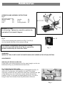
Euroboor EBS.500 is a portable band saw designed for cutting various metals like steel, iron, and copper. Equipped with a powerful 1010W motor, it delivers adjustable cutting speeds from 100 to 265 feet per minute. The EBS.500 features a durable 13 x 0.65 x 1440mm blade, enabling precise cuts in materials up to 5 inches thick. It offers manual cutting capability and includes a distance set bracket for repetitive cuts. Additionally, the saw can perform angle cuts from 0 to 60 degrees, making it versatile for various projects.
Euroboor EBS.500 is a portable band saw designed for cutting various metals like steel, iron, and copper. Equipped with a powerful 1010W motor, it delivers adjustable cutting speeds from 100 to 265 feet per minute. The EBS.500 features a durable 13 x 0.65 x 1440mm blade, enabling precise cuts in materials up to 5 inches thick. It offers manual cutting capability and includes a distance set bracket for repetitive cuts. Additionally, the saw can perform angle cuts from 0 to 60 degrees, making it versatile for various projects.


-
 1
1
-
 2
2
-
 3
3
-
 4
4
-
 5
5
-
 6
6
-
 7
7
-
 8
8
-
 9
9
-
 10
10
-
 11
11


Euroboor EBS.500 is a portable band saw designed for cutting various metals like steel, iron, and copper. Equipped with a powerful 1010W motor, it delivers adjustable cutting speeds from 100 to 265 feet per minute. The EBS.500 features a durable 13 x 0.65 x 1440mm blade, enabling precise cuts in materials up to 5 inches thick. It offers manual cutting capability and includes a distance set bracket for repetitive cuts. Additionally, the saw can perform angle cuts from 0 to 60 degrees, making it versatile for various projects.
Ask a question and I''ll find the answer in the document
Finding information in a document is now easier with AI