Page is loading ...

i-Control Disk Brake
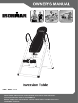
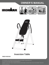
Inversion Table
5600.9-082517
The specifications of this product may vary from this photo and are subject to change without notice.
For more brand information, please visit www.IRONMAN.com
IRONMAN® and the "M-DOT" logo are registered trademarks of World Triathlon Corporation Official Product of the IRONMAN® TRIATHLON.
Used here by permission.


1
TABLE OF CONTENT
SERVICE------------------------------------------------------------------- 2
IMPORTANT SAFETY GUIDELINES------------------------------- 3
LABEL PLACEMENTS-------------------------------------------------- 6
OVERVIEW DRAWING------------------------------------------------- 7
PART LIST------------------------------------------------------------------ 9
HARDWARE LIST & TOOLS------------------------------------------ 11
ASSEMBLY----------------------------------------------------------------- 12
OPERATION AND ADJUSTMENTS--------------------------------- 21
STORAGE------------------------------------------------------------------ 28
WARRANTY---------------------------------------------------------------- 29
PARTS REQUEST FORM---------------------------------------------- 30

2
SERVICE
IMPORTANT: FOR NORTH AMERICA ONLY
For damaged or defective product, questions, replacement parts or any other service
support, please contact our customer service department by the below methods:
For The Best Service, please Email:
service@paradigmhw.com
Response Time: 1-2 Business Days
Emailing us with the information above will be the best method to receive a response during
peak business hours
Website:
www.paradigmhw.com
Toll-Free:
1-844-641-7922
(8:00 AM - 5:00 PM Pacific Standard Time, Daily)
Response time may vary via calling
Please have the following information ready when requesting for service:
Your name
Phone number
Model number
Serial number
Part number
Proof of Purchase
For damaged or defective product please contact our customer service before returning to
the store.
Paradigm Health & Wellness, Inc.
1189 Jellick Ave.
City of Industry, CA 91748, USA

3
IMPORTANT SAFETY GUIDELINES

4
IMPORTANT SAFETY GUIDELINES
Read all instructions before using the Inversion Table. When using an Inversion table, basic
precautions should always be followed, including the following:
WARNING - To reduce the risk of injury to persons:
1. Make sure your equipment is correctly assembled before you use it.
2. Be sure all screws, nuts, and bolts are tightened prior to use.
3. The equipment weighs more than 44lbs / 20kgs and should be assembled and moved by two or more people.
4. Only one person should use the equipment at a time.
5. Never operate this Equipment if it is damaged, If it is not working properly, has been dropped, or damaged. If a
problem is encountered contact Customer Service before using the equipment again.
6. Always use this equipment on a clear and level surface.
7. For household use only.
8. Do not use outdoors or near water.
9. Use the inversion table only for its intended use as described in this manual. Do not use attachments not
recommended by the manufacturer.
10. Do not wear loose clothing when using the equipment.
11. Keep all hands and feet away from any moving parts.
12. Never drop or insert any object into any opening.
13. Always wear shoes when using the inversion table.
14. Close supervision is necessary when the inversion table is used near children, or by or near invalids or
disabled persons.
15. Listen to your body. It is recommended that you rotate up and down slowly. Dizziness might occur if you
come up too fast.
16. If at any time you feel faint, light-headed, or dizziness while operating the equipment, stop exercising
immediately. You should also stop exercising if you are experiencing pain or any discomfort.
17. Wait 2 hours after eating before using the inversion table. If you start feeling nauseous, return to the
upright position slowly.
18. For any problems contact customer service. Servicing should be performed by an authorized service
representative. Our contact number is on the service page.
19. Warning: - Risk of Personal Injury - Consult with your personal physician to see if inversion equipment is
appropriate for you. This is especially important for people with pre-existing health problems. Do not use this
equipment without your physician's approval.
20. Warning: - Risk of Personal Injury – Do not allow children to use this machine.
21. Warning: - Risk of Personal Injury - Keep children under the age of 13 away from the machine
while in use.
22. Warning: - Risk of Personal Injury – Keep body parts, hair, loose clothing, and jewelry clear
of all moving parts.
23. Warning: - Risk of Personal Injury - Tilt-back slowly when inverting. Failure to comply could result
in serious bodily injury.
24. Warning: - Risk of Personal Injury - Do not attempt to service the unit yourself. Discontinue use
and contact customer service.
Warning: - To Reduce The Risk Of Personal Injury - Read And Understand All Read The Instructions
Before Using The Inversion Table.

5
The product weighs more than 44 lbs. It is heavily
recommended that at least 2 persons assemble.
IMPORTANT SAFETY GUIDELINES
Do not use this equipment if you have any of the following conditions or ailments:
Pregnancy
Extreme obesity
Middle ear infection
Hiatus hernia or Ventral hernia
Glaucoma, retinal detachment or conjunctivitis
Use of anticoagulants including Aspirin in high doses.
Spinal injury, Cerebral Sclerosis, or acutely swollen joints
Heart or circulatory disorders for which you are being treated
High blood pressure, Hypertension, Recent stroke or Transient Ischemic attack
Bone weaknesses including Osteoporosis, Unhealed fractures, Modular pins, or surgically implanted
orthopedic supports.
Do not exceed the maximum rated weight (load) and maximum rated
user height:
The Maximum Weight Capacity for this product is 275lbs/125kgs.
Retain this owner’s manual and keep the original purchase receipt
for future reference.
SAVE THESE GUIDELINES

6
LABEL PLACEMENTS

7
OVERVIEW DRAWING

8
OVERVIEW DRAWING

9
No.
Description
Qty
No.
Description
Qty
1
Front Frame
1
29
Handlebar
2
2
Cup Holder
1
30
Knob Ø45x3/8”x19L
1
3
Rear Frame
1
31
Steel Bracket
4
4
Cup Holder Rotation Cap
1
32
Bolt M6x30
1
5
Rectangle End Cap 50x25
5
33
Lock Mechanism
1
6
Front Rod
1
35
Foam Bed
1
7
Rubber Heel Holder
4
36
Handlebar Foam Grip
2
8
Adjustable Boom
1
37
Metal Sleeve
1
9
Rear Rod
1
38
Hex Socket Bolt M8x60
2
10
Bed Frame
1
39
Foot Bar
1
11
Foot bar End Cap
2
40
Hex Head Bolt M6x47
1
12
Right Pivot Arm
1
41
Square End Cap
□
38
2
13
Washer Ø20xØ8.5xt1.5
20
42
Spring Latch Ø4x32
1
14
Bolt M8x40
5
43
Bolt M8x12
2
15
Lock Nut M8 (Galvanize)
9
44
Height Scale
1
16
Lock Nut M6
2
45
Washer Ø24xØ8.5x2.0
2
17
Spring Knob
1
46
Hex Socket Bolt M8x20
6
18
Boom Spring Knob
1
47
Brake Bracket
1
19
Left Pivot Arm
1
48
Upper Plastic Cover
1
20
Rubber Pad
1
49
Rear Foot Cap
2
21
Right Brake Pad I
1
50
Bolt M6x25
1
22
Right Brake Pad I I
1
51
Bolt M6x15
4
23
Spring Ø10xØ1x110Lx85N
1
52
Lower Plastic Cover
1
24
Rotor Cover
1
53
Front Foot Cap
2
25
Round End Cap
Ø22x1.5
4
54
Pivot Arm Rotation Cap I
Ø60xØ19.5x18
2
26
Spring
Ø13xt2x(230)
1
55
Pivot Arm Rotation Cap II
Ø60xØ19.5x21
1
27
Washer Ø12xØ6.5x1.0
8
56
Hex Socket Bolt M8x50
2
28
Fixed Plate
1
57
Washer Ø9xØ4.3x0.3
4
PART LIST

10
No.
Description
Qty
No.
Description
Qty
58
Round Cap
1
65
Upper Bed Frame End Cap 50
1
59
Spring Washer Ø
8.1xØ12.3x2.1
1
66
Lower Bed Frame Bushing
2
60
Screw ST3.5x10
7
67
Rectangle End Cap 33.4
1
61
Brake Strap
2
68
Screw ST4.2x2
2
62
Nut Cap Ø27x13.5
4
69
Hex Socket Bolt M8x55
2
63
Bolt M4x20
1
70
Lock Handle Plastic Bar
1
64
Locking Pin Ø9.5x55
1
PART LIST

11
HARDWARE & TOOLS PACK

12
ASSEMBLY
The product weighs more than 44 lbs and should
be assembled and moved by two or more people.
Step 1
1A. Installing The Foot Caps
Attach two Front Foot Caps (53) to the feet of the Front Frame (1) and two Rear Foot Caps (49)
to the feet of the Rear Frame (3). Use a Bolt (51) and a Washer (27) to secure each foot cap to the
frames. Tighten the Bolts (51) with the Phillips Screwdriver provided.
1B. Setting Up The Frames
Align the holes at the top of the Front Frame (1) and the Rear Frame (3) and then secure the
frames together using two Hex Socket Bolts (38), four Washers (13), and two Lock Nuts (15).
Simultaneously tighten the bolt and nut with the 6mm Allen Wrench and the Hex Wrench.
Then insert the Locking Pin (64) into the holes at the joint of the Front Frames (1) and Rear
Frames (3). Attach a Nut Cap (62) onto both of the Lock Nuts (15).
Hardware:
Tools:
Hex Wrench 1 PC
6mm Allen Wrench 1 PC
Phillips Screwdriver 1 PC

13
ASSEMBLY
Step 2
2A. Installing The Bed Frame
Attach the Bed Frame (10) onto both the Right Pivot Arm (12) and the Left Pivot Arm (19) by
using two Lock Nuts (15), two Bolts (43), two Hex Socket Bolts (46), and two Washers (13).
Tighten the Bolts (43) with the 5mm Allen Wrench provided.
Simultaneously tighten the Hex Socket Bolts (46) and the Lock Nuts (15) with the 6mm Allen
Wrench and Hex Wrench provided.
Install the Knob (30) onto the Bed Frame (10).
Hardware:
Tools:
Hex Wrench
1 PC
6mm Allen Wrench
1 PC
5mm Allen Wrench
1 PC

14
ASSEMBLY
Step 3
3A. Installing the Lock Handle Plastic Bar
Slide the Lock Handle Plastic Bar (70) onto the Lock Mechanism (33). The “U shaped” end of
the Lock Handle Plastic Bar (70) MUST be facing the Brake Bracket (47) for correct installation.
See Fig. A.
Align the hole of the Lock Mechanism (33) with the hole in the middle of the Lock Handle Plastic
Bar (70) and insert one Bolt (63). See Fig. B. Tighten the Bolt (63) using the Phillips Screwdriver
provided.
Hardware:
Phillips Screwdriver
1 PC
Tool:
(63) Bolt
1 PC

15
Step 4
4A. Installing the Handlebars
Attach both of the Handlebars (29) onto the Rear Frame (3) with six Washers (13), two Lock Nuts
(15), two Hex Socket Bolts (69) and two Hex Socket Bolts (46).
Tighten the Hex Socket Bolts (46) with the 6mm Allen Wrench provided. Simultaneously tighten
the Hex Socket Bolts (69) and Lock Nuts (15) with the 6mm Allen Wrench and the Hex Wrench
provided.
Attach a Nut Cap (62) to each of the Lock Nuts (15).
Push in the Cup Holder (2) to the Cup Holder Rotation Cap (4) for an air tight seal.
Hardware:
ASSEMBLY
Tools:
6mm Allen Wrench
1PC
Hex Wrench
1PC

16
Step 5
5A. Installing The Rear Rod Onto The Adjustable Boom
Remove the Square End Cap (41) on the back of the Adjustable Boom (8), and set it aside for
Step 8. Slide the Rear Rod (9) through the large round hole on the side of the Adjustable Boom (8)
and align the rod’s middle hole with the smaller hole on the front of the Adjustable Boom (8).
Secure the rod onto the boom by using one Hex Head Bolt (40), two Washers (27) and one Lock
Nut (16). Simultaneously tighten the bolt and nut using the two Hex Wrenches provided. Make
sure the slots on the two ends of the Rear Rod (9) are facing forward.
Wrap two Rubber Heel Holders (7) with a Steel Bracket (31) each. Slide the Rubber Heel
Holders (7) onto the ends of the Rear Rod (9) until the lock teeth of the brackets lock in place with
slots on the rod.
Note: Make sure the lock teeth are wedged into the slots on the Rear Rod (9) as shown in the
Fig. A and B before using the inversion table.
Attach the Spring Knob (17) onto the Adjustable Boom (8) by turning it in a clockwise direction
until it is thoroughly tightened.
Hardware:
Tool:
Hex Wrench
2 PCS
ASSEMBLY

17
Step 6
6A. Installing The Foot Bar
Slide the Foot Bar (39) into the bottom shaft of the Adjustable Boom (8) and align any two holes
on the Foot Bar (39) with the two holes on the Adjustable Boom (8). Secure the Foot Bar (39) in
place using two Hex Socket Bolts (56), two Lock Nuts (15) and four Washers (13).
Simultaneously tighten the bolts and the nuts with the 6mm Allen Wrench and the Hex Wrench
provided.
Note: The extra holes on the Foot Bar (39) are for adjusting the distance between the heels and
the bar. The best set of holes to use will vary depending on the users’ personal preference. Once
the inversion table is completely assembled, try different positions for the Foot Bar (39) if the
first set of holes you try is not comfortable. Always thoroughly tighten the hardware before
testing different positions for the Foot Bar (39).
Hardware:
ASSEMBLY
Tools:
Hex Wrench
1 PC
6mm Allen Wrench
1 PC

18
Step 7
7A. Installing the Heel Holders To The Front Rod
Wrap two Rubber Heel Holders (7) with a Steel Bracket (31) each. Slide them onto the ends of
the Front Rod (6) until the lock teeth are wedged into the slot on the Front Rod (6) as shown
above.
Note: Make sure the lock teeth are wedged into the slots in the Front Rod (6) as shown in Fig.
A and B before using the inversion table.
ASSEMBLY
/