Toro TITAN Z5200 Zero-Turn-Radius Riding Mower User manual
- Category
- Lawnmowers
- Type
- User manual
This manual is also suitable for

Form No. 3358-273 Rev B
Titan™ Z4800 and Z5200
Model No. 74812 —Serial No. 270000001 and Up
Model No. 74814 —Serial No. 270000001 and Up
Register your product at www.Toro.com Original Instructions (EN)

2
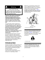
Warning
CALIFORNIA
Proposition 65 Warning
The engine exhaust from this product
contains chemicals known to the State of
California to cause cancer, birth defects,
or other reproductive harm.
Important: This engine is not equipped
with a spark arrester muffler. It is a
violation of California Public Resource
Code Section 4442 to use or operate the
engine on any forest-covered, brush-
covered, or grass-covered land. Other
states or federal areas may have similar
laws.
This spark ignition system complies with
Canadian ICES-002, ISO 14982, EN 55012.
The enclosed Engine Owner’s Manual is
supplied for information regarding the US
Environmental Protection Agency (EPA)
and the California Emission Control
Regulation of emission systems,
maintenance, and warranty. Replacements
may be ordered through the engine
manufacturer.
For models with stated engine horsepower,
the gross horsepower of the engine was
laboratory rated by the engine manufacturer
in accordance with SAE J1940. As configured
to meet safety, emission, and operating
requirements, the actual engine horsepower
on this class of lawn mower will be
significantly lower.
Introduction
Read this information carefully to learn how to
operate and maintain your product properly
and to avoid injury and product damage. You
are responsible for operating the product
properly and safely.
You may contact Toro directly at
www.Toro.com for product and accessory
information or help finding a dealer.
Whenever you need service, genuine Toro
parts, or additional information, contact an
Authorized Service Dealer or Toro Customer
Service and have the model and serial
numbers of your product ready. Figure 1
identifies the location of the model and serial
numbers on the product. Write the numbers
on the front cover.
Figure 1
Behind the seat
1. Model and serial number plate
This manual identifies potential hazards and
has safety messages identified by the safety
alert symbol (Figure 2), which signals a
hazard that may cause serious injury or death
if you do not follow the recommended
precautions.
Figure 2
1. Safety alert symbol.
This manual uses two other words to highlight
information. Important calls attention to
special mechanical information and Note
emphasizes general information worthy of
special attention.

3
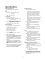
Specifications
Engine Specifications:
See Your Engine Owner’s Manual
RPM:
Full Speed: 3650 ± 100 (max) RPM
(No Load)
Idle: 1650 (min) RPM
Fuel System:
Capacity: 4.0 gal. (15.1L)
Type of Fuel: Regular unleaded gasoline,
87 octane or higher.
Fuel Filter: replaceable in-line BRIGGS &
STRATTON P/N 695666
Fuel Shut-Off Valve: in-line, 1/4 turn
Electrical System:
Charging System: Flywheel Alternator
Charging Capacity: 16 amps
Battery Type: BCI Group U1
Battery Voltage: 12 Volt
Polarity: Negative Ground
Fuses: 1-25 amp, 1-20 amp, 1-15amp
blade type
Safety Interlock System:
PTO must be disengaged, brake engaged,
and motion control levers out (neutral
lock) to start engine. (It is not necessary
for the operator to be in the seat to start the
engine.)
Operator must be in seat when PTO is
engaged, brake is disengaged, or motion
control levers are moved in or engine will
stop.
Engine will stop if either the left, the right, or
both levers are moved from neutral lock
position while brake is engaged.
Operator Controls
Steering and Motion Control:
Separate levers, on each side of the
console, control speed and direction of
travel of the respective drive wheels.
Steering is controlled by varying the
position of the levers relative to each
other.
Moving motion control levers outward (in
slots) locks the drive system in neutral.
Motion control levers are adjustable to
two heights.
PTO Switch: Engages electric clutch (to
drive belt) which engages mower
blades.
Parking Brake Lever: Engages parking
brake.
Deck Height Adjustment Pin: Sets cutting
height to desired position.
Deck Lift: Foot pedal that raises the deck.
Seat:
Type: Standard seat: high back, foam
padded with spring suspension.
Mounting: Hinged to tilt up for access to
battery and other components. Held in
tilted position with lanyard. Adjustable
fore and aft.
Armrests: Standard: foam padded flip-up
adjustable height armrests.
Seat Safety Switch: Incorporated into the
Safety Interlock System.
Hydrostatic Ground Drive System:
Hydrostatic Drive: Two Hydro Gear ZT2800
Integrated drive systems.
Hydraulic Oil: Use Mobil 1 15W-50 Synthetic
Motor Oil.
Speeds: All units:
0 – 7 mph (11.3 km/hr) forward.
0 – 5 mph (8.0 km/hr) reverse.
Drive wheel releases, located on left and
right sides of engine deck, allow machine to
be moved when the engine is not running
and brake is off.

4
Tires and Wheels
Drive Tires:
(48”) 20 x 9-8
(52”) 20 x 10-8
All 4-ply
Front Caster Tires:
Pneumatic, 10 x 4 smooth tread tires.
Cutting Deck
48” Deck: 48” (122 cm)
52” Deck: 52” (132 cm)
Discharge:
Side (Optional Mulch and/or Bag)
Blade Size:
48” Deck: 3 each - 16.25” blades
52” Deck: 3 each - 18” blades
Blade Spindles: solid steel spindles with no
maintenance bearings.
Deck Drive: Electric clutch mounted on
vertical engine shaft. Blades are driven by
one belt (w/self-tensioning idler) direct from
the engine.
Deck: Full floating deck.
Maximum turf protection is provided by
anti-scalp rollers: 3 rollers (48” & 52”)
Deck design allows for bagging, mulching or
side discharge.
Cutting Height Adjustment: a foot deck lift
lever is used to adjust the cutting height
from 1.5” (3.8 cm) to 4.5” (11.4 cm.) in 1/2”
(1.3 cm.) increments.
The cutting height adjustment handle has a
transport position and all adjustments can
be made while the operator remains seated.
Dimensions
Overall Width:
Without deck:
48” Deck: 45.5” (116 cm)
52” Deck: 47.0” (119 cm)
Deflector up:
48” Deck: 48.3” (122 cm)
52” Deck: 53.0” (135 cm)
Deflector down:
48” Deck: 59.4” (151 cm)
52” Deck: 64.2 (163 cm)
Overall Length:
48” Deck: 73.4” (186 cm)
52” Deck: 73.4” (186 cm)
Overall Height:
48” Deck: 42.2” (107 cm)
52” Deck: 42.2” (107 cm)
Tread Width: (center to center of tires,
widthwise)
Drive Wheels:
48” Deck: 42.2” (107 cm)
52” Deck: 42.2” (107 cm)
Front Casters:
48” Deck: 42.2” (107 cm)
52” Deck: 42.2” (107 cm)
Wheel Base: (center of caster tire to center of
drive tire)
48” Deck: 42.2” (107 cm)
52” Deck: 42.2” (107 cm)
Curb Weight:
48” Deck: 645 lbs (292.6 kg)
52” Deck: 660 lbs (299.4 kg)
Torque Requirements
Spindle Pulley Nuts: 45-55 ft-lbs (61-75 N-m)
Blade Mounting Bolt: 45-55 ft-lbs. (61-75N-m)
Anti-Scalp Roller Nuts: 27-33 ft-lbs. (37-45 N-m)
Engine Mounting Bolts: 27-33 ft-lbs. (37-45 N-m)
Wheel Lug Nuts: 70-90 ft-lbs. (95-122 N-m)
Clutch Mounting Bolt (secured with threadlocker):
50-55 ft-lbs. (68-75 N-m)

5
Contents
Introduction .................................................2
Specifications ..............................................3
Safety ..........................................................5
Safe Operating Practices .......................5
Toro Riding Mower Safety......................9
Slope Chart ..........................................10
Safety and Instructional Decals.............11
Product Overview .......................................15
Controls ................................................16
Operation ...................................................17
Think Safety First ..................................17
Recommended Gasoline.......................17
Checking the Engine Oil Level..............19
Starting the Engine................................19
Operating the Blades ............................20
Stopping the Engine..............................20
The Safety Interlock System .................20
Driving Forward or Backward................21
Stopping the Machine ...........................22
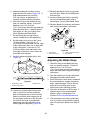
Tracking Adjustment .............................22
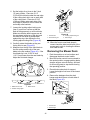
Adjusting the Height of Cut ...................23
Positioning the Seat ..............................23
Adjusting the Motion Control Levers .....23
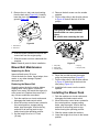
Pushing the Machine by Hand ..............24
Side Discharge......................................25
Operating Tips.......................................25
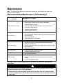
Maintenance
Recommended Maintenance
Schedule(s)...........................................27
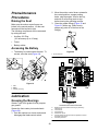
Premaintenance Procedures .....................28
Raising the Seat....................................28
Accessing the Battery ...........................28
Lubrication .................................................28
Greasing the Bearings ..........................28
Engine Maintenance ..................................29
Servicing the Air Cleaner ......................29
Servicing the Engine Oil .......................29
Checking the Hydraulic Oil Level.......... 31
Change the Hydraulic System Filter .....32
Servicing the Spark Plug ......................32
Cleaning the Blower Housing ...............33
Fuel System Maintenance .........................34
Replacing the Fuel Filter.......................34
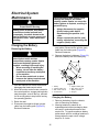
Electrical System Maintenance ..................35
Charging the Battery.............................35
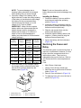
Servicing the Fuses and Relays ........... 36
Drive System Maintenance ........................ 37
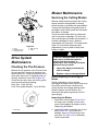
Checking the Tire Pressure .................. 37
Mower Maintenance ...................................37
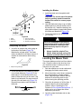
Servicing the Cutting Blades................. 37
Leveling the Mower Deck .....................39
Adjusting the Blade Slope.....................40
Removing the Mower Deck...................41
Mower Belt Maintenance ......................42
Installing the Mower Deck.....................42
Replacing the Discharge Deflector ...... 43
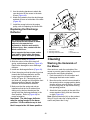
Cleaning .....................................................43
Washing the Underside of the Mower... 43
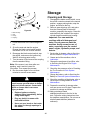
Storage .......................................................44
Cleaning and Storage ...........................44
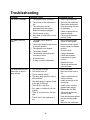
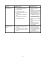
Troubleshooting..........................................46
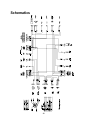
Schematics .................................................49

6
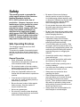
Safety
This machine meets or exceeds the
safety specifications of the American
National Standards Institute
B71.1-2003 in effect at the time of
production. However, improper use or
maintenance by the operator or owner
can result in injury. To reduce the
potential for injury, comply with these
safety instructions and always pay
attention to the safety alert symbol,
which means CAUTION, WARNING, or
DANGER-"personal safety instruction."
Failure to comply with the instruction
may result in personal injury or death.
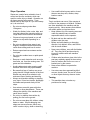
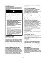
Safe Operating Practices
The following instructions are from ANSI
standard B71.1-2003.
This product is capable of amputating hands
and feet and throwing objects. Always follow
all safety instructions to avoid serious injury or
death.
General Operation
• Read, understand, and follow all
instructions in the operator’s manual and
on the machine before starting.
• Do not place hands or feet near rotating
parts or under the machine. Keep clear of
the discharge opening at all times.
• Allow only responsible adults who are
familiar with the instructions to operate the
machine.
• Clear the area of objects such as rocks,
toys, wire, etc., which could be picked up
and thrown by the blade.
• Be sure the area is clear of other people
before mowing. Stop the machine if
anyone enters the area.
• Never carry passengers.
• Do not mow in reverse unless absolutely
necessary. Always look down and behind
before and while backing up.
• Be aware of the mower discharge
direction and do not point it at anyone.
Avoid discharging material against a wall
or obstruction. Material may ricochet back
toward the operator. Stop the blades
when crossing gravel surfaces.
• Do not operate the mower without either
the entire grass collection system or the
discharge deflector in place.
• Be alert, slow down and use caution when
making turns. Look behind and to the side
before changing directions.
• Never leave a running machine
unattended. Always turn off blades,
engage parking brake, stop engine, and
remove key before dismounting.
• Turn off blades when not mowing. Stop
the engine, wait for all parts to come to a
complete stop, engage parking brake, and
remove key before cleaning the machine,
removing the grass or unclogging the
deflector.
• Operate the machine only in daylight or
good artificial light.
• Do not operate the machine while under
the influence of alcohol or drugs.
• Watch for traffic when operating near or
crossing roadways.
• Use extra care when loading or unloading
the machine into a trailer or truck.
• Always wear eye protection when
operating the mower.
• Data indicates that operators, age 60
years and above, are involved in a large
percentage of riding mower-related
injuries. These operators should evaluate
their ability to operate the riding mower
safely enough to protect themselves and
others from serious injury.
• Always follow the recommendations for
wheel weights or counterweights.

7
Slope Operation
Slopes are a major factor related to loss of
control and tip-over accidents, which can
result in severe injury or death. Operation on
all slopes requires extra caution. If you
cannot back up the slope or if you feel uneasy
on it, do not mow it.
• Do not mow slopes greater than
15 degrees.
• Watch for ditches, holes, rocks, dips, and
rises that change the operating angle, as
rough terrain could overturn the machine.
• Choose a low ground speed so you will
not have to stop while operating on a
slope.
• Do not mow slopes when grass is wet.
Slippery conditions reduce traction and
could cause sliding and loss of control.
• Reduce speed and use extreme caution
on slopes.
• Do not make sudden turns or rapid speed
changes.
• Remove or mark obstacles such as rocks,
tree limbs, etc. from the mowing area. Tall
grass can hide obstacles.
• Avoid sudden starts when mowing uphill
because the mower may tip backwards.
• Be aware that loss of traction may occur
going downhill. Weight transfer to the front
wheels may cause drive wheels to slip
and cause loss of braking and steering.
• Always avoid sudden starting or stopping
on a slope. If tires lose traction, disengage
the blades and proceed slowly off the
slope.
• Use extreme care with grass collection
systems or other attachments. These can
change the stability of the machine and
cause loss of control.
• Do not try to stabilize the machine by
putting your foot on the ground.
• Do not mow near drop-offs, ditches, steep
banks or water. Wheels dropping over
edges can cause rollovers, which may
result in serious injury, death or drowning.
• Use a walk behind mower and/or a hand
trimmer near drop-offs, ditches, steep
banks or water.
Children
Tragic accidents can occur if the operator is
not alert to the presence of children. Children
are often attracted to the machine and the
mowing activity. Never assume that children
will remain where you last saw them.
• Keep children out of the mowing area and
under the watchful care of another
responsible adult, not the operator.
• Be alert and turn the machine off if
children enter the area.
• Before and while backing or changing
direction, look behind, down, and side-to-
side for small children.
• Never carry children, even with the blades
off. They may fall off and be seriously
injured or interfere with safe machine
operation.
• Children who have been given rides in the
past may suddenly appear in the mowing
area for another ride and be run over or
backed over by the mower.
• Never allow children to operate the
machine.
• Use extra care when approaching blind
corners, shrubs, trees, the end of a fence
or other objects that may obscure vision.
Towing
• This machine does not make any
provisions for towing.

8
Service
Safe Handling of Gasoline:
To avoid personal injury or property damage,
use extra care when handling gasoline and
other fuels. They are flammable and the
vapors are explosive.
• Extinguish all cigarettes, cigars, pipes and
other sources of ignition.
• Use only an approved container.
• Never remove the gas cap or add fuel
when the engine is running. Allow the
engine to cool before refueling.
• Never refuel the machine indoors.
• Never store the machine or fuel container
inside where there is an open flame, such
as near a water heater or furnace.
• Never fill containers inside a vehicle or on
a truck or trailer with a plastic liner.
Always place containers on the ground
away from your vehicle before filling.
• Remove gas-powered equipment from the
truck or trailer and refuel it on the ground.
If this is not possible, then refuel such
equipment with a portable container,
rather than from a gasoline dispenser
nozzle.
• Keep the nozzle in contact with the rim of
the fuel tank or container opening at all
times until the fueling is complete. Do not
use a nozzle lock-open device.
• If fuel is spilled on clothing, change
clothing immediately.
• Never overfill the fuel tank. Replace gas
cap and tighten securely.
General Service:
• Never run a machine inside a closed area.
• Keep nuts and bolts tight, especially the
blade attachment bolts. Keep equipment
in good condition.
• Never tamper with safety devices. Check
their proper operation regularly.
• Keep the machine free of grass, leaves, or
other debris build-up. Clean up oil or fuel
spillage and fuel soaked debris. Allow the
machine to cool before storing.
• Stop and inspect the equipment if you
strike an object. Repair, if necessary,
before restarting.
• Never make any adjustments or repairs
with the engine running.
• Grass collection system components are
subject to wear, damage and
deterioration, which could expose moving
parts or allow objects to be thrown.
Frequently check components and
replace with manufacturers’
recommended parts, when necessary.
• Mower blades are sharp and can cut.
Wrap the blades or wear gloves, and use
extra caution when servicing them.
• Check for proper brake operation
frequently. Adjust and service as
required.
• Maintain or replace safety and instruction
decals as necessary.
• Use only genuine Toro replacement parts
to ensure that original standards are
maintained.

9
Toro Riding Mower Safety
The following list contains safety information
specific to Toro products or other safety
information that you must know that is not
included in the ANSI standards.
• Engine exhaust contains carbon
monoxide, which is an odorless, deadly
poison that can kill you. Do not run
engine indoors or in an enclosed area.
• Stop the engine, wait for all moving
parts to stop, engage parking brake,
disconnect spark plug wire(s) and
remove key before performing any
service, repairs, maintenance or
adjustments.
• Keep hands, feet, hair, and loose
clothing away from attachment
discharge area, underside of mower and
any moving parts while engine is
running.
• Do not touch equipment or attachment
parts which may be hot from operation.
Allow to cool before attempting to
maintain, adjust or service.
• Battery acid is poisonous and can cause
burns. Avoid contact with skin, eyes, and
clothing. Protect your face, eyes, and
clothing when working with a battery.
• Battery gases can explode. Keep
cigarettes, sparks and flames away from
battery.
• Use only Toro approved attachments.
Warranty may be voided if used with
unapproved attachments.
• If loading the machine onto a trailer or
truck, use a single, full-width ramp only.
The ramp angle should not exceed
15 degrees.
Note: The left and right sides of the machine
are determined while sitting in the seat in the
normal operating position.

10
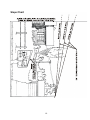
Slope Chart

11
1
2
2
1
3
G1101
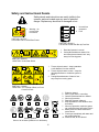
Safety and Instructional Decals
Safety decals and instructions are easily visible to the
operator and are located near any area of potential
danger. Replace any decal that is damaged or lost.
Battery Symbols
Some or all of these symbols are on the battery.
PART NO. 106-5517
LOCATION: On LH & RH Rear Frame
1
1. Warning – do
not touch the
hot surface.
1
2
2
3
1. Explosion hazard
2. No fire, open flame, or smoking.
3. Caustic liquid/chemical burn hazard.
4. Wear eye protection.
5. Read the Operator’s Manual.
6. Keep bystanders a safe distance from
the battery.
7. Wear eye protection; explosive gases
can cause blindness and other injuries.
8. Battery acid can cause blindness or
severe burns.
9. Flush eyes immediately with water and
get medical help fast.
10. Contains lead; do not discard.
PART NO. 109-6210
LOCATION: Under Seat Shield
1. Read the Operator’s manual
2. Cutting/dismemberment hazard, fan
and entanglement hazard, belt– stay
away from moving parts.
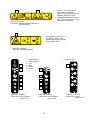
1. Thrown objects hazard – keep bystanders
a safe distance from the machine.
2. Thrown objects hazard, mower – keep the
discharge deflector or collection system in
place.
3. Cutting/dismemberment of hand or foot –
stay away from moving parts.
PART NO. 110-6691
LOCATION: On Top Side of Deck, on Front
Corners of Deck
PART NO. 109-6011
LOCATION: Inside Seat Box by Fuse Box
1. Unused fuse
receptacle
2. Fuse
2
1
4
6
7
8
9
10
5

12
1
3
5
6
4
2
3
4
5
6
2
PART NO. 93-7009
LOCATION: Behind Discharge Deflector on
Deck Side Plate
PART NO. 109-6459
LOCATION: Under Belt Shields
1. Entanglement hazard, belt – do
not open or remove safety
shields while engine is running,
keep shields in place.
1
1
2
1. Warning – do not operate the
mower with the discharge
deflector up or removed; keep the
discharge deflector in place.
2. Cutting/dismemberment hazard of
hand or foot, mower blade – stay
away from moving parts.
PART NO. 99-8936
LOCATION: Near RH Motion
Control Lever
PART NO. 109-6009
LOCATION: Near LH Motion
Control Lever
1. Parking Brake
2. Machine Speed
3. Fast
4. Slow
5. Neutral
6. Reverse
PART NO. 109-6010
LOCATION: On Cut
Height Frame
1. Height of cut
1

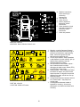
13
A
B
B
C
F
E
D
1
3
4
2
6
5
7
1. Warning—read the Operator’s Manual.
2. Read the instructions before servicing or
performing maintenance; apply parking
brake, remove the ignition key and
disconnect the spark plug wire.
3. Thrown object hazard – keep bystanders
a safe distance from the machine, pick up
debris before operating, keep the
discharge deflector in place.
4. Loss of traction/control hazard, slopes –
loss of traction/control on slope,
disengage the blade control switch (PTO),
proceed off the slope slowly.
5. Tipping hazard – avoid sudden and sharp
turns while on slopes, only mow across
slopes less than 15 degrees, keep a safe
distance from water, and do not mow up
and down slopes.
6. Cutting/dismemberment hazard of hand or
foot, mower blade – stay away from
moving parts.
7. Crushing/dismemberment hazard of
bystanders, reversing;– do not carry
passengers, look behind and down when
reversing.
PART NO. 109-6013
LOCATION: Middle of Footrest
PART NO. 109-6016
LOCATION: Near LH Motion Control Lever
A. Read the instructions
before servicing or
performing
maintenance.
B. Time interval.
C. Check oil level.
D. Refer to Operator’s
Manual for grease
instructions.
E. Check hydraulic oil level
and refer to Operator’s
manual for further
instructions.
F. Check tire pressure.

14
109-6029
1
2
3
2
1
3
2
1
3
4
5
6
7
8
9
1. Read the Operator’s
Manual.
2. Rotate the drive release
knob to loosen, slide the
knob, and tighten.
3. Push the machine.
PART NO. 109-6008
LOCATION: Next to Drive
Release
1. Engine – stop
2. Engine – run
3. Engine – start
4. Power take-off
(PTO), Blade control
switch.
5. Read Operator’s
Manual
6. Throttle - fast
7. Choke – on
8. Throttle – slow
9. Choke – off
PART NO. 109-6029
LOCATION: On Control Panel
PART NO. 109-6014
LOCATION: RH Side of
Seat Box
PART NO. 109-6035
LOCATION: Left Rear Edge of Deck
1. Read Operator’s
Manual.
2. Remove the ignition
key and read the
instructions before
servicing or
performing
maintenance.
3. Height of cut.
PART NO. 109-6036
LOCATION: Top of Deck Near Washout Port
TRACTION DRIVE
BELT ROUTING
DECK DRIVE
BELT ROUTING
LOCATION: Blades

15
Product Overview
Figure 3
1. Operator seat
2. Front caster wheel
3. Anti-scalp roller
4. Washout fitting
5. Park brake
6. Rear drive wheel
7. Gas tank cap
Figure 4
1. Motion control levers
2. Engine
3. Control panel
4. Discharge deflector
5. Height of cut adjustment
6. Height of cut foot lever
7. Footrest

16
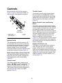
Controls
Become familiar with all of the controls in
Figure 3, Figure 4, and Figure 5 before you
start the engine and operate the machine.
Figure 5
Control Panel
1. Ignition switch 3. Throttle
2. Blade control switch 4. Choke
(power take-off)
Ignition Switch
The ignition switch has three positions, Off,
Run and Start. The key will turn to Start and
move back to Run upon release. Turning the
key to the Off position will stop the engine;
however, always remove the key when
leaving the machine to prevent someone from
accidentally starting the engine (Figure 5).
Blade Control Switch (Power Take-Off)
The blade control switch, represented by a
power take-off (PTO) symbol, engages and
disengages power to the mower blades
(Figure 5).
Choke Control
The choke is used to aid in starting a cold
engine. DO NOT run a warm engine with the
choke in the “ON” position. Moving the
choke lever forward will put the choke in the
“ON” position and moving the choke lever to
the rear will put the choke in the “OFF”
position (Figure 5).
Throttle Control
The throttle is used to control engine speed.
Moving throttle lever forward will increase
engine speed and moving throttle lever to the
rear will decrease engine speed. Moving the
throttle forward into the detent is full throttle
(Figure 5).
Motion Control Levers and Parking
Brake
The motion control levers are speed sensitive
controls of independent wheel motors. Moving
a lever forward or backward turns the wheel on
the same side forward or in reverse; wheel
speed is proportional to the amount the lever is
moved. Moving the control levers outward from
the center position locks them in the neutral
position. Engaging the parking brake lever
allows the operator to exit the machine
(Figure 13). Always position the motion control
levers into the neutral position and engage the
park brake lever when you stop the machine or
leave it unattended.
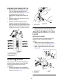
Height-of-Cut Foot Lever
The height of cut lever allows the operator to
lower and raise the deck from the seated
position. When the lever is moved forward,
away from the operator the deck is raised from
the ground and when moved back, towards the
operator it is lowered toward the ground. Only
adjust the height of cut while machine is not
moving (Figure 14).

17
Operation
Note: The left and right sides of the machine
are determined while sitting in the seat in the
normal operating position.
Think Safety First
Please carefully read all of the safety
instructions and decals in the safety section.
Knowing this information could help you, your
family, pets or bystanders avoid injury.
Mowing on wet grass or steep slopes
can cause sliding and loss of control.
Wheels dropping over edges can
cause rollovers, which may result in
serious injury, death or drowning.
To avoid loss of control and possibility
of rollover:
• Do not mow near drop-offs or near
water.
• Do not mow slopes greater than
15 degrees.
• Reduce speed and use extreme
caution on slopes.
• Avoid sudden turns or rapid speed
changes.
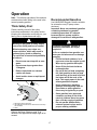
Figure 6
1. Safe Zone-use the Titan here.
2. Use walk behind mower and/or hand trimmer near drop-
offs and water.
3. Water
Refer to the Slope Chart on page 10 to
determine the approximate slope angle to be
mowed.
Recommended Gasoline
Use UNLEADED Regular Gasoline suitable
for automotive use (87 pump octane
minimum).
Important: Never use methanol, gasoline
containing methanol, or gasohol
containing more than 10% ethanol
because the fuel system could be
damaged. Do not mix oil with gasoline.
In certain conditions, gasoline is
extremely flammable and highly
explosive.
A fire or explosion from gasoline can
burn you and others and can damage
property.
• Fill the fuel tank outdoors, in an
open area, when the engine is cold.
Wipe up any gasoline that spills.
• Never fill the fuel tank inside an
enclosed trailer.
• Do not fill the fuel tank completely
full. Add gasoline to the fuel tank
until the body of the tank is full but
fuel does not fill the neck of the
tank. This empty space in the tank
allows gasoline to expand.
• Never smoke when handling
gasoline, and stay away from an
open flame or where gasoline
fumes may be ignited by a spark.
• Store gasoline in an approved
container and keep it out of the
reach of children. Never buy more
than a 30-day supply of gasoline.
• Do not operate without entire
exhaust system in place and in
proper working condition.

18
In certain conditions during fueling,
static electricity can be released
causing a spark which can ignite the
gasoline vapors.
A fire or explosion from gasoline can
burn you and others and can damage
property.
• Always place gasoline containers
on the ground away from your
vehicle before filling.
• Do not fill gasoline containers
inside a vehicle or on a truck or
trailer bed because interior
carpets or plastic truck bed liners
may insulate the container and
slow the loss of any static charge.
• When practical, remove gas-
powered equipment from the
truck or trailer and refuel the
equipment with its wheels on the
ground.
• If this is not possible, then refuel
such equipment on a truck or
trailer from a portable container,
rather than from a gasoline
dispenser nozzle.
• If a gasoline dispenser nozzle must
be used, keep the nozzle in contact
with the rim of the fuel tank or
container opening at all times until
fueling is complete.
Gasoline is harmful or fatal if
swallowed.
Long-term exposure to vapors can
cause serious injury and illness.
• Avoid prolonged breathing of
vapors.
• Keep face away from nozzle and
gas tank or conditioner opening.
• Keep gas away from eyes and skin.
Using Stabilizer/Conditioner
Use a fuel stabilizer/conditioner in the
machine to provide the following benefits:
• Keeps gasoline fresh during storage of 30
days or less. For longer storage it is
recommended that the fuel tank be
drained.
• Cleans the engine while it runs
• Eliminates gum-like varnish buildup in the
fuel system, which causes hard starting
Add the correct amount of gas
stabilizer/conditioner to the gas.
Note: A fuel stabilizer/conditioner is most
effective when mixed with fresh gasoline. To
minimize the chance of varnish deposits in
the fuel system, use fuel stabilizer at all times.
Gasoline/Alcohol blends
Gasohol (up to 10 percent ethyl alcohol, 90
percent unleaded gasoline by volume) is
approved for fuel use by the engine
manufacturer. Other gasoline/alcohol blends
are not approved.
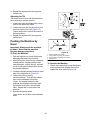
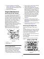
Filling the Fuel Tank
1. Shut the engine off and set the motion
controls to the neutral position and
engage parking brake.
2. Clean around the fuel tank cap and
remove the cap.
3. Add unleaded regular gasoline until the
body of the tank is full but fuel does not fill
the neck of the tank (Figure 7). This

19
space in the neck of the tank allows
gasoline to expand. Do not fill the fuel
tank completely full.
4. Install the fuel tank cap securely. Wipe up
any gasoline that may have spilled.
Figure 7
1. Gas tank opening
2. Fill to here, approximately
3. Gas tank body
Checking the Engine Oil
Level
Before you start the engine and use the
machine, check the oil level in the engine
crankcase; refer to Checking the Oil Level in
Engine Maintenance.
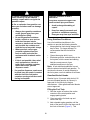
Starting the Engine
1. Sit down on the seat and move the motion
controls outward to the neutral position
and engage the parking brake.
2. Disengage the blades by moving the
blade control switch to Off (Figure 8).
Figure 8
1. Control panel
2. Blade control switch—Off position
3. Move the throttle lever to midway and the
choke lever forward before starting a cold
engine (Figure 9).
Note: A warm or hot engine may not require
choking.
Figure 9
1. Control panel 4. Choke – off
2. Throttle – fast 5. Choke – on
3. Throttle – slow
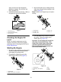
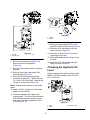
4. Turn the ignition key to Start to energize
the starter. When the engine starts,
release the key (Figure 10).
Important: Do not engage the starter for
more than 5 seconds at a time. If the
engine fails to start, allow a 60 second
cool-down period between attempts.
Failure to follow these instructions can
burn out the starter motor.
Figure 10
1. Control panel 4. Run
2. Ignition key—start position 5. Start
3. Off 6. Choke

20
5. If the engine stalls or hesitates, move the
choke lever partially forward for a few
seconds. (Figure 10).
Operating the Blades
The blade control switch, represented by a
power take-off (PTO) symbol, engages and
disengages power to the mower blades. This
switch controls power to any attachments that
draw power from the engine, including the
mower deck and cutting blades.
Engaging the Blades
1. Release pressure on the motion control
levers and place the machine in neutral.
2. Pull out on the blade control switch to On
to engage the blades (Figure 11).
3. Move throttle to full forward position
before mowing.
Figure 11
1. Control panel
2. Blade control switch—On position
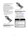
Disengaging the Blades
Push the blade control switch to Off to
disengage the blades (Figure 12).
Figure 12
1. Control panel
2. Blade control switch—Off
Stopping the Engine
1. Disengage the blades by moving the
blade control switch to Off (Figure 12).
2. Turn the ignition key to Off (Figure 10).
3. Pull the wire off of the spark plug(s) to
prevent the possibility of someone
accidentally starting the machine before
transporting or storing the machine.
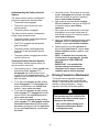
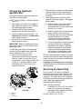
The Safety Interlock System
If safety interlock switches are
disconnected or damaged the machine
could operate unexpectedly causing
personal injury.
• Do not tamper with the interlock
switches.
• Check the operation of the interlock
switches daily and replace any
damaged switches before operating
the machine.
Page is loading ...
Page is loading ...
Page is loading ...
Page is loading ...
Page is loading ...
Page is loading ...
Page is loading ...
Page is loading ...
Page is loading ...
Page is loading ...
Page is loading ...
Page is loading ...
Page is loading ...
Page is loading ...
Page is loading ...
Page is loading ...
Page is loading ...
Page is loading ...
Page is loading ...
Page is loading ...
Page is loading ...
Page is loading ...
Page is loading ...
Page is loading ...
Page is loading ...
Page is loading ...
Page is loading ...
Page is loading ...
Page is loading ...
Page is loading ...
Page is loading ...
Page is loading ...
-
 1
1
-
 2
2
-
 3
3
-
 4
4
-
 5
5
-
 6
6
-
 7
7
-
 8
8
-
 9
9
-
 10
10
-
 11
11
-
 12
12
-
 13
13
-
 14
14
-
 15
15
-
 16
16
-
 17
17
-
 18
18
-
 19
19
-
 20
20
-
 21
21
-
 22
22
-
 23
23
-
 24
24
-
 25
25
-
 26
26
-
 27
27
-
 28
28
-
 29
29
-
 30
30
-
 31
31
-
 32
32
-
 33
33
-
 34
34
-
 35
35
-
 36
36
-
 37
37
-
 38
38
-
 39
39
-
 40
40
-
 41
41
-
 42
42
-
 43
43
-
 44
44
-
 45
45
-
 46
46
-
 47
47
-
 48
48
-
 49
49
-
 50
50
-
 51
51
-
 52
52


Toro TITAN Z5200 Zero-Turn-Radius Riding Mower User manual
- Category
- Lawnmowers
- Type
- User manual
- This manual is also suitable for
Ask a question and I''ll find the answer in the document
Finding information in a document is now easier with AI
Related papers
-
Toro Z286E Z Master, With 72" SFS Side Discharge Mower User manual
-
Toro GrandStand Mower, With 122cm TURBO FORCE Cutting Unit User manual
-
Toro TimeCutter Z4200 Riding Mower User manual
-
-
-
-
-
-
-
Toro Z334 Z Master, With 34in 7-Gauge Side Discharge Mower User manual
Other documents
-
Encore ER32FS600VL ER36FS600VL Rage Owner's manual
-
-
 Exmark Quest QST22BE482 User manual
-
 Tilton Yard Shark YSH2051Z User manual
-
 Alroh RESIDENTIAL CYLINDER MOWER Owner's manual
-
 M.E.Y. Equipment RESIDENTIAL CYLINDER MOWER User manual
-
MyBinding Challenge Titan 200 Tech User manual
-
-
-


