9
CAUTION: The
manufacturer’s warranty
does not cover any damage
or defect caused by
installation, attachment
or use of any type of
energy saving or other
unapproved devices (other
than those authorized by
the manufacturer) into,
onto or in conjunction
with the water heater.
The use of unauthorized
energy saving devices may
shorten the life of the water
heater and may endanger
life and property. The
manufacturer disclaims any
responsibility for such loss
or injury resulting from the
use of such unauthorized
devices.
Electrical Connections - Field Conversions
For installation to a single branch
circuit in either single phase or
three phase simultaneous or non-
simultaneous operation, the water
heater must be converted in the field
according to below instructions.
Single Phase
Simultaenous
To install the water heater as a single
phase simultaneous operation to a
single branch circuit, remove the
black/white wire from terminal Tl
and the red/black wire from terminal
T2. The black/white wire is field
connected with the yellow/black wire
to terminal Ll. The red/black wire is
field connected with blue/white wire
to terminal L2. The branch circuit
is connected to terminals Ll and L2,
and it must be sized according to the
total rating of the water heater (upper
element rating+ lower element rating).
Single Phase Non-
Simultaneous
To install the water heater as a single
phase non-simultaneous operation to
a single branch circuit, remove the
black/white wire from terminal Tl
and the red/black wire from terminal
T2. The black/white wire is field
connected with brown/white wire to
terminal TM. The red/black wire is
field connected with blue/white wire
to terminal L2. The branch circuit is
connected to terminals L1 and L2, and
it must be sized according to either
the upper element rating or the lower
element rating, whichever is greater. If
they are equal, size the branch circuit
according to the lower element rating.
Single Phase Non-
Simultaneous with Off-
Peak Meter or Timer
To install the water heater as a single
phase non-simultaneous operation with
off-peak meter or timer, remove the
red/black wire from terminal T2. The
red/black wire is field connected with
blue/white wire to terminal L2. The
off-peak meter or timer is connected
to terminals TM and Tl. The branch
circuit is connected to terminal L1 and
L2, and it must be sized according to
either the upper element or the lower
element rating, whichever is greater. If
they are equal, size the branch circuit
according to the lower element rating.
Single Phase Non-
Simultaneous with Off-
Peak Meter or Timer
(3-wire)
To install the water heater as a single
phase non-simultaneous operation
with off-peak meter or timer (3-wire),
remove the black/white wire from
terminal Tl. The black/white wire is
field connected with brown/white wire
to terminal TM. The off-peak meter
or timer is connected to terminal T2.
The branch circuit is connected to
terminals L1 and L2, and it must be
sized according to either the upper
element or the lower element rating,
whichever is greater. If they are equal,
size the branch circuit according to the
lower element rating.
Three Phase Simultaneous
To install the water heater as a three
phase simultaneous operation, remove
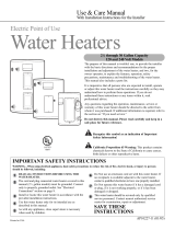
Potential Field Conversions
Base Model
Single Phase
Simultaneous
Single Phase Non-
Simultaneous
Single Phase Non-
Simultaneous with
Off- Peak Meter
or Timer
Single Phase Non-
Simultaneous with
Off- Peak Meter or
Timer (3-wire)
Three Phase
Simultaneous
Three Phase Non-
Simultaneous
ELDS30 YES YES YES YES YES YES
ELDS40 YES YES YES YES YES YES
ELDS52 YES YES YES YES YES YES
ELD30 YES YES YES YES YES YES
ELD40 YES YES YES YES YES YES
ELD52 YES YES YES YES YES YES
ELD66 YES YES YES YES YES YES
ELD80 YES YES YES YES YES YES
ELD120 YES YES YES YES YES YES
Installing the water heater.