Page is loading ...

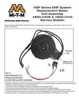
HSP Series EMF System
Ignition Coil Assembly
#850-0414 & #850-0413
Service Bulletin
“This Side
Out”
When ignition coil (A) is mounted correctly you can read “this side out.”
Coil to magnet gap = .010 inch.
Ref. #1
#850-0414 Ignition Coil
For HSP-2003 and HSP-2403 Models
A
Ignition Coil
When installing the 850-0414 ignition coil (Ref. #1) or 850-0413 ignition coil (Ref . #2) to the EMF System you will
need to make sure the coil is installed properly. If the mounting ange is rotated 180 degrees from what is shown
in the picture below no voltage will be present. Thus causing no spark.

CYL. SIDE
facing out
When the ignition coil (A) is installed correctly, the wording “this side out” will actually be facing in towards the
machine. The front side of the coil, which will be facing out towards you, will read 'CYL. SIDE'.
Coil to magnet gap = .010 inch.
When installing the coil remove the complete EMF and see additional instructions for drilling 2
1
⁄8" hole for coil wires
to exit the blower housing.
Ignition Coil
A
Ref. #3
#850-0413 Ignition Coil
For HSP-3003, HSP-3004
and HSP-3504 Models
37-1341/Mi1802/062018
Mi-T-M Corporation
50 Mi-T-M Drive, P.O. Box 50
Peosta, IA 52068
800-553-9053 · 563-556-1235 fax
www.mitm.com · [email protected]
/