
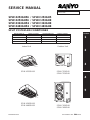
INDOOR MODEL No. PRODUCT CODE No. OUTDOOR MODEL No. PRODUCT CODE No.
SPW-X253GH56 854 011 35 SPW-C253GH5 854 012 18
SPW-X253GH56 854 011 35 SPW-C253GH8 854 012 19
SPW-X363GH56 854 011 36 SPW-C363GH8 854 012 20
SPW-X483GH56 854 011 37 SPW-C483GH8 854 012 21
FILE NO.
SERVICE MANUAL
1
2
3
4
5
Section
85464849133001 REFERENCE NO. SM830033
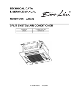
SPW-X253GH56 ⁄ SPW-C253GH5
SPW-X253GH56 ⁄ SPW-C253GH8
SPW-X363GH56 ⁄ SPW-C363GH8
SPW-X483GH56 ⁄ SPW-C483GH8
SPLIT SYSTEM AIR CONDITIONER
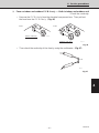
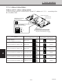
SPW-C253GH5
SPW-C253GH8
SPW-X253GH56
0407_X_S
SPW-X363GH56
SPW-X483GH56
SPW-C363GH8
SPW-C483GH8
Indoor Unit Outdoor Unit
0406_X_S
0408_C_S
0409_C_S

– 3 –
SM830033
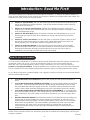
WHO SHOULD USE THIS MANUAL
This service manual is made to assist the service technician apply his knowledge and
training to this model air conditioner. This manual is written both for experienced service
persons and those who are new to air conditioning service. To help those with less
experience or who are new to this kind of unit we have included more explanations of
basic procedures in simple language than is usual in some service manuals. The experi-
enced technician will of course find he knows many of these things already and can go
directly to the procedures and information he needs; the less experienced technician will
better understand what to do even before he arrives on the job, and therefore be better
able to work by himself as well as assist the more experienced technician.
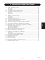
TABLE OF CONTENTS
1. SPECIFICATIONS....................................................................................................... 7
1-1 Unit Specifications .............................................................................................. 8
1-2 Major Component Specifications ...................................................................... 12
(A)Indoor Unit .................................................................................................... 12
(B)Outdoor Unit ................................................................................................ 14
1-3 Other Component Specifications ...................................................................... 17
1-4 Dimensional Data................................................................................................19
(A)Indoor Unit .....................................................................................................19
(B)Outdoor Unit ..................................................................................................21
1-5 Refrigerant Flow Diagram ...................................................................................23
1-6 Operating Range.................................................................................................24
2. PROCESSES AND FUNCTIONS ...........................................................................25
2-1 Room Temperature Control ................................................................................26
(A) Cooling..........................................................................................................26
(B) Heating..........................................................................................................27
2-2 Cold Draft Prevention (Heating Cycle) ................................................................28
2-3 Automatic Fan Speed (Indoor Unit).....................................................................29
(A) Cooling..........................................................................................................29
(B) Heating..........................................................................................................29
2-4 Outdoor Fan Speed Control................................................................................30
(A) Cooling..........................................................................................................30
(B) Heating..........................................................................................................30
2-5 Freeze Prevention (Cooling) ...............................................................................31
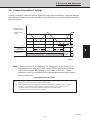
2-6 Condensing Temperature Control (Cooling) ...................................................... 32
2-7 Overload Protection (Heating).............................................................................33
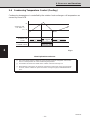
2-8 Discharge Temperature Control (Cooling and Heating)..................................... 34
2-9 Auto. Mode for Automatic Heating/Cooling Switching........................................ 34

– 4 –
SM830033
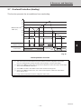
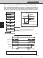
2-10 Defrosting Control, Outdoor Heat Exchanger Coil (Heating).............................. 36
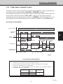
2-11 4-Way Valve, Solenoid Control ...........................................................................37
(A) Normal Control Mode ....................................................................................37
(B) AUTO Control Mode......................................................................................38
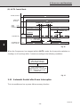
2-12 Automatic Restart after Power Interruption ........................................................ 38
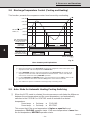
2-13 Electronic Refrigerant Control Valve...................................................................39
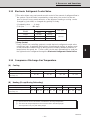
2-14 Compressor Discharge Gas Temperature ......................................................... 39
(A) Cooling..........................................................................................................39
(B) Heating (Except During Defrosting)...............................................................39
2-15 Compressor Current Detection Circuit ................................................................40
2-16 Dehumidifying Operation ....................................................................................41
2-17 Auto-flap Control .................................................................................................42
2-18 Drain Pump Control ............................................................................................42
2-19 Electronic Refrigerant Control Valve Control ..................................................... 43
2-20 Voltage Detection Control ...................................................................................44
3. ELECTRICAL DATA ..................................................................................................45
3-1 Indoor Unit (Electric Wiring Diagram, Schematic Diagram) ............................... 46
3-2 Outdoor Unit (Electric Wiring Diagram, Schematic Diagram)............................. 48
4. SERVICE PROCEDURES...........................................................................................57
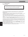
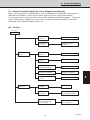
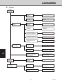
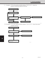
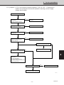
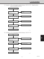
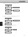
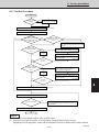
4-1 Troubleshooting ..................................................................................................58
4-2 Checking the Electrical Components ..................................................................92
5. INSTRUCTION MANUAL.........................................................................................107

– 5 –
SM830033
WHAT IS IN THIS MANUAL
Introduction:
Read Me First!
This manual will help you understand and service the air conditioner. To help you find the information you
need, we have divided it into 5 main sections. Each section is divided into chapters with charts, tables and
explanations to help you find and repair problems.
❑ Section 1: Specifications, tells you about the physical and electrical make up of the unit, as
well as its heating and cooling capacities. Look in this section to find the correct values for
components and functions.
❑ Section 2: Processes and Functions, explains each different part of the cooling and
heating cycle, and how each control function reacts to changing conditions to keep the room
at the set temperature range.
❑ Section 3: Electrical Data, which has fold-out schematic and wiring diagrams so you can
find the parts you need to check when something is wrong, and see how they should be
connected.
❑ Section 4: Service Procedures, has two main parts, a
diagnostic
chapter to help you find
the specific component to replace or adjust, and a chapter with specific procedures and
values to guide you in checking the electrical components in the unit.
❑ Section 5: Instruction Manual, is the same manual the user will have, and it contains
general information about how to set and use the features of this particular air conditioner.
Knowing this information will help you tell the owner how to use and care for this air
conditioner, and also help you install and set the unit correctly.
HOW TO USE THIS MANUAL
You can use this manual both as a
reference
to find specific information about the
capacity, functions and
construction of this unit, and as a source of information to help you set up and maintain the unit.
When this unit is not working properly, and the cause is not known, you can use the procedures in
Section 3: Servicing Procedures to find the problem, fix it, and restore the unit to its proper functioning.
This air conditioner has many helpful self diagnostic features to help you identify problem areas quickly.
So you will be ready when a problem happens, we suggest you look this manual over and become familiar
with it by following these steps:
1. Look at the TABLE OF CONTENTS to get an idea of what is in this manual and where to
find it.
2. Look at the chapter about TROUBLE SHOOTING, so you are familiar with the way the flow
charts work. They are designed to guide you quickly through the possible causes for each
kind of problem that is likely to happen to the Unit. Particularly read the introduction to this
section, and the parts about the self-diagnosis and error codes which show on the display.
3. Look at the chapter about CHECKING ELECTRICAL COMPONENTS. You already know
about most of these procedures. This chapter gives you the specific values and methods for
these components. If you don’t know some of these procedures, you can easily learn them
here.
4. Read the Instruction Manual! The Instruction Manual is included here because it helps you
help the user to set the temperature controls properly and know how to take care of any
simple problems that may happen, as well as know when to call for service. The Instruction
Manual also has illustrations, care, and installation information not found in the rest of the
service manual. It is short, and if you read it carefully, you will be able to answer the
customers questions easily, and also know the most efficient ways for setting times and
temperatures.
Please use this manual to make your work easier, keep the air conditioner functioning well, and keep your
customers satisfied.

– 6 –
SM830033

– 7 –
SM830033
1. SPECIFICATIONS
1-1 Unit Specifications ......................................................................................... 8
1-2 Major Component Specifications .................................................................. 12
(A)Indoor Unit ................................................................................................12
(B)Outdoor Unit ........................................................................................... 14
1-3 Other Component Specifications ................................................................. 17
1-4 Dimensional Data...........................................................................................19
(A)Indoor Unit ................................................................................................19
(B)Outdoor Unit .............................................................................................21
1-5 Refrigerant Flow Diagram ............................................................................. 23
1-6 Operating Range............................................................................................24
1

– 8 –
SM830033
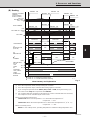
1. Specifications
1
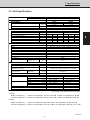
1-1 Unit Specifications
MODEL No. Indoor Unit SPW-X253GH56
Outdoor Unit SPW-C253GH5
POWER SOURCE 220 - 230 - 240 V / 1 Phase / 50 Hz
PERFORMANCE Cooling Heating
Capacity kW 7.3 8
BTU / h 25,000 27,000
Air circulation (Hi/Me/Lo) m3 / h 1,140/1,020/840
Moisture removal(High) Liters/ h 3.6 -
ELECTRICAL RATINGS
Voltage rating V 220 230 240 220 230 240
Available voltage range V 198 - 264 198 - 264
Running amperes* A 14.9 15.1 15.2 14.8 14.9 15.1
Max. running amperes** A 17 17 17 16.1 16 15.9
Power input kW 3.15 3.2 3.25 3.12 3.17 3.22
Power factor % 96.1 92.1 89.1 95.8 92.5 88.9
C.O.P W / W 2.32 2.28 2.25 2.56 2.52 2.48
Max. starting amperes A 69 72 75 68 71 74
FEATURES
Controls / Thermostat control Microprocessor / I.C. thermostat
Timer ON / OFF 72-hours / ON/OFF 24-hours & Program
Fan speeds Indoor/Outdoor 3 and Automatic control/ 2 (Auto)
Airflow direction (Indoor) Automatic (Remote control)
Air filter Washable, easy access
Remote controller (Option) Wired : RCS-SH80TG / Wireless : RCS-SH80TGWL
Refrigerant control Electronic Refrigerant Control Valve
Drain pump (drain connection) Max. head 25cm above drain connection (25A,OD32mm)
Compressor Rotary
Operation sound Indoor - Hi/Me/Lo dB - A 37 / 35 / 31
Outdoor - Hi dB - A 52
REFRIGERANT TUBING
Limit of tubing length m (ft.) 50 (164)
Limit of tubing length at shipment m (ft.) 30 (98)
Limit of elevation difference m (ft.) Outdoor unit is higher than indoor unit: 50 (164)
between the two units Outdoor unit is lower than indoor unit: 30 (98)
Refrigerant tube Narrow tube mm (in) 6.35 (1 / 4)
outer diameter
Wide tube mm (in) 15.88 (5 / 8)
Refrigerant amount at shipment kg R22 - 3.0
DIMENSIONS & WEIGHT Indoor unit (include panel) Outdoor unit
Unit dimensions Height mm (in) 328 (12-29/32) 735 (28-30/32)
Width mm (in) 860 (33-27/32) 940 (37)
Depth mm (in) 860 (33-27/32) 340 (13-12/32)
Package dimensions Height mm (in) 410 (16-5/32) 826 (32-17/32)
Width mm (in) 988 (38-29/32) 1,016 (40)
Depth mm (in) 988 (38-29/32) 416 (16-12/32)
Net weight kg (lb) 30 (66) 71 (157)
Shipping weight kg (lb) 47 (104) 77 (170)
Shipping volume m
3
(Cu. ft.) 0.4 (14.1) 0.349 (12.3)
DATA SUBJECT TO CHANGE WITHOUT NOTICE
Cooling :
Rating conditions(*) : Indoor air temperature 27
°
C DB / 19
°
C WB, Outdoor air temperature 35
°
C DB
Full load conditions(**) :Indoor air temperature 35
°
C DB / 25
°
C WB, Outdoor air temperature 45
°
C DB
Heating :
Rating conditions(*) : Indoor air temperature 20
°
C DB, Outdoor air temperature 7
°
C DB / 6
°
C DB
Full load conditions(**) :Indoor air temperature 24
°
C DB, Outdoor air temperature 24
°
C DB / 15.5
°
C WB

– 9 –
SM830033
1
1. Specifications
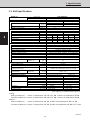
1-1 Unit Specifications
MODEL No. Indoor Unit SPW-X253GH56
Outdoor Unit SPW-C253GH8
POWER SOURCE 380 - 400 - 415 V / 3N / 50 Hz
PERFORMANCE Cooling Heating
Capacity kW 7.3 8
BTU / h 25,000 27,000
Air circulation (Hi/Me/Lo) m3 / h 1,140/1,020/840
Moisture removal(High) Liters/ h 3.6 -
ELECTRICAL RATINGS
Voltage rating V 380 400 415 380 400 415
Available voltage range V 342 - 456 342 - 456
Running amperes* A 4.9 4.7 4.5 5 4.8 4.7
Max. running amperes** A 5.4 5.2 5 5.7 5.5 5.3
Power input kW 2.76 2.79 2.82 2.82 2.83 2.87
Power factor % 85.6 85.7 87.2 85.7 85.1 85
C.O.P W / W 2.64 2.62 2.59 2.84 2.83 2.79
Max. starting amperes A 27 29 30 26 28 29
FEATURES
Controls / Thermostat control Microprocessor / I.C. thermostat
Timer ON / OFF 72-hours / ON/OFF 24-hours & Program
Fan speeds Indoor/Outdoor 3 and Automatic control/ 2 (Auto)
Airflow direction (Indoor) Automatic (Remote control)
Air filter Washable, easy access
Remote controller (Option) Wired : RCS-SH80TG / Wireless : RCS-SH80TGWL
Refrigerant control Electronic Refrigerant Control Valve
Drain pump (drain connection) Max. head 25cm above drain connection (25A,OD32mm)
Compressor Rotary
Operation sound Indoor - Hi/Me/Lo dB - A 37 / 35 / 31
Outdoor - Hi dB - A 52
REFRIGERANT TUBING
Limit of tubing length m (ft.) 50 (164)
Limit of tubing length at shipment m (ft.) 30 (98)
Limit of elevation difference m (ft.) Outdoor unit is higher than indoor unit: 50 (164)
between the two units Outdoor unit is lower than indoor unit: 30 (98)
Refrigerant tube Narrow tube mm (in) 6.35 (1 / 4)
outer diameter
Wide tube mm (in) 15.88 (5 / 8)
Refrigerant amount at shipment kg R22 - 3.0
DIMENSIONS & WEIGHT Indoor unit (include panel) Outdoor unit
Unit dimensions Height mm (in) 328 (12-29/32) 735 (28-30/32)
Width mm (in) 860 (33-27/32) 940 (37)
Depth mm (in) 860 (33-27/32) 340 (13-12/32)
Package dimensions Height mm (in) 410 (16-5/32) 826 (32-17/32)
Width mm (in) 988 (38-29/32) 1,016 (40)
Depth mm (in) 988 (38-29/32) 416 (16-12/32)
Net weight kg (lb) 30 (66) 71 (157)
Shipping weight kg (lb) 47 (104) 77 (170)
Shipping volume m
3
(Cu. ft.) 0.4 (14.1) 0.349 (12.3)
DATA SUBJECT TO CHANGE WITHOUT NOTICE
Cooling :
Rating conditions(*) : Indoor air temperature 27
°
C DB / 19
°
C WB, Outdoor air temperature 35
°
C DB
Full load conditions(**) :Indoor air temperature 35
°
C DB / 25
°
C WB, Outdoor air temperature 45
°
C DB
Heating :
Rating conditions(*) : Indoor air temperature 20
°
C DB, Outdoor air temperature 7
°
C DB / 6
°
C DB
Full load conditions(**) :Indoor air temperature 24
°
C DB, Outdoor air temperature 24
°
C DB / 15.5
°
C WB

– 10 –
SM830033
1. Specifications
1
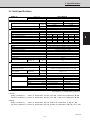
1-1 Unit Specifications
MODEL No. Indoor Unit SPW-X363GH56
Outdoor Unit SPW-C363GH8
POWER SOURCE 380 - 400 - 415 V / 3N / 50 Hz
PERFORMANCE Cooling Heating
Capacity kW 10.6 11.4
BTU / h 36,000 39,000
Air circulation (Hi/Me/Lo) m3 / h 1,920/1,680/1,320
Moisture removal(High) Liters/ h 4.7 -
ELECTRICAL RATINGS
Voltage rating V 380 400 415 380 400 415
Available voltage range V 342 - 456 342 - 456
Running amperes* A 5.3 5.1 5 5.3 5.1 5.1
Max. running amperes** A 6.3 6.1 6 6 6 5.9
Power input kW 3.08 3.1 3.12 3.12 3.15 3.16
Power factor % 88.3 87.7 86.8 89.4 89.2 86.2
C.O.P W / W 3.44 3.42 3.4 3.65 3.62 3.61
Max. starting amperes A 31 33 34 31 33 34
FEATURES
Controls / Thermostat control Microprocessor / I.C. thermostat
Timer ON / OFF 72-hours / ON/OFF 24-hours & Program
Fan speeds Indoor/Outdoor 3 and Automatic control/ 2 (Auto)
Airflow direction (Indoor) Automatic (Remote control)
Air filter Washable, easy access
Remote controller (Option) Wired : RCS-SH80TG / Wireless : RCS-SH80TGWL
Refrigerant control Electronic Refrigerant Control Valve
Drain pump (drain connection) Max. head 25cm above drain connection (25A,OD32mm)
Compressor Rotary
Operation sound Indoor - Hi/Me/Lo dB - A 43 / 40 / 36
Outdoor - Hi dB - A 53
REFRIGERANT TUBING
Limit of tubing length m (ft.) 50 (164)
Limit of tubing length at shipment m (ft.) 30 (98)
Limit of elevation difference m (ft.) Outdoor unit is higher than indoor unit: 50 (164)
between the two units Outdoor unit is lower than indoor unit: 30 (98)
Refrigerant tube Narrow tube mm (in) 9.52 ( 3 / 8 )
outer diameter
Wide tube mm (in) 19.05 ( 3 / 4 )
Refrigerant amount at shipment kg R22 - 3.5
DIMENSIONS & WEIGHT Indoor unit (include panel) Outdoor unit
Unit dimensions Height mm (in) 358 (14-3/32) 1,235 (48-20/32)
Width mm (in) 1,150 (45-9/32) 940 (37)
Depth mm (in) 860 (33-27/32) 340 (13-12/32)
Package dimensions Height mm (in) 440 (17-10/32) 1,326 (52-7/32)
Width mm (in) 1,278 (50-10/32) 1,016 (40)
Depth mm (in) 988 (38-29/32) 416 (16-12/32)
Net weight kg (lb) 38 (84) 94 (207)
Shipping weight kg (lb) 62 (137) 101 (223)
Shipping volume m
3
(Cu. ft.) 0.556 (19.6) 0.56 (19.8)
DATA SUBJECT TO CHANGE WITHOUT NOTICE
Cooling :
Rating conditions(*) : Indoor air temperature 27
°
C DB / 19
°
C WB, Outdoor air temperature 35
°
C DB
Full load conditions(**) :Indoor air temperature 35
°
C DB / 25
°
C WB, Outdoor air temperature 45
°
C DB
Heating :
Rating conditions(*) : Indoor air temperature 20
°
C DB, Outdoor air temperature 7
°
C DB / 6
°
C DB
Full load conditions(**) :Indoor air temperature 24
°
C DB, Outdoor air temperature 24
°
C DB / 15.5
°
C WB

– 11 –
SM830033
1
1. Specifications
1-1 Unit Specifications
MODEL No. Indoor Unit SPW-X483GH56
Outdoor Unit SPW-C483GH8
POWER SOURCE 380 - 400 - 415 V / 3N / 50 Hz
PERFORMANCE Cooling Heating
Capacity kW 14 16
BTU / h 47,800 54,600
Air circulation (Hi/Me/Lo) m3 / h 1,920/1,680/1,320
Moisture removal(High) Liters/ h 7.4 -
ELECTRICAL RATINGS
Voltage rating V 380 400 415 380 400 415
Available voltage range V 342 - 456 342 - 456
Running amperes* A 8.5 8.6 8.8 8.9 9 9.2
Max. running amperes** A 9.1 9.2 9.3 9.7 9.4 9.1
Power input kW 4.84 5.04 5.13 5.14 5.29 5.37
Power factor % 86.5 84.6 81.1 87.7 84.8 81.2
C.O.P W / W 2.89 2.78 2.73 3.11 3.02 2.98
Max. starting amperes A 71 73 75 71 73 75
FEATURES
Controls / Thermostat control Microprocessor / I.C. thermostat
Timer ON / OFF 72-hours / ON/OFF 24-hours & Program
Fan speeds Indoor/Outdoor 3 and Automatic control/ 2 (Auto)
Airflow direction (Indoor) Automatic (Remote control)
Air filter Washable, easy access
Remote controller (Option) Wired : RCS-SH80TG / Wireless : RCS-SH80TGWL
Refrigerant control Electronic Refrigerant Control Valve
Drain pump (drain connection) Max. head 25cm above drain connection (25A,OD32mm)
Compressor Scroll
Operation sound Indoor - Hi/Me/Lo dB - A 43 / 40 / 36
Outdoor - Hi dB - A 55
REFRIGERANT TUBING
Limit of tubing length m (ft.) 50 (164)
Limit of tubing length at shipment m (ft.) 30 (98)
Limit of elevation difference m (ft.) Outdoor unit is higher than indoor unit: 50 (164)
between the two units Outdoor unit is lower than indoor unit: 30 (98)
Refrigerant tube Narrow tube mm (in) 9.52 ( 3 / 8 )
outer diameter
Wide tube mm (in) 19.05 ( 3 / 4 )
Refrigerant amount at shipment kg R22 - 4.5
DIMENSIONS & WEIGHT Indoor unit (include panel) Outdoor unit
Unit dimensions Height mm (in) 358 (14-3/32) 1,235 (48-20/32)
Width mm (in) 1,150 (45-9/32) 940 (37)
Depth mm (in) 860 (33-27/32) 340 (13-12/32)
Package dimensions Height mm (in) 440 (17-10/32) 1,326 (52-7/32)
Width mm (in) 1,278 (50-10/32) 1,016 (40)
Depth mm (in) 988 (38-29/32) 416 (16-12/32)
Net weight kg (lb) 38 (84) 108 (238)
Shipping weight kg (lb) 62 (137) 115 (254)
Shipping volume m
3
(Cu. ft.) 0.556 (19.6) 0.56 (19.8)
DATA SUBJECT TO CHANGE WITHOUT NOTICE
Cooling :
Rating conditions(*) : Indoor air temperature 27
°
C DB / 19
°
C WB, Outdoor air temperature 35
°
C DB
Full load conditions(**) :Indoor air temperature 35
°
C DB / 25
°
C WB, Outdoor air temperature 45
°
C DB
Heating :
Rating conditions(*) : Indoor air temperature 20
°
C DB, Outdoor air temperature 7
°
C DB / 6
°
C DB
Full load conditions(**) :Indoor air temperature 24
°
C DB, Outdoor air temperature 24
°
C DB / 15.5
°
C WB

– 12 –
SM830033
1. Specifications
1
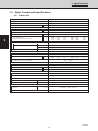
1-2 Major Component Specifications
(A) Indoor Unit
MODEL No. SPW-X253GH56
Source 220 - 230 - 240 V / 1 phase / 50 Hz
Controller P.C.B. Ass’y CR - X253GH (Microprocessor)
Fan (Number…diameter) mm Turbo (1...ø490)
Fan Motor
Model…Nominal output W SFG6X - 41A5P...40 W
Source 220 - 230 - 240 V / 1 phase / 50 Hz
No. of pole…rpm(230 V, High) rpm. 6...470
Coil resistance Ω BRN – WHT : 114.0 , ORG – YEL : 66.4
(Ambient temperature 20°C) WHT – VLT : 23.9 , WHT – PNK : 77.4
VLT – ORG : 12.4 , YEL – BLK : 82.1
Safety device
Operating temperature Open °C 130 ± 8 °C
Close °C 79 ± 15 °C
Run capacitor VAC, µF 440 V, 4µF
Electronic Refrigerant Control Valve
Solenoid control model DKV - MOZS582E0
Coil resistance (at 20°C) Ω ORG – GRY : 46 , YEL – GRY : 46
RED – GRY : 46 , BLK – GRY : 46
Solenoid control valve model IKV - 24D12
Heat exchanger
Coil Aluminum plate fin / Copper tube
Rows…fin pitch mm 2…1.7
Face area m
2
0.295
Panel
Model No. PNR - X253GHA
Dew proof heater 240 V, 26 W
Auto louver motor M2LB24ZA12
Auto louver motor...Rated V, W, rpm. AC 240 V, 3W, 2.5 rpm
Coil resistance (at 25 °C) Ω 15,620 Ω ± 15%
Drain Pump WP20SL - 21
Rated V, W AC 230 V, 50 Hz, 14.7 W
Total head & capacity 400 mm, 600 cc/min

– 13 –
SM830033
1
1. Specifications
MODEL No. SPW-X363GH56 SPW-X483GH56
Source 220 - 230 - 240 V / 1 phase / 50 Hz
Controller P.C.B. Ass’y CR - X253GH (Microprocessor)
Fan (Number…diameter) mm Turbo (1...ø490)
Fan Motor
Model…Nominal output W SFG6X - 61A3P...60 W
Source 220 - 230 - 240 V / 1 phase / 50 Hz
No. of pole…rpm(230 V, High) rpm. 6...530
Coil resistance Ω BRN – WHT : 71.1 , ORG – YEL : 22.7
(Ambient temperature 20 °C) WHT – VLT : 8.7 , VLT – PNK : 43.2
VLT – ORG : 13.3 , YEL – BLK : 126.7
Safety device
Operating temperature Open °C 130 ± 8 °C
Close °C 79 ± 15 °C
Run capacitor VAC, µF 440 V, 6µF
Electronic Refrigerant Control Valve
Solenoid control model EKV - MOZS584E0
Coil resistance (at 20 °C) Ω ORG – GRY : 46 , YEL – GRY : 46
RED – GRY : 46 , BLK – GRY : 46
Solenoid control valve model HKV - 30D16
Heat exchanger
Coil Aluminum plate fin / Copper tube
Rows…fin pitch mm 2…1.7
Face area m
2
0.479
Panel
Model No. PNR - X483GHA
Dew proof heater 240 V, 31 W
Auto louver motor M2LB24ZA12
Auto louver motor...Rated V, W, rpm. AC 240 V, 3W, 2.5 rpm
Coil resistance (at 25 °C) Ω 15,620 Ω ± 15%
Drain Pump WP20SL - 21
Rated V, W AC 230 V, 50 Hz, 14.7 W
Total head & capacity 400 mm, 600 cc/min
1-2 Major Component Specifications
(A) Indoor Unit

– 14 –
SM830033
1. Specifications
1
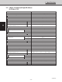
1-2 Major Component Specifications
(B) Outdoor Unit
Unit Model No. SPW-C253GH5
Source 220 - 230 - 240 V / 1 phase / 50 Hz
Controller P.C.B. Ass'y CR - C253GH5 (Microprocessor)
Control circuit fuse 250 V, 3.15 A
Compressor Rotary (Hermetic)
Model ..... number C - R221H5W
Source 220 - 240 V / 1 phase / 50 Hz
Nominal output W 2200
Compressor oil cc 1500
Coil resistance Ω C – R : 0.76 , R – S : 3.52
(Ambient temperature 25 °C) C – S : 2.76
Safety devices
Overload relay models Internal type
Operating temperature Open °C160± 5
Close °C87± 11
Crank case heater 240V, 25 W
Refrigerant amount at shipment kg R22 - 3.0
High pressure switch ACB
-
1TB07
Set pressure OFF kg/cm
2
30
ON kg/cm
2
24 ± 2.0
Fan Propeller
Number...diameter mm 1 ..... ø460
Fan speeds 2 (AUTO)
Fan motor
Model KFC6T - 91C5P
Source 220 - 230 - 240 V / 1 phase / 50 Hz
No. of pole ..... rpm (230V, High / Med.) 6...772 / 376
Nominal output W 70
Coil resistance Ω WHT – BRN : 127.3 , VLT – YEL : 15.0
(Ambient temperature 20°C) WHT – VLT : 56.7 , YEL – PNK : 7.2
Safety device Internal type
Operating temperature Open °C130± 8
Close °C79± 15
Run capacitor VAC, µF 440 V, 6 µF
Heat exchange
Coil Aluminium plate fin / Copper tube
Rows ..... fin pitch mm 2 ..... 2.0
Face area m
2
0.616
+ 2.0
+ 0.5

– 15 –
SM830033
1
1. Specifications
Unit Model No. SPW-C253GH8
Source 380 - 400 - 415 V / 3 phase / 50 Hz
Controller P.C.B. Ass'y CR - C253GH (Microprocessor)
Control circuit fuse 250 V, 3.15 A
Compressor Rotary (Hermetic)
Model ..... number C - R224H8U
Source 380 - 400 - 415 V / 3 phase / 50 Hz
Nominal output W 2400
Compressor oil cc 1350
Coil resistance Ω T – R : 5.54 , R – S : 5.54
(Ambient temperature 25 °C) S – T : 5.54
Safety devices
Overload relay models Internal type
Operating temperature Open °C120± 5
Close °C98± 11
Crank case heater 240V, 25 W
Refrigerant amount at shipment kg R22 - 3.0
High pressure switch ACB
-
1TB07
Set pressure OFF kg/cm
2
30
ON kg/cm
2
24 ± 2.0
Fan Propeller
Number...diameter mm 1 ..... ø460
Fan speeds 2 (AUTO)
Fan motor
Model KFC6T - 91C5P
Source 220 - 230 - 240 V / 1 phase / 50 Hz
No. of pole ..... rpm (230 V, High / Med.) 6...772 / 376
Nominal output W 70
Coil resistance Ω WHT – BRN : 127.3 , VLT – YEL : 15.0
(Ambient temperature 20°C) WHT – VLT : 56.7 , YEL – PNK : 7.2
Safety device Internal type
Operating temperature Open °C130± 8
Close °C79± 15
Run capacitor VAC, µF 440 V, 6 µF
Heat exchange
Coil Aluminium plate fin / Copper tube
Rows ..... fin pitch mm 2 ..... 2.0
Face area m
2
0.616
1-2 Major Component Specifications
(B) Outdoor Unit
+ 2.0
+ 0.5

– 16 –
SM830033
1. Specifications
1
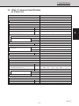
1-2 Major Component Specifications
(B) Outdoor Unit
Unit Model No. SPW-C363GH8 SPW-C483GH8
Source 380 - 400 - 415 V / 3 phase / 50 Hz
Controller P.C.B. Ass'y CR - C253GH (Microprocessor)
Control circuit fuse 250 V, 3.15 A
Compressor Rotary (Hermetic) Scroll (Hermetic)
Model ..... number C - R243H8V ZR61KC - TFD-522
Source 380 - 400 - 415 V / 3 phase / 50 Hz
Nominal output W 2,400 3,700
Compressor oil cc 1,350 2,130
Coil resistance Ω T – R : 5.54 , R – S : 5.54 T 1 – T2: 2.72 , T2 – T3 : 2.72
(Ambient temperature 25 °C) S – T : 5.54 T 3 – T1: 2.72
Crank case heater 240 V, 25 W 240 V, 36 W
Safety devices
Overload relay models Internal type
Operating temperature Open °C120± 5130
Close °C98± 11 61
Refrigerant amount at shipment kg R22 - 3.5 R22 - 4.5
High pressure switch ACB
-
1TB07
Set pressure OFF kg/cm
2
30
ON kg/cm
2
24 ± 2.0
Fan Propeller
Number...diameter mm 2 ..... ø460
Fan speeds 2 (AUTO)
Fan motor
Model KFC6T - 91C5P × 2
Source 220 - 230 - 240 V / 1 phase / 50 Hz
No. of pole ..... rpm (230V, High / Med.) 6...772 / 376
Nominal output W 70 W × 2
Coil resistance Ω BRN – WHT : 127.3 , VLT – YEL : 15.0
(Ambient temperature 20°C) WHT – VLT : 56.7 , YEL – PNK : 7.2
Safety device Internal type
Operating temperature Open °C130± 8
Close °C79± 15
Run capacitor VAC, µF 440 V, 6 µF × 2
Heat exchange
Coil Aluminium plate fin / Copper tube
Rows ..... fin pitch mm 2 ..... 2.0
Face area m
2
1.08
+ 2.0
+ 0.5

– 17 –
SM830033
1
1. Specifications
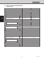
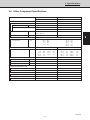
1-3 Other Component Specifications
Unit model No. Indoor Unit Outdoor Unit
SPW-X253GH56 SPW-C253GH5, SPW-C253GH8
Power Transformer ATR - II215TA ATR - I65B
Rated
Primary V. Hz AC 230 V, 50 Hz AC 230, 50 Hz
Secondary 10.2V , 1.4 A 14 V , 0.4 A
14 V , 0.5 A —
Coil resistance Ω WHT – WHT : 84 , BRN – BRN : 0.7 WHT – WHT : 300 , BRN – BRN : 2.2
RED – RED : 2.7
Thermal cut off temperature °C 145 145
Thermistor (Coil sensor) PBC - 41E - S25, PBC - 41E - S26, PBC - 41E-S4, PBC - 41E - S14
Coil resistance kΩ –10 °C : 23.7 , 10 °C : 9.7
– 5 °C : 18.8 , 20 °C : 6.5
0 °C : 15.0 , 30 °C : 4.4
5 °C : 12.1 , 40 °C : 3.1
45 °C : 2.6
Thermistor (Room or coil sensor) KTEC - 35 - S6 PTC - 51H - S1
Coil resistance kΩ 0 °C : 16.5 , 40 °C : 2.7 60 °C : 13.8 , 90 °C : 5.1
5 °C : 12.8 , 45 °C : 2.2 70 °C : 9.7 , 100 °C : 3.8
10 °C : 10.0 , 50 °C : 1.8 75 °C : 8.2 , 110 °C : 2.8
20 °C : 6.3 , 55 °C : 1.5 80 °C : 7.0 , 120 °C : 2.2
30 °C : 4.0 , 85 °C : 5.9 , 130 °C : 1.7
Relay — FMCA - 1SZ607
Coil rated V — AC 220 - 240 V
Contact rating V.A — AC 440 V, 13 A
Coil resistance (at 25 °C) Ω — —
Solenoid control valve or coil
Solenoid control valve IKV - 24D12 CHV - 0201
Solenoid coil DKV - MOZS582E0 CHV - 01AJ504D1
Drain pump WP20SL - 21 —
Rated AC 230 V, 14.7 W —
Float switch FS - 3502 - 204 —
Rated (Contact rated) AC 230 V, 50 W —

– 18 –
SM830033
1. Specifications
1
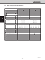
Unit model No. Indoor Unit Outdoor Unit
SPW-X363GH56 SPW-X483GH56 SPW-C363GH8 SPW-C483GH8
Power Transformer ATR - II215TA ATR - I65B
Rated
Primary V. Hz AC 230 V, 50 Hz AC 230, 50 Hz
Secondary 10.2V , 1.4 A 14 V , 0.4 A
14 V , 0.5 A —
Coil resistance Ω WHT – WHT : 84 , BRN – BRN : 0.7 WHT – WHT : 300 , BRN – BRN : 2.2
RED – RED : 2.7
Thermal cut off temperature °C 145 145
Thermistor (Coil sensor) PBC - 41E - S25, PBC - 41E - S36, PBC - 41E - S4, PB3M - 41E - S4
Coil resistance kΩ –10 °C : 23.7 , 10 °C : 9.7
–5 °C : 18.8 , 20 °C : 6.5
0 °C : 15.0 , 30 °C : 4.4
5 °C : 12.1 , 40 °C : 3.1
45 °C : 2.6
Thermistor (Room or coil sensor) KTEC - 35 - S6 PTC - 51H - S1
Coil resistance kΩ 0 °C: 16.5 , 40 °C: 2.7 60 °C: 13.8 , 90 °C: 5.1
5 °C: 12.8 , 45 °C: 2.2 70 °C: 9.7 , 100 °C: 3.8
10 °C: 10.0 , 50 °C: 1.8 75 °C: 8.2 , 110 °C: 2.8
20 °C: 6.3 , 55 °C: 1.5 80 °C: 7.0 , 120 °C: 2.2
30 °C: 4.0 85 °C: 5.9 , 130 °C: 1.7
Relay — FMCA - 1SZ607
Coil rated V — AC 220 - 240 V
Contact rating V.A — AC 440 V, 13 A
Coil resistance (at 25 °C) Ω — —
Solenoid control valve or coil
Solenoid control valve HKV - 30D16 CHV - 0301 CHV - 0401
Solenoid coil EKV - MOZS584E0 CHV - 01AJ504D1
Drain pump WP20SL - 21 —
Rated AC 230 V, 14.7 W —
Float switch FS - 3502 - 204 —
Rated (Contact rated) AC 230 V, 50 W —
1-3 Other Component Specifications

– 19 –
SM830033
1
1. Specifications
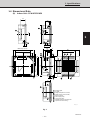
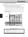
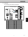
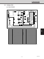
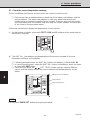
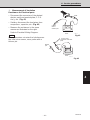
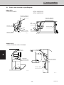
Fig. 1
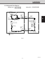
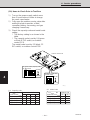
1-4 Dimensional Data
(A) Indoor Unit : SPW-X253GH56
860
100
760
500
500
298 30
205
125
12
12
48
860
820 (Ceiling opening)
820 (Ceiling opening)
61
730 (Suspention bolt pitch)
Panel center
590 (Suspention bolt pitch)
345 35
Air intake grille
Air outlet
Refrigerant liquid line (ø 6.35)
Refrigerant gas line (ø 15.88)
Drain connection
Power supply entry
For discharge duct
Humidifier (option) mounting hole
Suspention bolt mounting
342 15
X-view
0410_X_S
207
100
205
61
760
50 150
255
207
9
9

– 20 –
SM830033
1. Specifications
1
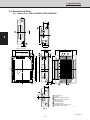
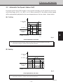
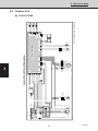
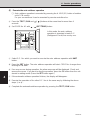
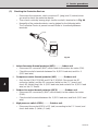
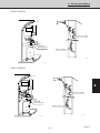
Fig. 2
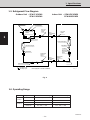
1-4 Dimensional Data
(A) Indoor Unit : SPW-X363GH56,SPW-X483GH56
1150
1050
790
500
328
30
218
125
860
1110 (Ceiling opening)
820 (Ceiling opening)
61
1020 (Suspention bolt pitch)
Panel center
590 (Suspention bolt pitch)
490 40
Air intake grille
Air outlet
Refrigerant liquid line (ø9.52)
Refrigerant gas line (ø19.05)
Drain connection
Power supply entry
For discharge duct
Humidifier (option) mounting hole
Suspention bolt mounting
X-view
0183_X_I
218
14535
210
60
760
70 165
285
210
100 100
9
9
342 15
12
48
12

– 21 –
SM830033
1
1. Specifications
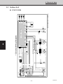
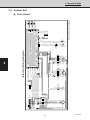
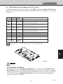
400
380
20
340
20
110660170
735
280
307
940
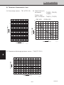
Dimension : mm
Hole for anchor bolt (4-ø13)
Refrigerant tube joint (narrow tube)
Flare connection 1/4 in (6.35 mm)
Refrigerant tube joint (wide tube)
Flare connection 5/8 in (15.88 mm)
Refrigerant tubing inlet
Power supply inlet
0411_C_S
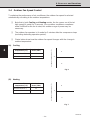
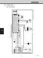
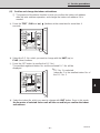
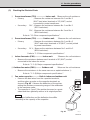
1-4 Dimensional Data
(B) Outdoor Unit : SPW-C253GH5, SPW-C253GH8
Fig. 3
Page is loading ...
Page is loading ...
Page is loading ...
Page is loading ...
Page is loading ...
Page is loading ...
Page is loading ...
Page is loading ...
Page is loading ...
Page is loading ...
Page is loading ...
Page is loading ...
Page is loading ...
Page is loading ...
Page is loading ...
Page is loading ...
Page is loading ...
Page is loading ...
Page is loading ...
Page is loading ...
Page is loading ...
Page is loading ...
Page is loading ...
Page is loading ...
Page is loading ...
Page is loading ...
Page is loading ...
Page is loading ...
Page is loading ...
Page is loading ...
Page is loading ...
Page is loading ...
Page is loading ...
Page is loading ...
Page is loading ...
Page is loading ...
Page is loading ...
Page is loading ...
Page is loading ...
Page is loading ...
Page is loading ...
Page is loading ...
Page is loading ...
Page is loading ...
Page is loading ...
Page is loading ...
Page is loading ...
Page is loading ...
Page is loading ...
Page is loading ...
Page is loading ...
Page is loading ...
Page is loading ...
Page is loading ...
Page is loading ...
Page is loading ...
Page is loading ...
Page is loading ...
Page is loading ...
Page is loading ...
Page is loading ...
Page is loading ...
Page is loading ...
Page is loading ...
Page is loading ...
Page is loading ...
Page is loading ...
Page is loading ...
Page is loading ...
Page is loading ...
Page is loading ...
Page is loading ...
Page is loading ...
Page is loading ...
Page is loading ...
Page is loading ...
Page is loading ...
Page is loading ...
Page is loading ...
Page is loading ...
Page is loading ...
Page is loading ...
Page is loading ...
Page is loading ...
Page is loading ...
-
 1
1
-
 2
2
-
 3
3
-
 4
4
-
 5
5
-
 6
6
-
 7
7
-
 8
8
-
 9
9
-
 10
10
-
 11
11
-
 12
12
-
 13
13
-
 14
14
-
 15
15
-
 16
16
-
 17
17
-
 18
18
-
 19
19
-
 20
20
-
 21
21
-
 22
22
-
 23
23
-
 24
24
-
 25
25
-
 26
26
-
 27
27
-
 28
28
-
 29
29
-
 30
30
-
 31
31
-
 32
32
-
 33
33
-
 34
34
-
 35
35
-
 36
36
-
 37
37
-
 38
38
-
 39
39
-
 40
40
-
 41
41
-
 42
42
-
 43
43
-
 44
44
-
 45
45
-
 46
46
-
 47
47
-
 48
48
-
 49
49
-
 50
50
-
 51
51
-
 52
52
-
 53
53
-
 54
54
-
 55
55
-
 56
56
-
 57
57
-
 58
58
-
 59
59
-
 60
60
-
 61
61
-
 62
62
-
 63
63
-
 64
64
-
 65
65
-
 66
66
-
 67
67
-
 68
68
-
 69
69
-
 70
70
-
 71
71
-
 72
72
-
 73
73
-
 74
74
-
 75
75
-
 76
76
-
 77
77
-
 78
78
-
 79
79
-
 80
80
-
 81
81
-
 82
82
-
 83
83
-
 84
84
-
 85
85
-
 86
86
-
 87
87
-
 88
88
-
 89
89
-
 90
90
-
 91
91
-
 92
92
-
 93
93
-
 94
94
-
 95
95
-
 96
96
-
 97
97
-
 98
98
-
 99
99
-
 100
100
-
 101
101
-
 102
102
-
 103
103
-
 104
104
-
 105
105


Ask a question and I''ll find the answer in the document
Finding information in a document is now easier with AI
Related papers
-
Sanyo SPW-C253GH5 User manual
-
-
-
-
-
-
-
-
-
Other documents
-
Electrolux RH30WC60GS Product information
-
-
 Argo Clima AS52AL Datasheet
-
Fujitsu UTY-RNNUM Installation guide
-
Panasonic CZ-RWSC1U User manual
-
Electrolux EE66WP35PS Product information
-
Manitowoc Ice i0500 Traditional Remote 1ph Product information
-
Premier AA-2118 User manual
-
Amana PALW540RMW1 Datasheet
-
