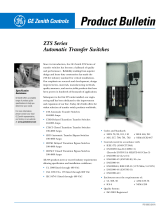
Emerson Separately Mounted User manual
- Category
- Fire protection
- Type
- User manual
Emerson Separately Mounted Power Transfer Switches are designed for use when pump room size constraints do not allow an integral controller/transfer switch configuration. They are built in two configurations for use when the alternate (emergency) source is a generator set, and come with a variety of standard features, including emergency power source disconnect switch, normal source isolating switch and circuit breaker, 3-pole transfer switch mechanism, control module, pilot lights, audible alarms, and output contacts.
Emerson Separately Mounted Power Transfer Switches are designed for use when pump room size constraints do not allow an integral controller/transfer switch configuration. They are built in two configurations for use when the alternate (emergency) source is a generator set, and come with a variety of standard features, including emergency power source disconnect switch, normal source isolating switch and circuit breaker, 3-pole transfer switch mechanism, control module, pilot lights, audible alarms, and output contacts.


-
 1
1
-
 2
2
Emerson Separately Mounted User manual
- Category
- Fire protection
- Type
- User manual
Emerson Separately Mounted Power Transfer Switches are designed for use when pump room size constraints do not allow an integral controller/transfer switch configuration. They are built in two configurations for use when the alternate (emergency) source is a generator set, and come with a variety of standard features, including emergency power source disconnect switch, normal source isolating switch and circuit breaker, 3-pole transfer switch mechanism, control module, pilot lights, audible alarms, and output contacts.
Ask a question and I''ll find the answer in the document
Finding information in a document is now easier with AI
Related papers
Other documents
-
Eaton LMR PLUS User manual
-
Hubbell Switch LX-440 User manual
-
 3G Green Green Globe ZTSCT100 User manual
-
CAT LEHE4651-04 User manual
-
Eaton Magnum Transfer Switch User manual
-
Simplicity 071098 User manual
-
Eaton Cutler-Hammer SPB Instructions Manual
-
Simplicity 071098 User manual
-
Simplicity 071112 User manual
-
MGE UPS Systems STS 600A User manual


