Page is loading ...

308–341
Rev. G
Supersedes F
First
choice when
quality counts.
02748
INSTRUCTIONS-PARTS
LIST
INSTRUCTIONS
This
manual contains important
warnings and information.
READ AND KEEP FOR REFERENCE.
Optimiser
2K
HVLP T
wo Component
Adhesive Spray Gun
100 psi (7 bar) Maximum Working Fluid and Air Pressure
This gun is for use with water-based contact adhesives only
Part
No. 949–239, Series C
U.S.
Patent Pending
GRACO INC. P.O. BOX 1441
MINNEAPOLIS, MN
55440–1441
COPYRIGHT
1993, GRACO INC.
Graco
Inc. is registered to I.S. EN ISO 9001

Table
of Contents
Warnings
2
.
. . . . . . . . . . . . . . . . . . . . . . . . . . . . . . . . . . . . .
Selection
Chart
4.
. . . . . . . . . . . . . . . . . . . . . . . . . . . . . . .
Air
Flow and Atomizing Pressure
5.
. . . . . . . . . . . . . . . .
Installation 6
. . . . . . . . . . . . . . . . . . . . . . . . . . . . . . . . . . . .
Setup
and Shutdown
7.
. . . . . . . . . . . . . . . . . . . . . . . . . .
Ratio
Check
13.
. . . . . . . . . . . . . . . . . . . . . . . . . . . . . . . . .
Daily
Gun Care, Flushing, and Cleaning
14.
. . . . . . . . .
Troubleshooting 17
. . . . . . . . . . . . . . . . . . . . . . . . . . . . . . .
Service 18
. . . . . . . . . . . . . . . . . . . . . . . . . . . . . . . . . . . . . .
Parts 24
. . . . . . . . . . . . . . . . . . . . . . . . . . . . . . . . . . . . . . . .
Technical
Data
26.
. . . . . . . . . . . . . . . . . . . . . . . . . . . . . . .
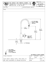
Dimensions 26
. . . . . . . . . . . . . . . . . . . . . . . . . . . . . . . . . . .
Graco
Phone Number
Back Cover
.
. . . . . . . . . . . . . . . . .
Warranty Back
Cover
.
. . . . . . . . . . . . . . . . . . . . . . . . . . . .
Symbols
Warning Symbol
WARNING
This
symbol alerts you to the possibility of serious
injury or death if you do not follow the instructions.
Caution Symbol
CAUTION
This
symbol alerts you to the possibility of damage to
or destruction of equipment if you do not follow the
instructions.
WARNING
INSTRUCTIONS
EQUIPMENT MISUSE HAZARD
Equipment
misuse can cause the equipment to rupture, malfunction or start unexpectedly and result in
serious injury
.
This equipment is for professional use only
.
Read all instruction manuals, tags, and labels before operating the equipment.
Use the equipment only for its intended purpose. If you are uncertain about usage, call your Graco
distributor.
Do not alter or modify this equipment. Use only genuine Graco parts and accessories.
Check equipment daily
. Repair or replace worn or damaged parts immediately
.
Use this equipment only in low pressure, air spray systems.
Do not exceed the maximum working pressure of the lowest rated system component. This equip
-
ment has a
100 psi (7 bar) maximum working fluid and air pressure
.
Do not lift pressurized equipment.
Use fluids or solvents that are compatible with equipment wetted parts. See the
T
echnical Data
section of all equipment manuals. Read the fluid and solvent manufacturer
’
s warnings.
Comply with all applicable local, state and national fire, electrical and other safety regulations.

WARNING
PRESSURIZED EQUIPMENT HAZARD
Spray
from the gun, hose leaks or ruptured components can splash fluid in the eyes or on the skin and
cause serious injury
.
Do not stop or deflect fluid leaks with your hand, body
, glove or rag.
Follow the
Pressure Relief Procedure
on page 7 when: you are instructed to relieve pressure;
stop spraying; clean, check or servicing the equipment; and install or clean fluid nozzles.
Never point the spray gun at anyone or at any part of the body
.
Never put hand or fingers over the spray nozzle.
T
ighten all fluid connections before operating the equipment.
Check the hoses, tubes and couplings daily
. Replace worn, damaged or loose parts immediately
.
Permanently coupled hoses cannot be repaired; replace the entire hose.
Route hoses away from traf
fic areas, sharp edges, moving parts and hot surfaces.
Do not use the hoses to pull equipment.
FIRE AND EXPLOSION HAZARD
Poor
air ventilation, open flames or sparks can cause a hazardous condition and result in fire or explo
-
sion and serious injury
.
Provide fresh air ventilation to avoid the buildup of flammable fumes from solvent or the fluid being
sprayed.
Extinguish all open flames or pilot lights in the spray area.
Electrically disconnect all equipment in the spray area.
Keep the spray area free of debris, including solvent, rags and gasoline.
Do not turn on or of
f any light switch in the spray area while operating or if fumes are present.
Do not smoke in the spray area.
Do not operate a gasoline engine in the spray area.
TOXIC FLUID HAZARD
Hazardous
fluids or toxic fumes can cause serious injury or death if splashed in the eyes or on the
skin, inhaled, or swallowed.
Know the specific hazards of the fluid you are using. Read the fluid manufacturer
’
s warnings.
Store hazardous fluid in an approved container
. Dispose of hazardous fluid according to all local,
state and national guidelines.
Dress appropriately for your application. W
ear protective eyewear
, noise protection for the ears, a
personal respirator
, gloves and clothing.

Selection
Chart
Includes:
Needle/
Nozzle/Air
Cap
Kit
P/N
Needle
Assembly
P/N
Air Cap
P/N
Nozzle
P/N
Replacement
Needle T
ip
P/N
Orifice Size
949–276
238–703 185–794 185–756 191–564 0.020” (0.508 mm)
949–277
238–703 185–794 185–757 191–564 0.026” (0.660 mm)
949–278
238–703 185–794 185–700 191–564 0.030” (0.762 mm)
949–279
238–217 185–794 185–701 191–016 0.042” (1.067 mm)
949–280
238–218 185–794 185–702 191–017 0.055” (1.397 mm)
949–281
238–219 185–795 185–703 191–018 0.070” (1.778 mm)
949–282
238–220 185–796 185–704 191–019 0.086” (2.184 mm)
Selecting a Needle/Nozzle/Air Cap Kit
The
kits range in size to provide different fluid flow
rates.
Use the fluid nozzle that will give the required flow
with the fluid adjustment knob opened four full turns
counterclockwise and an adhesive pressure of
approximately 5 to 20 psi (0.35 to 1.4 bar).
For low flow rates or light viscosity fluid, select the
smaller nozzle sizes.
For high flow rates or high viscosity fluid, select the
larger nozzle sizes.
Using an air cap size that is smaller than the
nozzle/needle size
is not recommended.
T
o help select the proper needle/nozzle size, a fluid
pressure gauge may be connected temporarily to
the gun fluid inlet to determine the fluid pressure.
See
Service
to install the parts.
Selection Problems and Solutions
PROBLEM POSSIBLE
CAUSE
SOLUTION
Fluid pressure
required to achieve
flow rate is too high
Using set with
too small of an
orifice
Use needle/
nozzle/air cap
set with larger
orifice
Using a low pres
-
sure setting, the
fluid flow
is too high,
making it necessary
to restrict needle
travel to reduce fluid
flow
Using set with
too large of an
orifice
Use needle/
nozzle/air cap
set with small
-
er orifice
Fluid system will not
operate at low
enough fluid pres
-
sure
Fluid regulator is
not installed or
air regulator is
not sensitive
enough
Add low pres
-
sure fluid regu
-
lator or add
more sensitive
air regulator on
pressure pot

308-3415
Air
Flow and Atomizing Pressure
NOTE:
All tests completed with the fan air fully open.
Air Flow
0
2
4
6
8
10
12
14
16
18
20
22
24
26
28
30
15 25 35 45 55 65 75 85 95
AIR FLOW (scfm)
GUN
AIR INLET PRESSURE (psi)
Atomizing Pressure Versus
Activator Inlet Pressure
Air
flowing through the gun creates back pressure,
which the activator must overcome before beginning to
flow
. The chart below shows the minimum activator
pressure required to overcome the atomizing air
pressure. Higher pressures may be necessary to
maintain the mix ratio.
GUN
AIR INLET PRESSURE (psi)
0
2
4
6
8
10
12
14
16
18
20
22
24
26
28
30
15 25 35 45 55 65 75 85 95
MINIMUM
ACTIVAT
OR INLET PRESSURE (psi)
Atomizing Air Pressure
(inlet pressure vs. atomizing pressure)
GUN
AIR INLET PRESSURE (psi)
0
2
4
6
8
10
12
14
16
18
20
15 25 35 45 55 65 75 85 95
NOMINAL
AT
OMIZING PRESSURE (psi)
Gun
Inlet Pressure
Nominal Atomizing Pressure
15 psi (1.05 bar)
1.5 psi (0.1
1 bar)
25 psi (1.75 bar)
3.0 psi (0.22 bar)
35 psi (2.45 bar)
4.5 psi (0.33 bar)
45 psi (3.15 bar)
6.0 psi (0.42 bar)
55 psi (3.85 bar)
8.5 psi (0.62 bar)
65 psi (4.55 bar)*
10.0 psi (0.70 bar)
75 psi (5.25 bar)
13.0 psi (0.95 bar)
85 psi (5.95 bar)
15.5 psi (1.14 bar)
95 psi (6.97 bar)
18.0 psi (1.32 bar)
*
For compliant operation, operate at 65 psi (4.55 bar) or less

6308-341
Installation
KEY
A Optimiser
2K Spray Gun
B
Air Inlet; 1/4 npsm
C
Air Hose
Recommend
5/16” (7.9 mm) ID hose;
Optional
3/8” (9.5 mm) ID hose
D
Gun Air Shut-of
f V
alve
E
Gun Air Regulator
F
Air Filter
G
Air Supply Line
H
Pressure Pot Air Shut-of
f V
alve
J
Pressure Pot Air Regulator
K
Activator Pressure Pot
L
Activator Fluid Shut-of
f V
alve
M
Activator Fluid Hose
N
Activator Inlet 1/8–27 npt(f)
P
Adhesive Pressure Pot
Q
Adhesive Fluid Shut-of
f V
alve
R
Adhesive Fluid Hose
S
Adhesive Inlet; 3/8 npsm (R3/8–19)
A
S
B
N
D
EF
02750
G
C
HJ
HJKL
PQ
M
R
Fig.
1
Fluid Compatibility of Accessories
When
selecting system components to supply the
adhesive and activator
, consider the following:
Adhesives and activators are water-based and
corrosive. A
void carbon steel, unplated brass,
copper
, and aluminum. Stainless steel, nickel-
plated brass and most plastics are usually accept
-
able.
Piston pumps are not recommended for use with
adhesives as they are often shear sensitive and will
coagulate in your equipment. Stainless steel
pressure pots function well in place of a pump and
fluid pressure regulator. On drum or tote tank
supplied systems, plastic diaphragm pumps are
often used.
Some adhesives will coagulate in fluid pressure
regulators due to shear
. Consult with the fluid
supplier for regulator recommendations.
Refer to Fig. 1 and see Form No. 305–591 for the
accessories recommended to install the system.
Consult with the fluid supplier or Graco for specific
recommendations.
Ventilate the Spray Booth
WARNING
FLAMMABLE/TOXIC
FLUID HAZARD
T
o avoid hazardous concentrations of
flammable or toxic fumes, spray only in
a properly ventilated spray booth.
Comply with all applicable local, state
and national fire and safety regulations.

308-3417
Installation
Air Line Accessories
The
gun air line must have an air regulator (E) to
control air pressure to the gun. See Fig. 1.
If the gun air source does not have a filter
,
install a
filter (F) on the gun air line to ensure a dry
, clean
air supply
.
T
o eliminate the need to shut of
f the air pressure at
the air supply
, install a quick-disconnect at the gun
air inlet fitting.
Fluid Line Accessories
If
you are using diaphragm pumps to supply adhe
-
sive or activator to the gun(s), install a fluid regula
-
tor (T) on each gun fluid supply line to control fluid
pressure to the gun(s). See Fig. 9, page 9.
Install a fluid filter in the gun fluid supply lines to
avoid clogging the fluid nozzle. A 100 mesh filter is
recommended for the activator supply line to avoid
clogging the activator needle and orifice.
Use 5/32 or 1/4 inch I.D. tubing for the activator
supply line.
Setup
and Shutdown
Pressure Relief Procedure
WARNING
PRESSURIZED
EQUIPMENT HAZARD
The equipment stays pressurized until pressure is
manually relieved. To reduce the risk of serious
injury from pressurized fluid, accidental spray from
the gun or splashing fluid, follow this procedure
whenever you:
Are instructed to relieve pressure
Stop spraying
Check, clean or service any system equipment
Install or clean fluid nozzles
1.
Close the adhesive and activator shut-of
f valves
(Q and L). See Fig. 2.
2. T
rigger the gun into the spray booth* to relieve the
fluid pressures and clear excess activator from the
gun. See Fig. 3.
*If
the gun has been flushed with solvent, be sure to spray
the solvent into a grounded metal waste container
.
3. Close
the atomizing air shut-of
f valve (D). See
Fig. 4.
Fig. 2
L
02059
Q
Fig. 3
02753
Fig. 4
D
02780

Setup
and Shutdown
Removing and Installing the Fluid Nozzle
Follow
this procedure whenever you remove and install
a fluid nozzle. See page 4 to select a nozzle or
needle/nozzle/air cap kit.
1.
Follow the
Pressure Relief Procedure
on
page 7.
2.
Remove the air cap ring (12), air cap (19), and air
cap seal (47). See Fig. 5.
3. T
rigger the gun while you remove the fluid nozzle
(20) with the gun wrench (35).
Fig. 5
02757A
35
20
12, 19
47
17
Lightly
lubricate baf
fle o-ring (17)
Apply
PTFE
adhesive to nozzle (20) threads. T
rigger gun and
tighten
to 125–150 in-lbs (14–17 N
Sm)
2
1
1
2
CAUTION
Trigger
the gun whenever you tighten or remove the
fluid nozzle (20) to pull the needle away from the
nozzle seating surface and avoid scratching it.
4.
Apply PTFE
r
adhesive to the threads of the fluid
nozzle (20) you are installing.
5.
Lubricate the baf
fle o-ring (17).
CAUTION
Lubricate the baf
fle o-ring (17) before installing the
fluid nozzle (20). A dry o-ring will prevent the nozzle
from tightening properly and adhesive may leak
inside the gun.
6. T
rigger the gun while you install the fluid nozzle
(20) with the gun wrench (35). T
ighten it to 125 to
150 in-lbs (14 to 17 N
Sm).
CAUTION
When tightening the fluid nozzle (20), do not
exceed
150 in-lbs (17 N
S
m) torque. Over-tightening can
damage the nozzle, af
fect the spray pattern, and is
unnecessary to guarantee a seal.
7.
Install the air cap seal (47), air cap ring (12), and
air cap (19).

308-3419
Setup
and Shutdown
WARNING
EQUIPMENT
MISUSE HAZARD
This gun is for use with water-based contact adhe-
sives only. Any other use of the gun could cause
unsafe
operating conditions or damage to the gun.
1. Connect the air line.
A. Connect
the air hose (C) to the gun air inlet
(B). See Fig. 6.
C
B
02751
Fig. 6
1
1
1/4
npsm
B. Connect
the other end of the air hose (C) to a
regulated air supply line (G).
See Fig. 7.
NOTE:
Fig. 7 shows the air supply line filter (F), air
regulator (E), and air shut-of
f valve (D).
01990
C
EF
Fig. 7
G
D
2. Flush the adhesive and activator fluid
lines with water and blow them out
with air before connecting them to the
gun.
3. Connect the adhesive fluid hose.
A. Connect
the fluid hose (R) to the gun adhesive
inlet (S). See Fig. 8.
S
02752
Fig. 8
R
1
1
3/8–18
npsm [R 3/8–19]
compound thread
B. Connect
the other end of the fluid hose (R) to
a regulated fluid supply line (U–see Fig. 9) or a
pressure tank (P–see Fig. 1, page 6).
NOTE:
Fig. 9 shows the fluid supply line regulator
(T) and fluid shut-of
f valves (Q).
R
T
02777
Fig. 9
U
Q

Setup
and Shutdown
4. Connect the activator tube.
A. Connect
the fitting (V) and tube (M) to the gun
activator inlet. See Fig. 10.
B.
Connect the other end of the fluid tube (M) to a
regulated fluid supply line or a pressure tank.
Fig. 10
02784
V
M
5. Position the Air Cap for a vertical or
horizontal spray pattern. See Fig. 11.
Vertical Pattern
Horizontal Pattern
Fig.
1
1
02020
6. Adjust the spray pattern.
WARNING
COMPONENT
RUPTURE HAZARD
Do not exceed the
100 psi (7 bar)
maximum fluid and air pressure
of this gun.
Higher pressures can cause parts to rupture and
result in serious injury
.
NOTE:
Refer to the
Atomizing Pressure V
ersus
Activator Inlet Pressure
chart on page 5 to help set
air and activator pressures.
A.
Close the fluid adjustment valve by turning the
knob (8) fully clockwise. Then turn the knob
counterclockwise four full turns to open it. See
Fig. 12.
02784
Fig. 12
8
Open
B.
Open the adhesive fluid shut-of
f valve (Q). Ad
-
just the fluid flow with the fluid regulator (T)
installed in the gun fluid line (see Fig. 13) or
the air regulator on the adhesive tank (see Fig.
1). T
ypical industrial flow rates will vary with
regulator pressures from 5 to 20 psi (0.35 to
1.4 bar).
Fig. 13
T
02778
Q

Setup
and Shutdown
6. Adjust the spray pattern. (continued)
C. Hold
the gun parallel to the floor and adjust the
adhesive fluid pressure until you have a 1 to 6
inch (25.4 to 152.4 mm) straight fluid stream
before the stream falls of
f. See Fig. 14.
02754
1–6
in.
(25.4–152.4 mm)
straight fluid stream
Fig.
14
NOTE:
A larger fluid nozzle at a reduced adhesive
pressure will maintain the same flow rate, but slow
down the fluid stream. See Fig. 15. This allows the
atomizing air to act on the fluid longer and improve
the atomization.
Fluid Stream of Fluid Nozzles
at the Same Flow Rate
Fig. 15
02755
0.042
(1.067)
0.055
(1.397)
0.070
(1.778)
0.086
(2.184)
0.110
(2.794)
Nozzle
Orifice Size in inches (mm)
D. To
further reduce the volume of adhesive out
-
put at the gun, turn the fluid adjustment knob
(8) clockwise as needed. See Fig. 16. How
-
ever
, for the best results, adjust the adhesive
pressure or use a dif
ferent size needle/nozzle/
air cap combination to change the fluid flow
.
Refer to page 4.
CAUTION
Continuously spraying with the fluid adjustment knob
closed
,
will cause accelerated wear on the fluid
needle and trigger/air valve shaft interface.
If the fluid adjustment knob is fully closed, the gun
will emit only air and activator
.
Fig. 16
8
Close
02784
E.
Open the pattern adjusting valve by turning the
knob (13a) fully counterclockwise. See Fig. 17.
02784
Fig. 17
13a
Open
(wider
pattern)
Close
(narrower
pattern)

Setup
and Shutdown
6. Adjust the spray pattern. (continued)
F. Set
the gun air supply pressure at 40 psi
(2.8 bar), using the gun atomizing air regulator
(E). See Fig. 18.
NOTE:
Use the fluid manufacturer recommendations if
available and refer to the
Atomizing Pressure
V
ersus Activator Inlet Pressure
chart on
page 5 when adjusting the gun.
Local laws may limit the maximum pressure to
10 psi (0.7 bar) at the air cap for HVLP com
-
pliance.
Fig. 18
E
01997
G.
Hold the gun about 6 to 8 inches (150 to
200 mm) from the test piece and test the spray
pattern and atomization.
H.
The spray pattern may be too wide with the
pattern adjustment knob (13a) fully open. T
urn
the pattern adjustment knob clockwise until
you have the desired pattern size. See Fig. 17,
page 1
1.
NOTE:
Some
pattern air is required to supply the
activator; do not close the pattern adjustment knob
completely.
I.
Check the atomization quality again. If neces
-
sary
, increase the gun air supply pressure with
the air regulator (E) in 5 psi (0.35 bar) incre
-
ments until you have the desired atomization.
J.
If the atomization is still unacceptable, install a
larger fluid nozzle size to reduce the fluid
stream. Refer to Fig. 15. See page 8 to
remove and install a fluid nozzle.
K.
Repeat steps 6.E to 6.J until you have the
desired spray pattern and atomization.
NOTE:
T
o eliminate a fan pattern at low atomizing
pressures, it may help to remove the activator air
restrictor (55). See Fig. 34, page 19.
7. Adjust the activator fluid flow.
CAUTION
When
the activator is being supplied to the gun, the
atomizing air must be on before triggering the gun to
avoid contaminating the atomizing air with activator
.
Open the activator supply valve (L) and increase
the fluid pressure until the desired amount of acti
-
vator is sprayed with the adhesive. The typical fluid
pressure range is 8 to 20 psi (0.56 to 1.40 bar).
See
Ratio Check
, page 13.
Fig. 19
L
02776
8. Shut down the system at
the end of the
work-shift and before checking, adjusting, cleaning
or repairing the system. Follow the
Pressure Re
-
lief Procedure
on page 7.
9. Place the gun nozzle in soapy water
over-night
to avoid having the tip clog with
hardened material. Do not immerse the entire gun.
Fig. 20
02785

Ratio
Check
NOTE:
Y
ou cannot sample the adhesive and activator
at the same time. The adhesive must be checked with
the atomizing air of
f, while the activator must be
checked with the atomizing air on.
1. Check the ratio of the adhesive.
A. Weigh
an empty beaker
.
B.
Close the atomizing air shut-of
f valve.
C.
Close the activator shut-of
f valve.
D. T
rigger the gun into the beaker for 15 seconds
to dispense the adhesive.
E.
Follow the
Pressure Relief Procedure
on
page 7.
F. W
eigh the adhesive, subtract the weight of the
beaker
, then multiply the figure by 4 to obtain
the weight per minute of the adhesive.
2. Check the ratio of the activator.
A. Weigh
an empty beaker
.
B.
Cover the beaker with a loose cover to deflect
any over-spray
. See Fig. 21.
C.
Disconnect the red tube from the activator
valve.
D.
Connect the ratio check tube (54) (supplied
with the gun) to the activator valve outlet fitting
(52
1
) as shown in Fig. 21. T
urn the front fitting
(52
2)
toward
the front of the gun.
E.
Close the adhesive shut-of
f valve.
F.
Open the atomizing air shut-of
f valve.
G.
Open the activator shut-of
f valve.
Fig. 21
02786A
54
52
2
52
1
H.
Place the ratio check tube (54) into the beaker
as shown in Fig. 21.
I.
Direct the spray gun into the booth. T
rigger the
gun for 1 minute to dispense the activator
through the tube and into the beaker
.
J.
Follow the
Pressure Relief Procedure
on
page 7.
K.
Remove the beaker cover
. W
eigh the activator
and subtract the weight of the beaker to obtain
the weight per minute of the activator
.
3. Adjust the ratio as needed.
Adjust
the activator
supply pressure to change the
ratio of adhesive to activator, then check the ratio
again.
Once the ratio is set, do not change the adhesive
or activator supply pressure settings or turn the
gun fluid adjustment knob. Any change to the flow
of either fluid will change the mix ratio.

Daily
Gun Care, Flushing, and Cleaning
CAUTION
Do
not point the gun up while cleaning it as this
may allow fluid to enter the gun air passages.
Do not use metal tools to clean the air cap holes
as this may scratch them and distort the spray
pattern.
Do not immerse the gun.
Squeeze the excess fluid out of the cleaning cloth
before wiping the gun.
Typically
the gun should be flushed or cleaned with
soap and water. If solvent is used, do not use me-
thylene chloride with formic or propionic acid as it
will
damage nylon components.
1. General system maintenance.
A. Clean
the fluid and air line filters daily
.
B.
Check for fluid leakage from the gun and the
fluid hoses. Tighten fittings or replace equip
-
ment as needed.
C.
Flush the gun with water if it will not be used in
the next three days. Follow the flushing proce
-
dure below
.
2. Flush the gun.
A. Follow
the
Pressure Relief Procedure
on
page 7.
B.
Disconnect the adhesive and activator sup
-
plies and connect the supply lines to a water
supply.
C.
Point the gun down into the spray booth* and
spray until the water sprays clear
. See Fig. 22.
*If
the gun is flushed with solvent, be sure to spray the
solvent into a grounded metal waste container
.
2753
Fig.
22
D. T
urn of
f the fluid supplies.
E.
Follow the
Pressure Relief Procedure
on
page 7.
3. Clean the gun.
A. After
relieving pressure, disconnect the activa
-
tor and adhesive supply lines (M and R) from
the gun. See Fig. 23.
02799
R
Fig. 23
M

308-34115
Daily
Gun Care, Flushing, and Cleaning
3. Clean the gun. (continued)
B. Disconnect
the air supply line (C). See Fig. 24.
02800
C
Fig. 24
C.
Remove the air cap ring (12), air cap (19), air
cap seal (47), and fluid nozzle (20) as
instructed on page 8.
02757A
35
20
12, 19
47
Fig. 25
D.
Soak the air cap ring (12), air cap (19), and
fluid nozzle (20) in soapy water
.
E.
Dip a soft-bristle brush into soapy water
, point
the gun down, and clean the front of the gun.
Do not use a wire brush. See Fig. 26.
Fig. 26
02775A
F.
Clean the air cap ring, air cap, and fluid nozzle
daily
, minimum, using a soft-bristle brush. See
Fig. 27. Clean out air cap holes with a soft im
-
plement, such as a toothpick, to avoid damag
-
ing surfaces.
Fig. 27
02011

16308-341
Daily
Gun Care, Flushing, and Cleaning
3. Clean the gun. (continued)
G. Install
the fluid nozzle (20) air cap seal (47), air
cap ring (12), and air cap (19) as instructed on
page 8.
H.
Dampen a soft cloth with soapy water;
squeeze out the excess water
. Point the gun
down and wipe of
f the outside of it.
Fig. 28
02782A
4. Lubricate the following gun parts daily,
using
Part No. 1
1
1–265 lubricant. See Fig. 29.
Pattern adjustment valve threads
Fluid adjustment knob threads
T
rigger pivot pin
Fluid needle shaft
Activator nuts, in the area where they contact
the trigger
Fig. 29
02756B
Lubricate
Lubricate
Lubricate

308-34117
Troubleshooting
PROBLEM CAUSE SOLUTION
Fluid
flow is fluttering while
spraying
1.
Fluid nozzle is not tight enough
2.
Fluid filter is clogged
3.
Fluid adjustment knob is not
properly set
4. Baffle (item 11) is installed wrong or
damaged
1. See page 8 to install the fluid nozzle
correctly
2. Check
the fluid filter
3. Adjust the fluid adjustment knob for
less feathering or use a larger size
nozzle
4. Check
if the baf
fle protrusion is proper
-
ly
inserted into the gun insert hole,
see
page 19; replace
the
baf
fle if damaged
Fluid
flow fades while spraying
high viscosity fluids
1. Air
hose size is too
restricted for higher
air flows
2.
Fluid pressure is too low
1. Use
larger 3/8 in. ID air hose; order part
no.
185–353
2. Raise
the fluid supply pressure or
use
a
smaller fluid nozzle
Pattern becomes of
f-set or heavy
on ends
1.
Fluid nozzle is too tight
2.
Air cap is too tight
3.
Air cap horn holes are plugged
1. See page 8 to install the fluid nozzle
correctly; replace the nozzle if
damaged
2. Loosen
the air cap retaining ring
3. Clean the air cap horn holes with a
non-metallic
item, such as a toothpick
Fluid
system will not operate at low
enough fluid pressure [below
10 psi (0.7 bar)]
There is no fluid regulator
, or the air regu
-
lator on the pressure pot is not sensitive
enough at low pressures
Add a low pressure fluid regulator on the
fluid line or add a more sensitive air regu
-
lator on the pressure pot.
Adhesive residue forms on spray
nozzle
1. Activator
is dispensing
in the atomizing
air
2. Activator
valve is leaking or not seating
properly
3. Baffle
(item 1
1)
is leaking at baf
fle pro
-
trusion
4. Baffle
is leaking at nozzle seal
5. Air cap taper is not sealing to nozzle
taper
1. Do
not trigger the gun with the activator
on
and atomizing air of
f
2. Clean
the needle,
seat, and packings;
lubricate
packings and re-assemble
3. Clean
and re-assemble
the baf
fle with
a
small amount of
PTFE
pipe sealant
on the baffle protrusion or replace
the
baffle.
Make sure that the baf
fle protru
-
sion is properly inserted into the gun
insert
hole, see page 19
4. Clean the baffle and replace the
nozzle
seal
5.
Clean and re-tighten the air cap
Adhesive collecting in air passages
The adhesive nozzle’
s internal seal is
leaking
Clean the nozzle and seat; see page 8
to install the fluid nozzle correctly
When the gun is triggered, the
adhesive dispenses before the ac
-
tivator or the activator dispenses
before the adhesive
Activator needle hex nuts are not tight Adjust the activator needle hex nuts until
the adhesive and activator needles open
together

Service
Items Needed for Service
Gun
W
rench – provided
Seal Installation T
ool – provided
Adjustable W
rench
Screw Driver
Part No. 1
1
1–265 Lubricant
Soap and water
NOTE:
Gun Repair Kit 949–285 is available; see page
25. The following procedure covers the replacement of
all the kit parts.
Disassemble
1.
Follow the
Pressure Relief Procedure
on
page 7.
2.
Remove the air cap ring (12), air cap (19), air cap
seal (47), and fluid nozzle (20) as instructed on
page 8.
02757A
35
20
12, 19
47
Fig. 30
3.
Remove the nozzle seal (17). See Fig. 34.
4.
Remove the fluid adjustment knob (8) and spring
(16).
5.
Pull the fluid needle (21) out the back of the gun.
6.
Remove the gun and activator triggers (3 and 48).
7.
Remove the fluid adjustment nut (6), spring (15),
and air valve (14).
8.
Insert a thin-blade screw driver (A) through the
back of the gun and into the packing adjustment
nut (31) and remove the screw
. See Fig. 31.
Fig. 31
02762
31
A
9.
Push the three piece packing assembly (39) out
the back of the gun with the threaded end of the
fluid needle (21). See Fig. 32.
CAUTION
Do not use excessive force to push out the packing
assembly (39) or the u-cup seal (33) as this may
bend the fluid needle (21). Refer to Fig. 32 and 33. If
packings are difficult to remove, use a 3/16 in. plastic
rod to push them out.
Fig. 32
21
02759

308-34119
Service
10. Use
the threaded end of the fluid needle (21) to
push out the u-cup seal (33). See Fig. 33.
Fig. 33
21
02760
11.
Remove and disassemble the activator valve (49).
See Fig. 34. Use the threaded end of the activator
needle (49d) to push out the needle packings (49g
and 49r). Do not bend the end of the needle.
12.
Clean the parts. Check the fluid needles (21 and
49d) for damage or excessive wear
. Replace if
necessary.
13.
Check the baf
fle (1
1) for damage. If it is damaged,
carefully pry it off with a screwdriver and replace it.
Apply part no. 514–767 Form-A-Gasket Sealant to
the front area of the gun where the baf
fle sits and
to the baf
fle protrusion. Insert the baf
fle protrusion
into the gun insert hole.
14.
Lightly lubricate the parts indicated in Fig. 34 with
Part No. 1
1
1–265 lubricant.
Fig. 34
12
11
15
16
8
33
14
3
4
32
19
20
49e
39
31
6
22
21
1
4
1
1
1
2
48
52
51
49e
49
53
49a
49c
49b
49e
49f
49h
49d
49m
1
1
47
17
1
Lightly
lubricate
Lightly lubricate threads
Lightly lubricate contact area on trigger face
Apply
part no. 514–767 Form-A-Gasket Sealant to the front area
of
the gun where the baf
fle
sits and to the baf
fle protrusion. Insert
the
baf
fle protrusion into the gun insert hole.
2
3
52
1
1
2
49p
49j
49q
49r
49g
1
3
4
1
05885
49k
55
5
1
1

Service
Assemble
NOTE:
See Fig. 34, page 19, for the parts that need to
be lubricated.
1.
Insert the fluid needle (21) through the front of the
gun as shown in Fig. 35. Install the new packing
assembly (39) by placing them on the end of the
needle tip. Orientate the packings as shown in Fig.
35.
02763
Fig. 35
21
39
1
Washer
U-cup;
lips face
down
Spreader
2
3
1
2
3
2. Place
the packing adjustment nut (31) over the
packing assembly and start the threads into the
gun, then remove the needle.
3.
Insert a thin-blade screw driver (A) through the
back of the gun and into the packing adjustment
nut (31). See Fig. 36. Do not nick or damage parts
with the tool. T
urn the screw with the screw driver
(about 3 turns); the packing will still be loose.
02762
31
A
Fig. 36
4.
Place the new u-cup seal (33) on the seal installa
-
tion tool (42) with the u-cup lips facing the tool.
See Fig. 37.
5.
Push the u-cup seal (33) into the gun until a defi
-
nite snap is felt.
CAUTION
Apply even pressure to the u-cup seal (33) when
installing it to avoid damaging the seal.
Fig. 37
33
02023
42
1
1
U-cup
lips face the tool
/