Yamaha TR-1 Gold Marine Autopilot Operating instructions

Type
Operating instructions

This manual is also suitable for

Page 1
PN 906-1040-00
TR-1 Gold
Cylinder and Bracket
Mounting Instructions
Yamaha 6 HP: 2001 and Newer
Yamaha T8 HP: 2001 and Newer
Page 2
ITEM PART NUMBER QTY. NAME
1 330-1041-00 1 Nut, Standoff
2 130-1042-00 1 Bracket, Rod Eye Mounting
3 330-1013-00 1 Pin, Stern Pivot
4 380-1044-00 1 Channel, Cylinder MTG.
5 380-1046-00 1 Plate, Standoff Nut
6 310-0206-12 3 Hex Cap M6 X 12 MM
7 130-0084-02 1 “U” Bolt 1 3/4” ID 1/4-20
8 310-0067-01 1 Hair Pin Cotter LG.
9 310-0067-02 2 Hair Pin Cotter Med.
10 310-2501-25 1 Clevis Pin 1/4 D. X 1.25
11 310-0076-25 5 LW Split 1/4
Cylinder Kit Part Number 120-1040-00
Page 3
I. Installing the Cylinder & Mounting Bracket
Tools Required:
One; #1 (small) Phillips Screw Driver
One; Wrench ½ In.
One; Wrench 7/16 In.
One; Wrench 10 MM
One; 10 MM Socket Wrench
Thread lock (Loctite or similar (not shown)
Figure 2
Page 4
Step One:
Turn the steering friction lock on
the motor (just above the clamps
and below the front grip) all the
way to the left. (Full free steering
rotation. See motor manual if
necessary.) The motor must steer
very freely for the autopilot to
work. If there is still any drag in
the steering loosen the nut that
is controlled by the friction lever
to eliminate it. Tip the motor to
the up latched position. (Or full
up with the power tilt.) Remove
the upper front bolt and nut from
the top front of the lower motor
vibration isolation mounting
shroud. Be advised, we have seen
the bolts enter from different sides
on different motors.
Page 4
Figure 5
ITEM PART NO. QTY NAME
31 330-1002-00 1 Rod Eye, 5/16-24
33 310-0042-09 1 Hex Jam Nut 5/16-24
34 340-0900-00 1 Cylinder
35 321-0001-00 2 Fitting, Straight 1/8 NPT X 1/4
36 330-1101-00 1 Zinc Anode (Replaceable)
37 310-0040-26 1 Washer, Flat, Nylon 1/4 ID X .03
38 328-0901-00 2 Bushing 1/4 ID X 5/16 OD X 1/4”L
39 320-0001-03 2 Vinyl Cap 1/4”
40 328-0902-00 1 Cylinder Tail Bushing
38
35
39
40
34
Cylinder Kit PN 120-0900-00
Installation of cylinder and bracket kit
Install the bolt you just removed into the same hole
from the starboard side of the motor to the port side.
Put a little thread lock on the protruding end of the
bolt. Thread the bolt’s end in to the Standoff Nut
(item 1) as shown in gure 6 and tighten the it.
Remove the two rear bolts from the lower motor
vibration isolation mounting shroud, as shown in
gure 7.
Again, install the bolts you just removed into the
same holes from the starboard side of the motor to
the port side. Put a little thread lock on the protruding
ends of the bolts. Thread the bolts into non-at side
of the Standoff Nut Plate (item 5) as shown in gure
8 and tighten the them.
Page 5
Figure 6
Figure 7
Figure 8
Step Two:
Step Three:
Step Four:
Put a little thread lock on the ends of the three 6
MM Hex CAP Screws (item 6) and install them
through one Lock Washer each (item 11) and then
the Cylinder Mounting Channel (item 4) and into
the Standoff Nut and Plate (items 1 & 5) as shown
in gure 9. (Channel with the label facing you right
side up.) Keep the Channel perpendicular to the
motor down shaft and tighten the Screws.
Slide the small end of the Stern Pivot Pin (item 3)
through the holes at the rear of both anges. Secure
the Pivot Pin in place by inserting a Medium Hair
Pin Cotter (item 9) through the hole below the
bottom ange, as shown in gure 11.
Hold the Cylinder (item 34) with the Fittings (item
35) up (toward the top of the motor).
Line the hole in rear end cap of the Cylinder (item
34) with the hole in the top of the Stern Pivot Pin
(item 3). Slide the Clevis Pin (item 10) through
one Flat Nylon 1/4 Dia. Washer (item 12) and
into the top hole of the Stern Pivot Pin. Line up
the cross holes and put the Large Hair Pin Cotter
(item 8) through the cross holes in both Pins, as
shown in gure 10.
NOTE: If for any reason you need to
disconnect the steering actuator, pulling the
large Hair Pin Cotter and Clevis Pin will
disconnect them quickly.
Page 6
Figure 9
Figure 10
Figure 11
Step Four:
Step Five:
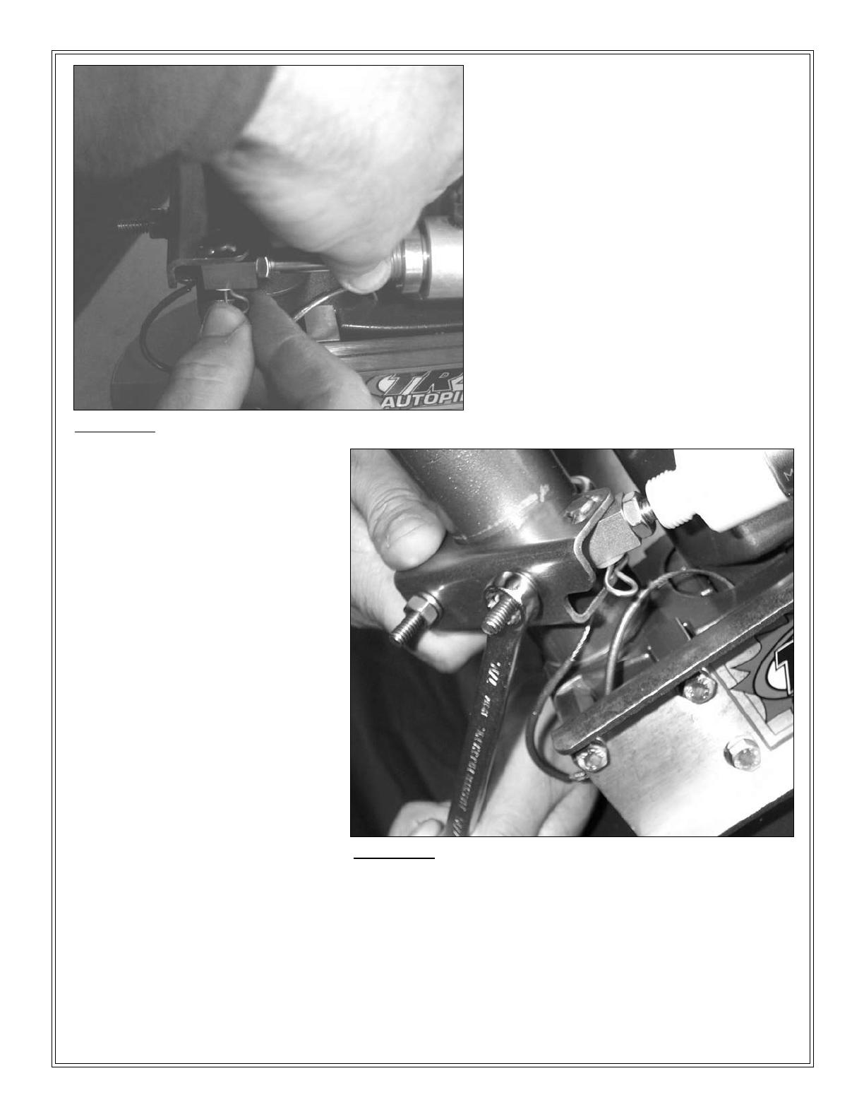
Place pin in the Rod Eye Mounting Bracket
(item 2) through the cylinder Rod Eye (item
31) as shown. (Leave the cylinder attached.)
Install the last Medium Hair Pin Cotter
(item 9) through the hole in the Bracket pin.
Turn the motor to the hard to port (prop
full to the left side of the boat) position.
This will push the cylinder rod fully
into the cylinder. Remove the nuts from
the “U” Bolt and install it around the
motor steering down tube above the
grease tting. Keeping the cylinder fully
retracted and the motor full to port, line
up the Rod Eye Mounting Bracket (item
2) against the motor steering down tube
with the “U” bolt through it. The several
models of motor have differences in
the location of the grease tting relative
to the shock mount (shaft length) This
causes the Rod Eye Mounting Bracket
to have to be mounted with the lower
ange notch around the grease tting on
some models and about a 1/4 inch below
it on others. Raise and lower the rod end of the cylinder against the pins holding it at the rear to rind
the center of its free travel. That will indicate where to locate the Rod Eye Mounting Bracket along
steering down tube. The Rod Eye Bracket should, also, always end up with the channel parallel to the
transom of the boat. Put a little thread lock on the protruding screw ends of the “U” Bolt. Mount and
tighten the last two Lock Washers (item 11) and the “U” Bolt Nuts, as shown in gure 13. Note: The
grounding wire around the grease tting may need to be rotated out of the way. In the future if you
wish to remove or install a cylinder. Just remove the Clevis Pin at the rear and slide the Rod Eye (item
31) off the Rod Eye Bracket pin after removing the cotters. This will leave the bracket in place.
Page 7
Figure 12
Figure 13
Step Six:
Step Seven:
Turn the motor hard over to port Figure 14. That will retract the Cylinder rod into the Cylinder. Check that the
Cylinder rod is still free to retract at least a little more. Next turn the motor hard over to starboard Figure 15.
That will extend the Cylinder rod out of the Cylinder. Check that the Cylinder rod is still free to extend at least
a little more. It should have additional travel in both directions. If it does not adjust the position of the Rod Eye
(item 31) on the Cylinder shaft. The Cylinder shaft should turn with your ngers if the Hex Jam Nut (item 33) is
loose. (If the shaft does not turn freely enough, use a thin 1/4 Inch open end wrench at the shaft’s wrench ats.)
Do not use any tool on the cylindrical part of the Cylinder shaft. If the shaft gets scratched, bent, or dinged the
seal will fail. With the cylinder properly adjusted, secure it by tightening the Hex Jam Nut against the Rod Eye
after putting a little thread lock between them. It is ready for plumbing. We suggest you put the original parts
in a container and, carefully store them. (You may eventually want to sell or trade in your motor, but we know
you will want to keep your TR-1 Autopilot.)
Page 8
Figure 14 Figure 15
Step Eight:
  • Page 1 1
  • Page 2 2
  • Page 3 3
  • Page 4 4
  • Page 5 5
  • Page 6 6
  • Page 7 7
  • Page 8 8

Yamaha TR-1 Gold Marine Autopilot Operating instructions

Type
Operating instructions
This manual is also suitable for

Ask a question and I''ll find the answer in the document

Finding information in a document is now easier with AI