Avalon Stoves Direct Vent Freestanding Stove User manual
- Category
- Cookers
- Type
- User manual
This manual is also suitable for

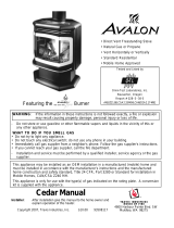
Featuring the
Burner
• Direct Vent Freestanding Stove
• Natural Gas or Propane
• Vent Horizontally or Vertically
• Standard Residential
• Mobile Home Approved
Tested and Listed by
Omni-Test Laboratories, Inc.
Beaverton, Oregon
Report # 028–S–28-5
ANSI Z21.88, CSA 2.33 M9 8, CAN/CGA 2.17-M91
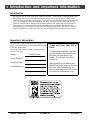
WARNING: If the information in these instructions is not followed exactly, a fire or explosion
may result causing property damage, personal injury or loss of life.
- Do not store or use gasoline or other flammable vapors and liquids in the vicinity of this or
any other appliance.
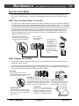
WHAT TO DO IF YOU SMELL GAS
• Do not try to light any appliance.
• Do not touch any electrical switch; do not use any phone in your building.
• Immediately call gas supplier from a neighbor's phone. Follow the gas supplier's instructions.
• If you cannot reach your gas supplier, call the fire department.
- Installation and service must be performed by a qualified installer, service agency or the gas
supplier.
This appliance may be installed as an OEM installation in a manufactured (mobile) home and
must be installed in accordance with the manufacturer’s instructions and the manufactured
home construction and safety standard, Title 24 CFR, Part 3280 or Standard for Installation in
Mobile Homes, CAN/CSA Z240 MH.
This appliance is only for use with the type(s) of gas indicated on the rating plate. A conversion
kit is supplied with the appliance.
Prairie Owner’s Manual
Installer: After installation give this manual to the home-owner
and explain operation of this heater.
Copyright 2007, T.I. $10.00 93508115 4050113
4800 Harbour Pointe Blvd. SW
Mukilteo, WA 98275

2 Introduction and Important Information
Travis Industries 93508115 4050113
Introduction
We welcome you as a new owner of an Avalon Prairie stove. In purchasing a Prairie you have joined
the growing ranks of concerned individuals whose selection of an energy system reflects both a
concern for the environment and aesthetics. The Prairie is one of the finest home heaters the world
over. This manual will explain the installation, operation, and maintenance of this stove. Please
familiarize yourself with the Owner's Manual before operating your heater and save the manual for
future reference. Included are helpful hints and suggestions that will make the operation and
maintenance of your new stove an easier and more enjoyable experience. We offer our continual
support and guidance to help you achieve the maximum benefit and enjoyment from your heater.
Important Information
No other Prairie Stove has the same serial number as
yours. The serial number is on the listing plate chained
to the gas control valve.
This serial number will be needed in case you require
service of any type.
Model: Avalon Prairie
Serial Number:
Purchase Date:
Purchased From:
Mail your Warranty Card
Today, and Save Your Bill of
Sale.
To receive full warranty coverage,
you will need to show evidence of
the date you purchased your
heater. Do not mail your Bill of
Sale to us.
We suggest that you attach your
Bill of Sale to this page so that you
will have all the information you
need in one place should the need
for service or information occur.

Table of Contents 3
Travis Industries 93508115 4050113
Introduction
Introduction & Important Information................2
Safety Precautions
Safety Precautions......................................4
Features & Specifications
Features ....................................................6
Installation Options......................................6
Heating Specifications..................................6
Dimensions.................................................6
Installation
Installation Warning......................................7
Packing List................................................7
Additional Items Required for Installation..........7
Installation Overview....................................7
Installation Hints..........................................8
Stove Clearances ........................................8
Mobile Home Requirements............................8
Heater Placement Requirements.....................9
Floor Protection Requirements........................9
Gas Line Installation.....................................10
Vent Requirements.......................................11
Approved Vent Configurations........................12
Restrictor Position...................................12
Measuring Vent Lengths...........................12
Vertical Term. with 0, 2, or 4 45° Elbows .......13
Hor. Term. with 1 90° Elbow........................14
Hor. Term. with 2 Elbows...........................15
Hor. Term. with 3 Elbows...........................16
Vertical Term. with 2 90° Elbows .................17
Vertical Term. with 3 Elbows......................18
Vent Termination Requirements ......................19
Finalizing the Installation
Leak Test...................................................20
Pilot Adjustment (if necessary).......................20
Air Shutter Adjustment (if necessary)...............21
Check Flame...............................................21
Glass Removal (& installation)........................22
Log Installation............................................24
Operation
Before You Begin.........................................25
Location of Controls .....................................25
Starting The Pilot .........................................26
Starting the Stove for the First Time.................27
Turning the Stove On and Off .........................27
Adjusting the Flame Height.............................27
Adjusting the Blower Speed (optional) ..............28
Normal Operating Sounds..............................28
Normal Operating Odors................................28
Maintenance
Maintaining Your Stove’s Appearance..............29
Yearly Service Procedure..............................29
Troubleshooting Table...................................30
How this Stove Works...................................31
What Turns the Main Burners On and Off......31
What Prevents Gas Buildup.......................31
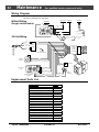
Wiring Diagram ............................................32
Replacement Parts List.................................32
Safety Label
Safety (Listing) Label....................................33
Warranty
Warranty....................................................34
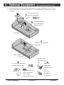
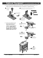
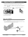
Optional Equipment
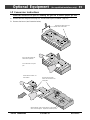
LP Conversion Kit ........................................35
Blower .......................................................38
Fireback.....................................................40
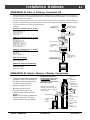
Installation Addenda
Class A Chimney Conversion..........................41
Interior Masonry Chimney Conversion..............41
Index
Index.........................................................42

4 Safety Precautions
Travis Industries 93508115 4050113
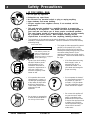
• IF YOU SMELL GAS:
* Do not light any appliance
* Extinguish any open flame
* Do not touch any electrical switch or plug or unplug anything
* Open windows and vacate building
* Call gas supplier from neighbor's house, if not reached, call fire
department
• This unit must be installed by a qualified installer to prevent the
possibility of an explosion. Your dealer will know the requirements in
your area and can inform you of those people considered qualified.
The room heater should be inspected before use and at least annually
by a qualified service person. More frequent cleaning may be
required due to excessive lint from carpeting, bedding material, etc.
• The instructions in this manual must be strictly adhered to. Do not use makeshift
methods or compromise in the installation. Improper installation will void the warranty
and safety listing.
For LPG only | Pout 11” W.C.
Look for this label:
If the label is present, the
heater is equipped for LP
(propane). If the label is
absent, the heater is equipped
for NG (natural gas).
• This heater is either approved for natural
gas (NG) or for propane (LP or LPG).
Burning the incorrect fuel will void the
warranty and safety listing and may cause
an extreme safety hazard. Direct
questions about the type of fuel used to
your dealer. Check for the label shown to
the right.
Ok
• Contact your local building
officials to obtain a permit
and information on any
installation restrictions or
inspection requirements in
your area. Notify your
insurance company of this
heater as well.
• If the flame becomes sooty,
dark orange in color, or
extremely tall, do not
operate the heater. Call
your dealer and arrange for
proper servicing.
• It is imperative that control
compartments, screens, or
circulating air passageways
of the heater be kept clean
and free of obstructions.
These areas provide the air
necessary for safe
operation.
?
• Do not operate the heater if
it is not operating properly in
any fashion or if you are
uncertain. Call your dealer
for a full explanation of your
heater and what to expect.
Gas
• Do not store or use gasoline
or other flammable liquids in
the vicinity of this heater.
• Do not use this appliance if
any part has been under
water. Immediately call a
qualified service technician
to inspect the appliance and
to replace any part of the
control system and any gas
control which has been
under water.

Safety Precautions 5
Travis Industries 93508115 4050113
• Do not place clothing or
other flammable items on or
near the heater. Because
this heater can be controlled
by a thermostat there is a
possibility of the heater
turning on and igniting any
items placed on or near it.
• Light the heater using the
built-in piezo igniter. Do not
use matches or any other
external device to light your
heater.
• Never remove, replace,
modify or substitute any part
of the heater unless
• The viewing glass should be
opened only for lighting the
pilot or conducting service.
• Any safety screen or guard
removed for servicing must
be replaced prior to
operating the heater.
• Do not operate with the
glass removed or damaged.
instructions are given in this
manual. All other work must
be done by a trained
technician. Don't modify or
replace orifices.
• Allow the heater to cool
before carrying out any
maintenance or cleaning.
• Operate the heater
according to the instructions
included in this manual.
• If the main burners do not
start correctly turn the gas
off at the gas control valve
and call your dealer for
service.
• The pilot flame must contact
the thermopile and
thermocouple (see the
illustration to the left). If it
does not, turn the gas
control valve to "OFF" and
call your dealer.
• This unit is not for use with
solid fuel
• Do not place anything inside
the firebox (except the
included fiber logs).
• If the fiber logs become
damaged, replace with
Travis Industries log set.
This
Manual
• Do not throw this manual
away. This manual has
important operating and
maintenance instructions
that you will need at a later
time. Always follow the
instructions in this manual.
• Do not touch the hot
surfaces of the heater.
Educate all children of the
danger of a high-
temperature heater. Young
children should be
supervised when they are in
the same room as the
heater.
• Plug the heater into a
120V grounded electrical
outlet. Do not remove the
grounding plug.
• Don’t route the electrical
cord in front of, over, or
under the heater
• Instruct everyone in the
house how to shut gas off to
the appliance and at the gas
main shutoff valve. The gas
main shutoff valve is usually
next to the gas meter or
propane tank and requires a
wrench to shut off.
• Travis Industries, Inc.
grants no warranty,
implied or stated, for
the installation or
maintenance of your
heater, and assumes
no responsibility of any
consequential
damage(s).

6 Features and Specifications
Travis Industries 93508115 4050113
Features:
- Works During Power Outages (millivolt system)
- High Efficiency
- Optional Thermostat or Remote Control
- Realistic "Wood Fire" Look
- Optional Blower for Quicker Heat Distribution
- Convenient Operating Controls
- Variable-Rate Heat Output
- Low Maintenance
Installation Options:
- Freestanding Stove
- Horizontal or Vertical Vent
- Residential or Mobile Home
- Straight or Corner Placement
- Bedroom Approved
Heating Specifications:
Approximate Heating Capacity (in square feet)*............500 - 1,500 with Blower, 500 to 1,200 Without
Maximum Input........................................................................................31,000
Output from Low to High (in BTU’s per hour)..............................................16,608 to 26,815
Steady State Efficiency............................................................................up to 86.5%
AFUE (without blower).............................................................................Up to 67.2%
• Heating capacity will vary depending on the home’s floor plan, degree of insulation, and the outside
temperature.
** Efficiency rating is a product of thermal efficiency rating determined under continuous operation independent
of installed system.
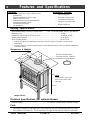
Dimensions & Weight:
Weight: 215 Lbs.
29-1/2"
NOTE:
Measure side, corner, and
back clearances from the
stove top.
5"
The flue collar protrudes 1"
above the stove top. Slide the
included flue ring over the flue.
28"
18"
14-3/4"
Electrical Specifications (for optional blower)
Electrical Rating.........................................................115 Volts, 1.3 Amps, 60 Hz (150 watts on high)
Fuel:
This heater is shipped in natural gas (NG) configuration but may be converted to propane (LP) using
the included LP conversion kit. The sticker on top of the gas control valve will verify the correct fuel.

Installation (for qualified installers only) 7
Travis Industries 93508115 4050113
Installation Warnings:
! Failure to follow all of the requirements may result in property damage, bodily
injury, or even death.
! This heater must be installed by a qualified installer who has gone through a
training program for the installation of direct vent gas appliances.
! This appliance must be installed in accordance with all local codes, if any; if not, in
U.S.A. follow ANSI Z223.1 and NFPA 54(88), in Canada follow B-149.
! In Manufactured or Mobile Homes must conform with: In USA, Manufactured Home
Construction and Safety Standard, Title 24 CFR, Part 3280; In Canada, CSA Z240.4
and Gas-Equipped Recreational Vehicles and Mobile Housing. This appliance may
be installed in Manufactured Housing only after the home is site located.
! This stove is designed to operate on natural gas or propane (LP).
! All exhaust gases must be vented outside the structure of the living-area.
Combustion air is drawn from outside the living-area structure.
! Notify your insurance company before hooking up this stove.
! The requirements listed below are divided into sections. All requirements must be
met simultaneously. The order of installation is not rigid – the qualified installer
should follow the procedure best suited for the installation.
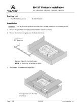
Packing List
• Propane Conversion Kit
• Log Set
• 4” Pipe, 8” Pipe, and 90° Elbow (for gas inlet)
• Glass Latch Tool (to un-latch glass frame)
• Touch-Up Paint
Additional Items Required
• Vent (see “Venting Requirements” for details)
• Gas Line Equipment (shutoff valve, pipe, etc.)
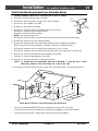
Installation Overview
See "Vent
Requirements"
See "Floor
Protection
Requirements"
See "Gas Line
Installation"
See
"Clearances"

8 Installation (for qualified installers only)
Travis Industries 93508115 4050113
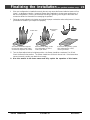
Installation Hints:
• If converting to LP, convert the appliance prior to installation.
• The blower is easiest to install prior to installation. Because the blower is located near the gas inlet
location, we recommend using the included pipe and elbow to route the gas inlet around the blower
position.
• Install the logs last - they are fragile.
• When determining the location of the stove, locate the wall studs (for horizontal penetrations) and
ceiling trusses (for vertical penetrations). You may wish to adjust the stove position slightly to ensure
the vent does not intersect with a framing member.
• Fumes and smoke from the paint curing and oil burning off the steel may occur the first time you start
this heater. This is normal. We recommend you open windows to vent the room.
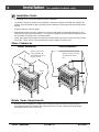
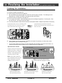
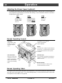
Stove Clearances
9-1/2" Min.
Straight Installations Corner Installations
With this clearance, the vent is
centered 16-1/8" from the
wall.
5" Min.
With this clearance the
vent is centered 6-7/8"
from the back wall, 23-1/2"
from the side wall.
45°
5" Min.
Mobile Home Requirements
• When the stove is installed in a mobile home, it must be bolted to the floor and the appliance
grounded (use the optional blower with a grounded circuit or other suitable grounding method -
current ANSI/NFPA 70 or CSA C22.1).

Installation (for qualified installers only) 9
Travis Industries 93508115 4050113
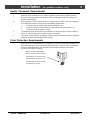
Heater Placement Requirements
• Heater must be installed on a level surface capable of supporting the heater and vent
• Due to the high temperature, the heater should be located out of traffic and away from
furniture and draperies.
? When placed in a location where the floor to ceiling height is under 7 feet, the installation
is considered an alcove and must meet the following requirements:
• The alcove floor to ceiling height must be at least 58” tall
• The alcove must not be more than 45” deep before the ceiling returns to 7’
• The alcove must be at least 47” wide
• The heater must not be placed so the vents below or above the door, along the sides of
heater, or along the back of the heater can become blocked.
• This heater may be placed in a bedroom. Please be aware of the large amount of heat this
appliance produces when determining a location.
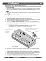
Floor Protection Requirements
• When the stove is installed directly on carpeting, vinyl or other combustible material other
than wood flooring or a high pressure laminate wood floor, the stove must be installed on
a metal or wood protection panel extending the full width and depth of the heater
(Minimum 28” wide by 18” deep).
Make sure these rubber tipped
bolts on each leg contact the floor
(they dampen any noise that may
transmit through the hearth). Do
not adjust with weight on the legs,
the rubber tips may tear.

10 Installation (for qualified installers only)
Travis Industries 93508115 4050113
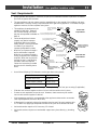
Gas Line Installation
! The gas line must be installed in accordance with all local codes, if any; if not, follow
current ANSI Z223.1 or NFPA 54 in the USA and the current CGA B149 in Canada.
! The heater and gas control valve must be disconnected from the gas supply piping during
any pressure testing of that system at test pressures in excess of 1/2 psig (3.45 kPA). For
pressures under 1/2 psig (3.45 kPA), isolate the gas supply piping by closing the manual
shutoff valve.
• This heater is designed for natural gas but can be converted to propane. Check the
sticker on top of the gas control valve to verify the correct fuel is used (see page 4).
• Leak test all gas line joints and the gas control valve prior to and after starting the heater.
• The gas inlet accepts a 3/8” F.P.T. Fitting
• The location of the gas inlet is shown below
• A manual shutoff valve is required for installation (it must be located within 3’ of the
heater). T-Handle gas cocks are required by Massachusetts in compliance with code 248
CMR.
7-1/8"
Centerline
1-3/4"
9-3/4"
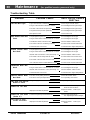
Gas Inlet Pressure
• With the heater off, the inlet pressure must meet the requirements listed in the table
below
? If the pressure is not sufficient, make sure the piping used is large enough and the total
gas load for the residence does not exceed the amount supplied.
? The supply regulator (the regulator that attaches directly to the residence inlet or to the
propane tank) should supply gas at the suggested input pressure listed below. Contact
the local gas supplier if the regulator is at an improper pressure.
Standard Input Pressure
Natural Gas 7” W.C. (1.74 Kpa)
Propane 13” W.C. (2.73 Kpa)

Installation (for qualified installers only) 11
Travis Industries 93508115 4050113
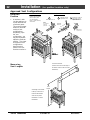
Vent Requirements
! Always maintain the required 1” clearance (air space) to combustible materials to prevent a fire hazard.
Do not fill air spaces with insulation.
! The gas appliance and vent system must be vented directly to the outside of the building, and never
be attached to a chimney serving a separate solid fuel or gas-burning appliance. Each direct vent gas
appliance must use it’s own separate vent system.
• This appliance is equipped only for
altitudes 0-2000 feet. However,
our in-house testing has shown
that the unit operated at altitudes to
8000 ft.
! Failure to adjust the air shutter
properly may lead to improper
combustion which can create a
safety hazard. Consult your dealer
or installer if you suspect an
improperly adjusted air shutter.
• When the vent passes through a
wall, a wall thimble is required.
When the vent passes through a
ceiling, a support box or firestop is
required. When the vent passes
through the roof, a roof flashing
and storm collar are required.
Follow the instructions provided
with the vent for installing these
items.
Use a firestop spacer whenever
passing through a ceiling
Vertical Termination
NOTE: always
use the "high-wind" version (if
applicable)
Use a roof flashing and storm collar
whenever passing through the roof
Use a support box
on exposed vent
Vertical Vent
Requirements
Use a firestop whenever
passing through a wall
Horizontal Termination
Maintain a minimum 1"
clearance from vent to any
combustible.
Minimum
Framing for
wall thimble
Horizontal Vent
Requirements
Minimum framing
for fire stop
Maintain a minimum 1"
clearance from vent to
any combustible
8-5/8"
8-5/8"
• Use of of the following 6-5/8" diameter co-axial gas direct vent systems:
Manuafacturer Series
Simpson Dura-Vent Model GS
Selkirk Hearth Products Direct-Temp
American Metal Products Ameri-Vent
NOTE : Always use the high-wind cap for the type of vent you are using (if applicable)
• Slide the vent sections together and turn 1/4 turn until the sections lock in place.
• Screws are not required to secure the vent. However, three screws may be used to
secure vent sections together if desired.
• High temperature sealant is recommended at the appliance starter section connection
(use high-temperature silicone or Mill-Pac®).
• If disassembly is required, at time of re-assembly check to see if the vent creates a tight
fit. If it does not, apply high temperature sealant to the joints of the affected sections.
• Horizontal sections require a 1/4" rise every 12" of travel
• Horizontal sections require non-combustible support every three feet (e.g.: plumbing
tape)

12 Installation (for qualified installers only)
Travis Industries 93508115 4050113
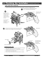
Approved Vent Configurations
Restrictor
Position
• A restrictor is built
into the appliance to
control the flow rate
of exhaust gases.
This ensures proper
flames for the wide
variety of vent
configurations.
Depending upon
the vent
configuration, you
may be required to
adjust the restrictor
position. The charts
for approved vent
configurations
describe which
position the vent
restrictor must be in.
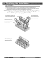
Remove the nuts holding
the stove top in place
(see the illustration
below). Lift the stove top
off the stove.
To Adjust the RestrictorTo Access the Restrictor
NOTE:
The restrictor is
shipped in
position #1.
This restrictor is
in position # 6
Lift the cotter pin out.
a
Slide the restrictor
adjustment rod in.
b
Replace the cotter pin
through the correct
hole on the restrictor
adjustment rod.
c
Restrictor
Positions
# 2
# 4
# 6
# 3
# 5
# 1
3/8" Nutdriver
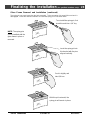
Measuring
Vent Lengths
Vent Horizontal Run
(measure from the closest edge of
the starter section to the end of the
termination)
Vent Height is calculated
to the top of the vent on
horizontal terminations
and to the top of the
termination on vertical
terminations.
Vent
Height

Installation (for qualified installers only) 13
Travis Industries 93508115 4050113
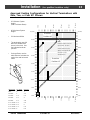
Approved Venting Configurations for Vertical Terminations with
Zero, Two, or Four 45° Elbows
• 10’ Minimum System
Height
(with or without offsets)
• 40’ Maximum System
Height
• 24’ Maximum Offset
• The termination must fall
within the shaded area
shown in the chart. Use
the indicated restrictor
position.
• If using offsets, use the
table below to calculate the
vertical rise and horizontal
offset
Offset
Length
Horizontal
Offset
Vertical
Rise
Offset Length Hor. Offset Vert. Rise
None 5” 1’
1’ Section 1’ 1’ 7”
2’ Section 1’ 9” 2’ 4”
3’ Section 2’ 5” 3’
4’ Section 3’ 2” 3’ 8”
4’ + 1’ Section 3’ 9” 4’ 4”
4’ + 2’ Section 4’ 6” 5’
4’ + 3’ Section 5’ 2” 5’ 9”
4’ + 4’ Section 6’ 6’ 9”
5 feet
10 feet
15 feet
20 feet
25 feet
30 feet
0 feet
40' (max)
5 feet
0 feet
0 feet
5 feet
10 feet
15 feet
20 feet
25 feet
30 feet
40' (max)
Restrictor
Position # 5
NOTE:
Restrictor positions are based
upon lab tests. The ideal
restrictor position may vary
slightly, especially when the
termination is near a
demarkation line.
Restrictor
Position # 6
10 feet
15 feet
20 feet
24 ' (max)
0 feet
5 feet
10 feet
15 feet
20 feet
24 ' (max)
35 feet35 feet

14 Installation (for qualified installers only)
Travis Industries 93508115 4050113
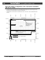
Approved Venting Configurations with a Horizontal Termination
and One 90° Elbow
• If using a Snorkel Termination (14” or 36”) add the snorkel height to the vertical height (snorkel
terminations are used primarily for basement installations).
• The termination must fall within the shaded area shown in the chart. Use the indicated restrictor
position.
5 feet
10 feet
15 feet
19' (max)
0 feet
5 feet
0 feet
0 feet
5 feet
10 feet
15 feet
Restrictor Position # 5
NOTE:
Restrictor positions are based
upon lab tests. The ideal
restrictor position may vary
slightly, especially when the
termination is near a
demarkation line.
Restrictor
Position # 1
10 feet
15 feet
20 feet
24 ' (max)
0 feet
5 feet
10 feet
15 feet
20 feet
24 ' (max)
19' (max)
NOTE:
Horizontal sections require a 1/4"
rise every 12" of travel.
NATURAL GAS: Min. 2' Section Required
PROPANE (LP): Min. 3' Section Required

Installation (for qualified installers only) 15
Travis Industries 93508115 4050113
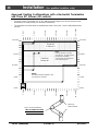
Approved Venting Configurations with a Horizontal Termination
and Two Elbows (one 90° vertical and one 90° or 45° horizontal elbow)
• If using a Snorkel Termination (14” or 36”) add the snorkel height to the vertical height (snorkel
terminations are used primarily for basement installations).
• The termination must fall within the shaded area shown in the chart. Use the indicated restrictor
position.
5 feet
10' (min)
15 feet
19' (max)
0 feet
5 feet
0 feet
0 feet
5 feet
10' (min)
15 feet
Restrictor
Position # 5
NOTE:
Restrictor positions are based upon lab
tests. The ideal restrictor position may vary
slightly, especially when the termination is
near a demarkation line.
Restrictor
Position # 1
10 feet
15 feet
20 feet
24 ' (max)
0 feet
5 feet
10 feet
15 feet
20 feet
24 ' (max)
19' (max)
NOTE:
Horizontal sections require a 1/4"
rise every 12" of travel.
This is considered a horizontal
elbow (it does not matter
whether it turns right or left).
It may be a 90° or 45° elbow.
This is considered a
vertical elbows
Horizontal length (max. 24') is calculated
by adding both lengths of horizontal run
(Horizontal Length = H1 + H2).
H1
H2
NATURAL GAS: Min. 2' Section Required
PROPANE (LP): Min. 3' Section Required

16 Installation (for qualified installers only)
Travis Industries 93508115 4050113
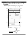
Approved Venting Configurations with a Horizontal Termination
and Three 90° Elbows (all vertical)
• If using a Snorkel Termination (14” or 36”) add the snorkel height to the vertical height (snorkel
terminations are used primarily for basement installations).
• The termination must fall within the shaded area shown in the chart. Use the indicated restrictor
position.
5 feet
10' (min)
15 feet
21' (max)
0 feet
5 feet
0 feet
0 feet
5 feet
10' (min)
15 feet
Restrictor
Position # 5
NOTE:
Restrictor positions are based
upon lab tests. The ideal restrictor
position may vary slightly,
especially when the termination is
near a demarkation line.
Restrictor
Position # 1
10 feet
15 feet
20 feet
24 ' (max)
0 feet
5 feet
10 feet
15 feet
20 feet
24 ' (max)
21' (max)
NOTE:
Horizontal sections require a 1/4"
rise every 12" of travel.
This is a horizontal elbow -
NOT ALLOWED FOR THIS
VENT CONFIGURATION
These are
vertical elbows.

Installation (for qualified installers only) 17
Travis Industries 93508115 4050113
Approved Venting Configurations for Vertical Terminations with
Two 90° Elbows
• The termination must fall within the shaded area shown in the chart. Use the indicated restrictor
position.
5 feet
10' (min)
15 feet
20 feet
25 feet
30 feet
0 feet
40' (max)
5 feet
0 feet
0 feet
5 feet
10' (min)
15 feet
20 feet
25 feet
30 feet
40' (max)
Restrictor
Position # 5
NOTE:
Restrictor positions are
based upon lab tests. The
ideal restrictor position may
vary slightly, especially
when the termination is near
a demarkation line.
Restrictor
Position # 6
10 feet
15 feet
20 feet
24 ' (max)
0 feet
5 feet
10 feet
15 feet
20 feet
24 ' (max)
35 feet35 feet
Restrictor
Position # 1
NOTE:
Horizontal sections require a 1/4"
rise every 12" of travel.
This is a horizontal elbow -
NOT ALLOWED FOR THIS
VENT CONFIGURATION
These are
vertical elbows.

18 Installation (for qualified installers only)
Travis Industries 93508115 4050113
Approved Venting Configurations for Vertical Terminations with
Three 90° Elbows (Two 90° Vertical and One 45° or 90° Horizontal Elbow)
• The termination must fall within the shaded area shown in the chart. Use the indicated restrictor
position.
5 feet
10' (min)
15 feet
20 feet
25 feet
30 feet
0 feet
40' (max)
5 feet
0 feet
0 feet
5 feet
10' (min)
15 feet
20 feet
25 feet
30 feet
40' (max)
Restrictor
Position # 5
NOTE:
Restrictor positions are based
upon lab tests. The ideal
restrictor position may vary
slightly, especially when the
termination is near a demarkation
line.
10 feet
15 feet
20 feet
24 ' (max)
0 feet
5 feet
10 feet
15 feet
20 feet
24 ' (max)
35 feet35 feet
Restrictor
Position # 1
NOTE:
Horizontal sections require a
1/4" rise every 12" of travel.
This is considered a horizontal
elbow (it does not matter
whether it turns right or left).
It may be a 45° or 90° elbow.
This is considered a
vertical elbow
Horizontal length (max. 24') is calculated
by adding both lengths of horizontal run
(Horizontal Length = H1 + H2).
H1
H2
This is considered a
vertical elbow

Installation (for qualified installers only) 19
Travis Industries 93508115 4050113
Vent Termination Requirements (see illustration below)
! Venting terminals shall not be recessed into a wall or siding.
A Minimum 9" clearance from any door or window
B Minimum 12" above any grade, veranda, porch, deck or balcony
C Minimum 12" from outside corner walls
D Minimum 12" from inside corner walls
E Minimum 11" clearance below unventilated soffits or roof surfaces
Minimum 18" clearance below ventilated soffits
Minimum 6" clearance below roof eaves
NOTE: Vinyl surfaces require 24"
11” Min.
6” Min.
Roof
Surface
Roof
Eaves
F Minimum 18" clearance below a veranda, porch, deck or balcony (must have two open sides)
G Minimum 48" clearance from any adjacent building
H Minimum 84" clearance above any grade when adjacent to public walkways or driveways
NOTE: may not be used over a walkway or driveway shared by an adjacent building
I Minimum 48" clearance from any mechanical air supply inlet, 72" for Canada
J Minimum 36" clearance above and 48” below and to the sides of non-mechanical air supply inlet
K Minimum 36" from the area above the meter/regulator (vent outlet)
L Minimum 36" from the meter/regulator (vent outlet)
M Minimum 12” above the roof line (for vertical terminations)
*Note: In Canada the vent termination must be a minimum 2' (.6 M) tall and 2' (.6 M)
above any portion of the roof within 10' (3 M) of the vent.
N Minimum 24” horizontal clearance to any surface (such as an exterior wall) – for vertical terminations
C
B
H
E
G
A
D
F
L
K
J
I
NOTE: Measure clearances to the nearest edge of the exhaust hood.
A
E
E
M
N
• Use the vinyl siding standoff (#1250) when installing on an exterior with vinyl siding.
• Vent termination must not be located where it will become plugged by snow or other material
• These clearances meet UMC-1994 and the CNA/CGA-B149 code standards.

20 Finalizing the Installation (for qualified installers only)
Travis Industries 93508115 4050113
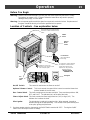
Finalizing the Installation
! Make sure the gas control valve is “OFF” and the heater is cool prior to conducting service.
1 Remove the glass (see page 22)
2 Install the log set and coals (see page 24).
! We recommend you purge the gas line at this time (with the glass removed). This allows gas to be
detected once it enters the firebox, ensuring gas does not build up.
3 Replace and secure the glass (see page 22)
4 Turn on gas to the heater. Leak test all gas joints prior to starting the appliance. Start the pilot. Start
the main burner. Leak test all gas joints again.
5 Check the pilot flame to make sure it looks like the illustration below. Adjust the pilot flame if necessary.
Standard
Screwdriver
The pilot flame must contact the thermocouple and
thermopile (see the illustration below). Adjust the pilot up or
down as necessary.
To adjust the pilot flame, turn this screw (NOTE: if totally
unscrewed gas will come out of this port). Clockwise
lowers the flame while counter-clockwise raises it.
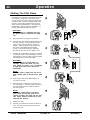
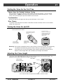
6 Let the heater burn for thirty minutes. Adjust the air shutter, if necessary, to achieve the correct
looking flame (see the illustration below).
• The air shutter adjusts the amount of air that mixes with the gas before it exits the burner holes. It is
used to fine-tune the flame for differences in altitude and vent configuration.
Gas Control Valve
NOTE: If the air shutter is all the way
open, yet the flames remain sooty, shut
off gas to the fireplace and contact a
qualified gas service technician.
Correct
Flames should be blue at the
base, yellow-orange on the top.
If the flames are over 14" tall or sooty on
the ends, open the air shutter.
Not Enough Air
If the flames are all blue and
short, close the air shutter.
Too Much Air
NOTE: The logs must be installed correctly to
monitor the flame while adjusting the air shutter.
Air Shutter Control
Pushing to the left gives the flame less air
(making it more orange). Pushing to the
right gives the flame more air, making it
more blue. For fine adjustments use a
screwdriver to tap the air shutter.
ADJUSTING THE AIR SHUTTER
Page is loading ...
Page is loading ...
Page is loading ...
Page is loading ...
Page is loading ...
Page is loading ...
Page is loading ...
Page is loading ...
Page is loading ...
Page is loading ...
Page is loading ...
Page is loading ...
Page is loading ...
Page is loading ...
Page is loading ...
Page is loading ...
Page is loading ...
Page is loading ...
Page is loading ...
Page is loading ...
Page is loading ...
Page is loading ...
-
 1
1
-
 2
2
-
 3
3
-
 4
4
-
 5
5
-
 6
6
-
 7
7
-
 8
8
-
 9
9
-
 10
10
-
 11
11
-
 12
12
-
 13
13
-
 14
14
-
 15
15
-
 16
16
-
 17
17
-
 18
18
-
 19
19
-
 20
20
-
 21
21
-
 22
22
-
 23
23
-
 24
24
-
 25
25
-
 26
26
-
 27
27
-
 28
28
-
 29
29
-
 30
30
-
 31
31
-
 32
32
-
 33
33
-
 34
34
-
 35
35
-
 36
36
-
 37
37
-
 38
38
-
 39
39
-
 40
40
-
 41
41
-
 42
42


Avalon Stoves Direct Vent Freestanding Stove User manual
- Category
- Cookers
- Type
- User manual
- This manual is also suitable for
Ask a question and I''ll find the answer in the document
Finding information in a document is now easier with AI
Related papers
-
 Avalon Direct Vent Freestanding Stove User manual
-
 Avalon Stoves 864 User manual
-
 Avalon Stoves 21 DV Fireplace User manual
-
 Avalon Avalon Olympic User manual
-
 Avalon Stoves 1250 User manual
-
 Avalon Rainier 990 User manual
-
 Avalon Stoves Arbor User manual
-
 Avalon Stoves DVL Insert EF II User manual
-
 Avalon Avalon Olympic User manual
-
 Avalon Stoves Arbor PS User manual


Other documents
-
Travis Industries Avalon Cedar User manual
-
Lopi Spirit Bay B-Vent Insert Owner's manual
-
-
-
-
FireplaceXtrordinair 864 HH User manual
-
North Star 864 HH User manual
-
-
Harman Stove Company FireLuxe User manual
-