Page is loading ...

Manufacturer reserves the right to discontinue, or change at any time, specifications or designs without notice and without incurring obligations.
PC 111 Catalog No. 535-034 Printed in U.S.A. Form 50TJ-17SI Pg 1 2-01 Replaces: 50TJ-14SI
Book 1
Ta b 1 b
Installation, Start-Up and
Service Instructions
CONTENTS
Page
SAFETY CONSIDERATIONS
. . . . . . . . . . . . . . . . . . . . . . . . .1
INSTALLATION
. . . . . . . . . . . . . . . . . . . . . . . . . . . . . . . . . . . 1-18
Step 1 — Provide Unit Support
. . . . . . . . . . . . . . . . . . . . . .1
• ROOF CURB
• ALTERNATE UNIT SUPPORT
Step 2 — Rig and Place Unit
. . . . . . . . . . . . . . . . . . . . . . . . .1
• POSITIONING
• ROOF MOUNT
Step 3 — Field Fabricate Ductwork
. . . . . . . . . . . . . . . . . .7
Step 4 — Make Unit Duct Connections
. . . . . . . . . . . . . . .7
Step 5 — Trap Condensate Drain
. . . . . . . . . . . . . . . . . . . .7
Step 6 — Make Electrical Connections
. . . . . . . . . . . . . .8
• FIELD POWER SUPPLY
• FIELD CONTROL WIRING
• OPTIONAL NON-FUSED DISCONNECT
• OPTIONAL CONVENIENCE OUTLET
Step 7 — Make Outdoor-Air Inlet
Adjustments
. . . . . . . . . . . . . . . . . . . . . . . . . . . . . . . . . . . . . . .11
• MANUAL OUTDOOR-AIR DAMPER
• OPTIONAL ECONOMI$ER
Step 8 — Install Outdoor-Air Hood
. . . . . . . . . . . . . . . . . .12
Step 9 — Install All Accessories
. . . . . . . . . . . . . . . . . . . .15
• MOTORMASTER® I CONTROL INSTALLATION
• MOTORMASTER III CONTROL INSTALLATION
Step 10 — Install Humidistat for Optional
MoistureMiser Dehumidification Package
. . . . . . . . .16
START-UP
. . . . . . . . . . . . . . . . . . . . . . . . . . . . . . . . . . . . . . . 18-24
SERVICE
. . . . . . . . . . . . . . . . . . . . . . . . . . . . . . . . . . . . . . . . 24-31
TROUBLESHOOTING
. . . . . . . . . . . . . . . . . . . . . . . . . . . . 32,33
START-UP CHECKLIST
. . . . . . . . . . . . . . . . . . . . . . . . . . CL-1
SAFETY CONSIDERATIONS
Installation and servicing air-conditioning equipment can be
hazardous due to system pressure and electrical components.
Only trained and qualified service personnel should install, re-
pair, or service air-conditioning equipment.
Untrained personnel can perform basic maintenance func-
tions of cleaning coils and filters and replacing filters. All other
operations should be performed by trained service personnel.
When working on air-conditioning equipment, observe precau-
tions in the literature, tags and labels attached to the unit, and
other safety precautions that may apply.
Follow all safety codes. Wear safety glasses and work
gloves. Use quenching cloth for unbrazing operations. Have
fire extinguishers available for all brazing operations.
INSTALLATION
Step 1 — Provide Unit Support
ROOF CURB — Assemble and install accessory roof curb or
horizontal adapter roof curb in accordance with instructions
shipped with the curb or horizontal adapter. Accessory roof
curb and horizontal adapter roof curb and information required
to field fabricate a roof curb or horizontal adapter roof curb are
shown in Fig. 1 and 2. Install insulation, cant strips, roofing,
and counter flashing as shown. Ductwork can be secured to
roof curb before unit is set in place.
Curb or adapter roof curb should be level. This is necessary
to permit unit drain to function properly. Unit leveling toler-
ance is
±
1
/
16
in. per linear ft in any direction. Refer to Accesso-
ry Roof Curb or Horizontal Adapter Roof Curb Installation In-
structions for additional information as required.
ALTERNATE UNIT SUPPORT — When the curb or adapter
cannot be used, support unit with sleepers using unit curb or
adapter support area. If sleepers cannot be used, support long
sides of unit with a minimum of 3 equally spaced 4-in. x 4-in.
pads on each side.
Step 2 — Rig and Place Unit —
Inspect unit for
transportation damage. File any claim with transportation
agency. Keep unit upright, and do not drop. Use spreader bars
over unit to prevent sling or cable damage. Rollers may be used
to move unit across a roof. Level by using unit frame as a refer-
ence; leveling tolerance is
±
1
/
16
in. per linear ft in any direc-
tion. See Fig. 3 for additional information. Unit weight is
shown in Table 1.
Four lifting holes are provided in ends of unit base rails as
shown in Fig. 3. Refer to rigging instructions on unit.
POSITIONING — Provide clearance around and above unit
for airflow, safety, and service access (Fig. 4 and 5).
Do not install unit in an indoor location. Do not locate air in-
lets near exhaust vents or other sources of contaminated air.
Although unit is weatherproof, guard against water from
higher level runoff and overhangs.
ROOF MOUNT — Check building codes for weight distribu-
tion requirements.
Before performing service or maintenance operations on
unit, turn off main power switch to unit. Electrical shock
could cause personal injury.
IMPORTANT: Units have high ambient operating lim-
its. If limits are exceeded, the unit will automatically
lock the compressor out of operation. Manual reset will
be required to restart the compressor.
IMPORTANT: The gasketing of the unit to the roof curb
or adapter roof curb is critical for a leak-proof seal.
Install gasket supplied with the roof curb or adapter roof
curb as shown in Fig. 1. Improperly applied gasket can
result in air leaks and poor unit performance.
50TJ016-028
Single-Package Rooftop Units
Electric Cooling with Electric Heat Option

2
NOTES:
1. Roof curb accessory is shipped disassembled.
2. Insulated panels: 1
″
thick neoprene coated 1
1
/
2
lb density.
3. Dimensions in ( ) are in millimeters.
4. Direction of airflow.
5. Roof curb: 16 ga. (VA03-56) stl.
6.
A 90 degree elbow must be installed on the supply ductwork
below the unit discharge for units equipped with electric
heaters.
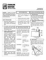
NOTE: To prevent the hazard of stagnant water build-up in the drain
pan of the indoor section, unit can only be pitched as shown.
DIMENSIONS* (degrees and inches)
UNIT
AB
Deg.in.Deg.in.
ALL
.28 .45 .28 .43
PKG. NO. REF. CURB HEIGHT DESCRIPTION
CRRFCURB010A00 1
′
-2
″
(305) Standard Curb 14
″
High
CRRFCURB011A00 2
′
-0
″
(610) Standard Curb for Units Requiring High Installation
CRRFCURB012A00 2
′
-0
″
(610) Side Supply and Return Curb for High Installation
Fig. 1 — Roof Curb Details

3
NOTE: For preassembled horizontal adapter roof curb part no.
CRRFCURB013A00, the accessory kit includes a factory-designed,
high-static, transition duct. For horizontal curb part no.
CRRFCURB012A00, a field-supplied transition duct is required.
Fig. 2 — Horizontal Adapter Roof Curb
and Roof Curb
NOTES:
1. Dimensions in ( ) are in millimeters.
2. Refer to Fig. 4 and 5 for unit operating weights.
3. Remove boards at ends of unit and runners prior to rigging.
4. Rig by inserting hooks into unit base rails as shown. Use corner
post from packaging to protect coil from damage. Use bumper
boards for spreader bars.
5. Weights do not include optional EconoMi$er. See Fig. 4 and 5 for
EconoMi$er weight. See Table 1 for MoistureMiser weight.
6. Weights given are for aluminum evaporator and condenser coil
plate fins.
Fig. 3 — Rigging Details
UNIT
50TJ
MAXIMUM
SHIPPING WEIGHT
DIMENSIONS
AB
Lb Kg Ft-in. mm Ft-in. mm
016
1550 703 6-11
1
/
2
2121 4- 0 1219
020
1650 748 6-11
1
/
2
2121 3-10 1168
024
1700 771 6-11
1
/
2
2121 3- 7 1092
028
1850 839 6-11
1
/
2
2121 3- 5 1041
All panels must be in place when rigging.

4
POWER EXHAUST/BAROMETRIC RELIEF
(ACCESSORY ONLY)
Fig. 4 — Base Unit Dimensions, 50TJ016,020
UNIT
STD UNIT
WEIGHT
ECONOMI$ER
WEIGHT
CORNER
(A)
CORNER
(B)
CORNER
(C)
CORNER
(D)
DIM A DIM B DIM C
Lb Kg Lb Kg Lb Kg Lb Kg Lb Kg Lb Kg Ft-in. mm Ft-in. mm Ft-in. mm
50TJ016
1550 703 80 36.3 391 177 365 166 384 174 410 186 3-5 1041 3-6 1067 1-10 559
50TJ020
1650 748 80 36.3 399 181 384 174 402 182 439 199 3-4 1016 3-6 1067 1- 8 508
NOTES:
1. Refer to print for roof curb accessory dimensions.
2. Dimensions in [ ] are in millimeters.
3. Center of gravity.
4. Direction of airflow.
5. Ductwork to be attached to accessory roof curb only.
6. Minimum clearance:
•
Rear: 7
′
-0
″
(2134) for coil removal. This dimension can be
reduced to 4
′
-0
″
(1219) if conditions permit coil removal from the
top.
•
Left side: 4
′
-0
″
(1219) for proper condenser coil airflow.
•
Front: 4
′
-0
″
(1219) for control box access.
•
Right side: 4
′
-0
″
(1219) for proper operation of damper and
power exhaust if so equipped.
•
Top: 6
′
-0
″
(1829) to assure proper condenser fan operation.
•
Local codees or jurisdiction may prevail.
7. With the exception of clearance for the condenser coil and the
damper/power exhaust as stated in Note #6, a removable fence or
barricade requires no clearance.
8. Dimensions are from outside of corner post. Allow 0
′
-
5
/
16
″
(8) on
each side for top cover drip edge.
9. See drawing 50TJ500352 for service option details.

5
POWER EXHAUST/BAROMETRIC RELIEF
(ACCESSORY ONLY)
Fig. 5 — Base Unit Dimensions, 50TJ024,028
UNIT
STD UNIT
WEIGHT
ECONOMI$ER
WEIGHT
CORNER
(A)
CORNER
(B)
CORNER
(C)
CORNER
(D)
DIM ADIM BDIM C
Lb Kg Lb Kg Lb Kg Lb Kg Lb Kg Lb Kg Ft-in. mm Ft-in. mm Ft-in. mm
50TJ024
1700 771 80 36.3 419 190 394 179 425 193 463 210 3-4 1016 3-5 1041 1-8 508
50TJ028
1850 839 80 36.3 428 194 412 187 511 232 499 226 3-2 965 3-7 1092 1-8 508
NOTES:
1. Refer to print for roof curb accessory dimensions.
2. Dimensions in [ ] are in millimeters.
3. Center of gravity.
4. Direction of airflow.
5. Ductwork to be attached to accessory roof curb only.
6. Minimum clearance:
•
Rear: 7
′
-0
″
(2134) for coil removal. This dimension can be
reduced to 4
′
-0
″
(1219) if conditions permit coil removal from the
top.
•
Left side: 4
′
-0
″
(1219) for proper condenser coil airflow.
•
Front: 4
′
-0
″
(1219) for control box access.
•
Right side: 4
′
-0
″
(1219) for proper operation of damper and
power exhaust if so equipped.
•
Top : 6
′
-0
″
(1829) to assure proper condenser fan operation.
•
Local codees or jurisdiction may prevail.
7. With the exception of clearance for the condenser coil and the
damper/power exhaust as stated in Note #6, a removable fence or
barricade requires no clearance.
8. Dimensions are from outside of corner post. Allow 0
′
-
5
/
16
″
(8) on
each side for top cover drip edge.
9. See drawing 50TJ500352 for service option details.

6
Table 1 — Physical Data
LEGEND
*Circuit 1 uses the lower portion of condenser coil and lower portion of evap-
orator coils; and Circuit 2 uses the upper portion of both coils.
†The 50TJ028 units requires 2-in. industrial-grade filters capable of handling
face velocities of up to 625 ft/min (such as American Air Filter no. 5700 or
equivalent).
NOTE: The 50TJ016-028 units have a low-pressure switch (standard) located
on the suction side.
UNIT 50TJ
016
020 024 028
208/230, 460 v 575 v
NOMINAL CAPACITY (tons) 15 18 20 25
OPERATING WEIGHT 1550 1650 1700 1850
EconoMi$er 80
80 80 80
MoistureMiser Dehumidification
Package
40
40 40 40
COMPRESSOR/MANUFACTURER Scroll, Copeland
Quantity...Model (Ckt 1, Ckt 2)
2...ZR94KC
50, 50
2
81, 81
1...ZR108KC,
1...ZR94KC
1...ZR125KC,
1...ZR108KC
1...ZR16M3,
1...ZR125KC
Capacity Stages (%) 55, 45 55, 45 60, 40
Number of Refrigerant Circuits 22 2
Oil (oz) (Ckt 1, Ckt 2) 106, 81 106,106 136, 106
REFRIGERANT TYPE R-22
Expansion Device TXV
Operating Charge (lb-oz)
Circuit 1* 10-10
10-10
15-5 16-0 20-13
Circuit 2 12-3 13-6 13- 0
CONDENSER COIL Cross-Hatched
3
/
8
-in. Copper Tubes, Aluminum Lanced,
Aluminum Pre-Coated, or Copper Plate Fins
Rows...Fins/in. 2...17
21.7
3...15 3...15 4...15
Total Face Area (sq ft) 21.7 21.7 21.7
CONDENSER FAN Propeller Type
Nominal Cfm 10,500 10,500 14,200 14,200
Quantity...Diameter (in.) 3...22 3...22 2...30 2...30
Motor Hp...Rpm
1
/
2
...1050
1
/
2
...1050 1...1075 1...1075
Watts Input (Total) 1100 1100 3400 3400
EVAPORATOR COIL Cross-Hatched
3
/
8
-in. Copper Tubes, Aluminum Lanced or
Copper Plate Fins, Face Split
Rows...Fins/in. 2...17 3...15 3...15 4...15
Total Face Area (sq ft) 17.5 17.5 17.5 17.5
EVAPORATOR FAN Centrifugal Type
Quantity...Size (in.) 2...10 x 10 2...10 x 10 2...12 x 12 2...12 x 12 2...12 x 12
Type Drive Belt Belt Belt Belt Belt
Nominal Cfm 6000 6000 7200 8000 10,000
Motor Hp 3.7 3.0 5 7.5 10
Motor Nominal Rpm 1725 1725 1745 1745 1740
Maximum Continuous Bhp 4.25 3.45 5.90
8.7 [208/230, 575 v]
9.5 [460 v]
10.2 [208/230, 575 v]
11.8 [380, 460 v]
Motor Frame Size 56H 56H 184T 213T 215T
Nominal Rpm High/Low ——— — —
Fan r/s Range Low-Medium Static 891-1179 1159-1429 910-1095 1002-1225 1066-1283
High Static 1227-1550 — 1069-1287 1193-1458 1332-1550
Motor Bearing Type Ball Ball Ball Ball Ball
Maximum Allowable Rpm 1550 1550 1550 1550 1550
Motor Pulley Pitch Diameter Low-Medium Static 3.1/4.1 4.3/5.3 4.9/5.9 5.4/6.6 4.9/5.9
Min/Max (in.) High Static 3.7/4.7 — 4.9/5.9 5.4/6.6 4.9/5.9
Nominal Motor Shaft Diameter (in.)
7
/
8
7
/
8
1
1
/
8
1
3
/
8
1
3
/
8
Fan Pulley Pitch Diameter (in.) Low-Medium Static 6.0 6.4 9.4 9.4 8.0
High Static 5.2 — 8.0 7.9 6.4
Nominal Fan Shaft Diameter (in.) 1
3
/
16
1
3
/
16
1
7
/
16
1
7
/
16
1
7
/
16
Belt, Quantity...Type...Length (in.) Low-Medium Static 1...BX...42 1...BX...45 1...BX...50 1...BX...53 2...BX...50
High Static 1...BX...42 — 1...BX...48 1...BX...50 2...BX...47
Pulley Center Line Distance (in.) 13.5-15.5 13.5-15.5 13.3-14.8 14.6-15.4 14.6-15.4
Speed Change per Full Turn of
Movable Pulley Flange (rpm)
Low-Medium Static 48 44 37 37 36
High Static 55 — 34 44 45
Movable Pulley Maximum Full Turns
From Closed Position 666 6 6
Factory Speed 3.5 3.5 3.5 3.5 3.5
Factory Speed Setting (rpm Low-Medium Static 1035 1296 1002 1120 1182
High Static 1389 — 1178 1328 1470
Fan Shaft Diameter at Pulley (in.) 1
3
/
16
1
3
/
16
1
7
/
16
1
7
/
16
1
7
/
16
HIGH-PRESSURE SWITCH (psig)
Cutout 426
Reset (Auto) 320
LOW-PRESSURE SWITCH (psig)
Cutout 27
Reset (Auto) 44
FREEZE PROTECTION THERMOSTAT (F)
Opens 30
±
5
Closes 45
±
5
OUTDOOR-AIR INLET SCREENS Cleanable
Quantity...Size (in.) 2...20 x 25 x 1
1...20 x 20 x 1
RETURN-AIR FILTERS Throwaway†
Quantity...Size (in.) 4...20 x 20 x 2
4...16 x 20 x 2
POWER EXHAUST
1
/
2
Hp, 208/230-460 v Motor Direct Drive, Propeller-Fan (Factory-Wired for 460 v)
Bhp — Brake Horsepower
TXV — Thermostatic Expansion Valve

7
Step 3 — Field Fabricate Ductwork —
Secure all
ducts to building structure. Use flexible duct connectors be-
tween unit and ducts as required. Insulate and weatherproof all
external ductwork, joints, and roof openings with counter
flashing and mastic in accordance with applicable codes.
Ducts passing through an unconditioned space must be in-
sulated and covered with a vapor barrier.
The 50TJ units with electric heat require a 1-in. clearance
for the first 24 in. of ductwork.
Outlet grilles must not lie directly below unit discharge.
NOTE: A 90-degree elbow must be provided in the ductwork
to comply with UL (Underwriters’ Laboratories) codes for use
with electric heat.
Step 4 — Make Unit Duct Connections —
Unit
is shipped for through-the-bottom duct connections. Ductwork
openings are shown in Fig. 6. Field-fabricated concentric duct-
work may be connected as shown in Fig. 7 and 8. Attach all
ductwork to roof curb and roof curb basepans. Refer to installa-
tion instructions shipped with accessory roof curb for more
information.
Step 5 — Trap Condensate Drain —
See Fig. 4, 5,
and 9 for drain location. Plug is provided in drain hole and
must be removed when unit is operating. One
3
/
4
-in. half-
coupling is provided inside unit evaporator section for conden-
sate drain connection. An 8
1
/
2
in. x
3
/
4
-in. diameter nipple and a
2-in. x
3
/
4
-in. diameter pipe nipple are coupled to standard
3
/
4
-in. diameter elbows to provide a straight path down through
holes in unit base rails (see Fig. 10). A trap at least 4-in. deep
must be used.
For vertical supply and return units, tools or parts could
drop into ductwork and cause an injury. Install a 90 degree
turn in the return ductwork between the unit and the condi-
tioned space. If a 90 degree elbow cannot be installed, then
a grille of sufficient strength and density should be installed
to prevent objects from falling into the conditioned space.
Due to electric heater, supply duct will require 90 degree
elbow.
NOTE: Do not drill in this area; damage to basepan may result in
water leak.
Fig. 6 — Air Distribution — Thru-the-Bottom
(50TJ020-028 Shown)
NOTE: Do not drill in this area; damage to basepan may result in
water leak.
Fig. 7 — Concentric Duct Air Distribution
(50TJ020-028 Shown)
3/4" FPT DRAIN
CONNECTION
1-3/8"
DRAIN HOLES
Shaded area indicates block-off panels.
NOTE: Dimensions A, A
′,
and B, B
′
are obtained from field-supplied
ceiling diffuser.
Fig. 8 — Concentric Duct Details
Fig. 9 — Condensate Drain Details
(50TJ016,020 Shown)

8
Step 6 — Make Electrical Connections
FIELD POWER SUPPLY — Unit is factory wired for volt-
age shown on nameplate.
When installing units, provide a disconnect, per NEC
(National Electrical Code) requirements, of adequate size
(Table 2).
All field wiring must comply with NEC and local
requirements.
Route power lines through control box access panel or unit
basepan (Fig. 4 and 5) to connections as shown on unit wiring
diagram and Fig. 11.
Operating voltage to compressor must be within voltage
range indicated on unit nameplate. On 3-phase units, voltages
between phases must be balanced within 2% and the current
must be balanced within 10%.
Use the following formula to determine the percentage of
voltage imbalance.
Percentage of Voltage Imbalance
EXAMPLE: Supply voltage is 460-3-60.
AB = 452 v
BC = 464 v
AC = 455 v
Determine maximum deviation from average voltage:
(AB) 457 – 452 = 5 v
(BC) 464 – 457 = 7 v
(AC) 457 – 455 = 2 v
Maximum deviation is 7 v.
Determine percent voltage imbalance:
= 1.53%
This amount of phase imbalance is satisfactory as it is be-
low the maximum allowable 2%.
Unit failure as a result of operation on improper line voltage
or excessive phase imbalance constitutes abuse and may cause
damage to electrical components.
FIELD CONTROL WIRING — Install a Carrier-approved
accessory thermostat assembly according to the installation in-
structions included with the accessory. Locate thermostat as-
sembly on a solid wall in the conditioned space to sense aver-
age temperature.
Route thermostat cable or equivalent single leads of no. 18
AWG (American Wire Gage) colored wire from subbase termi-
nals through conduit in unit to low-voltage connections as
shown on unit label wiring diagram and in Fig. 12.
NOTE: For wire runs up to 50 ft, use no. 18 AWG insulated
wire (35 C minimum). For 50 to 75 ft, use no. 16 AWG insu-
lated wire (35 C minimum). For over 75 ft, use no. 14 AWG
insulated wire (35 C minimum). All wire larger than no. 18
AWG cannot be directly connected to the thermostat and will
require a junction box and splice at the thermostat.
Set heat anticipator settings as indicated in Table 3. Settings
may be changed slightly to provide a greater degree of comfort
for a particular installation.
The correct power phasing is critical in the operation of the
scroll compressors. An incorrect phasing will cause the
compressor to rotate in the wrong direction. This may lead
to premature compressor failure.
= 100 x
max voltage deviation from average voltage
average voltage
Average Voltage =
455 + 464 + 455
3
=
1371
3
= 457
Percentage of Voltage Imbalance = 100 x
7
457
IMPORTANT: If the supply voltage phase imbalance is
more than 2%, contact your local electric utility com-
pany immediately.
Fig. 10 — Make Electrical Connections
TB1 MAXIMUM WIRE SIZE
LEGEND
Fig. 11 — Field Power Wiring Connections
UNIT
50TJ
VOLTAGE
208/230,380 460 575
All
350 kcmil 2/0 2/0
EQUIP —
Equipment
GND —
Ground
kcmil —
Thousand Circular Mils
NEC —
National Electrical Code
TB —
Terminal Block
RH
RC
Y1 Y2
W1
W2
GC
X
L
X
C
G
W2
W1Y2
Y1
R
REMOVABLE JUMPER
RED
BLU
PNK
ORN
VIO
BLK
BRN
WHT
THERMOSTAT ASSEMBLY
UNIT LOW-VOLTAGE CONNECTIONS
Fig. 12 — Field Control Thermostat Wiring

9
Table 2 — Electrical Data
UNIT
50TJ
NOMINAL
VOLTAGE
(3 Ph,
60 Hz)
VOLTAGE
RANGE
COMPRESSOR
OFM IFM
POWER
EXHAUST
ELECTRIC
HEAT*
POWER
SUPPLY
No. 1 No. 2
Min Max RLA LRA RLA LRA Qty Hp FLA (ea) Hp FLA FLA LRA kW FLA MCA MOCP†
016
(15 Tons)
208/230 187 253 28.8 195 28.8 195 3 0.5 1.7 3.7 10.5/11.0
—— — — 81/81 100/100
4.6 18.8 ——85/86 110/110
——26/34 71/82 102/116 110/125
4.6 18.8 26/34 71/82 108/122 110/125
——42/56 117/135 159/149 175/175
4.6 18.8 42/56 117/135 165/155 175/175
——56/75** 156/180 169/194 200/225
4.6 18.8 56/75** 156/180 175/200 200/225
380 342 418 15.0 123 15.0 123 3 0.5 1.7 3.7 3.9
—— — — 43 50
2.3 6.0 —— 45 60
—— 20 30 43 50
2.3 6.0 20 30 46 60
—— 35 52 70 80
2.3 6.0 35 52 73 80
460 414 508 14.7 95 14.7 95 3 0.5 0.8 3.7 4.8
—— — — 40 50
2.3 6.0 —— 43 50
—— 32 39 55 60
2.3 6.0 32 39 58 60
—— 55 66 72 80
2.3 6.0 55 66 75 80
—— 80** 96 102 110
2.3 6.0 80** 96 105 110
575 518 633 10.8 80 10.8 80 3 0.5 0.75 3.0 3.9
—— — — 30 40
2.1 4.8 —— 32 40
—— 50** 48 67 70
2.1 4.8 50** 48 70 70
020
(18 Tons)
208/230 187 253 30.1 225 28.8 195 3 0.5 1.7 5.0 15.8/15.8
—— — — 87/87 110/110
4.6 18.8 ——92/92 110/110
——26/34 71/82 109/122 110/125
4.6 18.8 26/34 71/82 114/128 125/150
——42/56 117/135 166/155 175/175
4.8 18.8 42/56 117/135 172/161 175/175
——56/75** 156/180 176/200 200/225
4.6 18.8 56/75** 156/180 182/206 200/225
460 414 508 15.5 114 14.7 95 3 0.5 0.8 5.0 7.9
—— — — 44 50
2.3 6.0 —— 47 60
—— 32 39 59 60
2.3 6.0 32 39 61 70
—— 55 66 76 90
2.3 6.0 55 66 79 90
—— 80** 96 106 125
2.3 6.0 80** 96 109 125
575 518 633 12.1 80 10.8 80 3 0.5 0.75 5.0 6.0
—— — — 34 40
2.1 4.8 —— 36 40
024
(20 Tons)
208/230 187 253 37.8 239 30.1 225 2 1 6.6 7.5 25.0/25.0
—— — — 116/116 150/150
4.6 18.8 ——120/120 150/150
——26/34 71/82 120/134 150/150
4.6 18.8 26/34 71/82 126/140 150/150
——42/56 117/135 178/166 200/175
4.6 18.8 42/56 117/135 183/172 200/175
——56/75** 156/180 187/211 200/225
4.6 18.8 56/75** 156/180 193/217 200/225
380 342 418 21.2 145 16.7 140 2 1 3.9 7.5 15.0
—— — — 66 80
2.3 6.0 —— 68 80
—— 20 30 66 80
2.3 6.0 20 30 68 80
—— 35 52 84 90
2.3 6.0 35 52 87 90
460 414 508 17.2 125 15.5 114 2 1 3.3 7.5 13.0
—— — — 57 70
2.3 6.0 —— 59 70
—— 32 39 65 70
2.3 6.0 32 39 68 70
—— 55 66 82 90
2.3 6.0 55 66 85 90
—— 80** 96 112 125
2.3 6.0 80** 96 115 125
575 518 633 12.4 80 12.1 80 2 1 3.4 7.5 10.0
—— — — 44 50
2.1 4.8 —— 46 50

10
Table 2 — Electrical Data (cont)
LEGEND
*Heater capacity (kW) is based on heater voltage of 208 v, 240 v,
380 v, 480 v, and 575 v. Heaters are rated at 240 v, 380 v, 480 v, or
600 v. If power distribution voltage to unit varies from rated heater
voltage, heater kW will vary accordingly.
†Fuse or HACR circuit breaker.
**Heaters are field installed only.
NOTES:
1. In compliance with NEC requirements for multimotor and combi-
nation load equipment (refer to NEC Articles 430 and 440), the
overcurrent protective device for the unit shall be fuse or HACR
breaker. Canadian units may be fuse or circuit breaker.
2.
Unbalanced 3-Phase Supply Voltage
Never operate a motor where a phase imbalance in supply volt-
age is greater than 2%.
Use the following formula to determine
the percent of voltage imbalance.
% Voltage Imbalance
Example: Supply voltage is 460-3-60.
AB = 452 v
BC = 464 v
AC = 455 v
= 457
Determine maximum deviation from average voltage.
(AB) 457 – 452 = 5 v
(BC) 464 – 457 = 7 v
(AC) 457 – 455 = 2 v
Maximum deviation is 7 v.
Determine percent of voltage imbalance.
% Voltage Imbalance = 100 x
= 1.53%
This amount of phase imbalance is satisfactory as it is below the
maximum allowable 2%.
3. MCA calculation for units with electric heaters over 50 kW =
(1.25 x IFM amps) + (1.00 x heater FLA).
UNIT
50TJ
NOMINAL
VOLTAGE
(3 Ph,
60 Hz)
VOLTAGE
RANGE
COMPRESSOR
OFM IFM
POWER
EXHAUST
ELECTRIC
HEAT*
POWER
SUPPLY
No. 1 No. 2
Min Max RLA LRA RLA LRA Qty Hp FLA (ea) Hp FLA FLA LRA kW FLA MCA MOCP†
028
(25 Tons)
208/230 187 253 41.0 350 37.8 239 2 1 6.6 10.0 28.0/28.0
—— — — 130/130 150/150
4.6 18.8 ——135/135 175/175
——26/34 71/82 130/138 150/150
4.6 18.8 26/34 71/82 135/143 175/175
——42/56 117/135 181/170 200/175
4.6 18.8 42/56 117/135 187/176 200/200
— - 56/75** 156/180 191/215 200/225
4.6 18.8 56/75** 156/180 197/221 200/225
380 342 418 21.8 151 21.2 145 2 1 3.9 10.0 17.0
—— — — 73 90
2.3 6.0 —— 76 90
—— 20 30 73 90
2.3 6.0 20 30 76 90
—— 35 52 87 90
2.3 6.0 35 52 90 90
460 414 508 21.8 158 17.2 125 2 1 2.8 10.0 14.6
—— — — 66 80
2.3 6.0 —— 68 80
—— 32 39 67 80
2.3 6.0 32 39 70 80
—— 55 66 84 90
2.3 6.0 55 66 87 100
—— 80** 96 114 125
2.3 6.0 80** 96 117 125
575 518 633 17.3 125 12.4 80 2 1 3.4 10.0 13.0
—— — — 54 70
2.1 4.8 —— 56 70
FLA —
Full Load Amps
HACR —
Heating, Air Conditioning and Refrigeration
IFM —
Indoor (Evaporator) Fan Motor
LRA —
Locked Rotor Amps
MCA —
Minimum Circuit Amps
MOCP—
Maximum Overcurrent Protection
NEC —
National Electrical Code
OFM —
Outdoor (Condenser) Fan Motor
RLA —
Rated Load Amps
= 100 x
max voltage deviation from average voltage
average voltage
Average Voltage =
452 + 464 + 455
3
=
1371
3
IMPORTANT: If the supply voltage phase imbalance is
more than 2%, contact your local electric utility company
immediately.
7
457

11
OPTIONAL NON-FUSED DISCONNECT — On units with
the optional non-fused disconnect, incoming power will be
wired into the disconnect switch. Refer to Fig. 13 for wiring
for 100 and 200 amp disconnect switches. Units with an
MOCP under 100 will use the 100 amp disconnect switch.
Units with an MOCP over 100 will use the 200 amp discon-
nect switch. Refer to the applicable disconnect wiring diagram.
To prevent breakage during shipping, the disconnect han-
dle and shaft are shipped and packaged inside the unit control
box. Install the disconnect handle before unit operation. To in-
stall the handle and shaft, perform the following procedure:
1. Open the control box door and remove the handle and
shaft from shipping location.
2. Loosen the Allen bolt located on the disconnect switch.
The bolt is located on the square hole and is used to hold
the shaft in place. The shaft cannot be inserted until the
Allen bolt is moved.
3. Insert the disconnect shaft into the square hole on the dis-
connect switch. The end of the shaft is specially cut and
the shaft can only be inserted in the correct orientation.
4. Tighten the Allen bolt to lock the shaft into position.
5. Close the control box door.
6. Attach the handle to the external access door with the two
screws provided. When the handle is in the ON position,
the handle will be vertical. When the handle is in the OFF
position, the handle will be horizontal.
7. Turn the handle to the OFF position and close the door.
The handle should fit over the end of the shaft when the
door is closed.
8. The handle must be in the OFF position to open the con-
trol box door.
OPTIONAL CONVENIENCE OUTLET — On units with
optional convenience outlet, a 115-v GFI (ground fault inter-
rupt) convenience outlet receptacle is provided for field wiring.
Field wiring should be run through the
7
/
8
-in. knockout pro-
vided in the basepan near the return air opening.
Step 7 — Make Outdoor-Air Inlet Adjustments
MANUAL OUTDOOR-AIR DAMPER — All units (except
those equipped with a factory-installed economizer) have a
manual outdoor-air damper to provide ventilation air. Damper
can be preset to admit up to 25% outdoor air into return-air
compartment. To adjust, loosen securing screws and move
damper to desired setting. Then retighten screws to secure
damper (Fig. 14).
OPTIONAL ECONOMI$ER
EconoMi$er Motor Control Module (Fig. 15-17)
— Set the
ECONSP dial to the ‘‘D’’ setting (Fig. 16). The control module
is located on the EconoMi$er motor. See Fig. 15 and 17.
Damper Vent Position Setting
1. Set fan switch at ON position (continuous fan operation)
and close night switch if used.
2. Set system selector switch to OFF position.
3. Turn Min Pos (%) dial slowly until dampers assume de-
sired vent position.
Do not manually operate EconoMi$er
motor since damage to motor will result.
CONTROL
MODULE
ACTUATOR
ECONOMI$ER
Fig. 14 — 25% Outdoor-Air Section Details
Fig. 15 — EconoMi$er Damper Assembly
— End View
5L3 3L2 1L1 LINE
6T3 4T2 2T1 LOAD
NOTE: The disconnect takes the place of TB-1 as shown on the unit
wiring diagram label and the component arrangement label.
Fig. 13 — Optional Non-Fused Disconnect Wiring

12
Table 3 — Heat Anticipator Settings
*Heater kW is based on heater voltage of 208 v, 240 v, 380 v, 480 v,
and 575 v.
Step 8 — Install Outdoor-Air Hood —
The same
type of factory-installed hood is used on units with 25% air
ventilation and units with an EconoMi$er.
NOTE: The hood top panel, upper and lower filter retainers,
hood drain pan, baffle (028), and filter support bracket are
secured opposite the condenser end of the unit. The screens,
hood side panels, remaining section of filter support bracket,
seal strip, and all other hardware are in a package located
inside the return-air filter access panel (Fig. 18).
1. Attach seal strip to upper filter retainer. See Fig. 19.
2. Assemble hood top panel and side panels, upper filter re-
tainer, and hood drain pan (Fig. 20).
3. Secure lower filter retainer and long section of filter sup-
port bracket to unit. See Fig. 20. Leave screws loose on
028 units.
4. Slide baffle (size 028 unit) behind lower filter retainer and
tighten screws.
5. Loosen sheet metal screws for base unit top panel located
above outdoor-air inlet opening, and remove screws for
hood side panels located on the sides of the outdoor-air
inlet opening.
6. Match notches in hood top panel to unit top panel screws.
Insert hood flange between unit top panel flange and unit.
Tighten screws.
7. Hold hood side panel flanges flat against unit, and install
screws removed in Step 5.
8. Insert outdoor-air inlet screens and spacer in channel cre-
ated by lower filter retainer and filter support bracket.
9. Attach remaining short section of filter support bracket.
OUTDOOR AIR ENTHALPY SENSOR INSTALLA-
TION — Perform the following procedure to install the out-
door air enthalpy sensor (part no. CROUTENT001A00).
1. Remove the outdoor air temperature sensor cover. See
Fig. 21. Save cover and screws.
2. Disconnect the wiring from the installed outdoor air tem-
perature sensor. See Fig. 22.
3. Use a
1
/
4
-in. nut driver to remove the 2 screws securing
the outdoor air temperature sensor to the sheet metal.
4. Mount the outdoor air enthalpy sensor in the outdoor air
temperature sensor location using the screws removed in
Step 3.
5. Connect the outdoor air enthalpy sensor wiring harness to
the EconoMi$er control module and sensor.
6. Re-install sensor cover saved from Step 1.
RETURN AIR TEMPERATURE SENSOR OR RETURN
AIR ENTHALPY SENSOR INSTALLATION — Perform the
following procedure to install the return air temperature sensor
(part no. CRRETTMP001A00) or return air enthalpy sensor
(part no. CRRETENT001A00).
1. Attach the sensor to the mounting bracket using 2 self-
tapping
1
/
2
-in. screws provided.
2. Mount the bracket to the inside of the return air opening
flange using a
1
/
4
-in. nut driver and 2 no. 6 sheet metal
screws.
NOTE: The sensor must be mounted in an upright position.
3. Feed the sensor wiring through the bushing in
EconoMi$er to secure wires.
4. Route sensor wiring harness from sensor to EconoMi$er
control module. Secure wiring harness to the original har-
ness using tie wraps.
5. Wire the sensor to the EconoMi$er control module. See
Fig. 23 and 24.
UNIT
50TJ
UNIT
VOLTAGES
kW* STAGE 1 STAGE 2
016-028
208/230-3-60
26/34 .40 .66
42/56 .66 .40
56/75 .66 .66
380-3-60
20 .40 .40
35 .40 .66
460-3-60
32 .40 .40
55 .40 .66
575-3-60
80 .66 .66
50 .66 .66
Fig. 18 — Outdoor-Air Hood Component Location
Fig. 16 — EconoMi$er Control Module
Adjustment Potentiometers
CONTROL MODULE ACTUATOR
Fig. 17 — EconoMi$er Control Module Location

13
COMMISSIONING — The EconoMi$er saves energy when
it uses outdoor air to provide free cooling instead of mechani-
cal air conditioning. The EconoMi$er switchover strategy de-
termines if the outdoor air is suitable for free cooling. The
EconoMi$er chooses the switchover strategy with the most en-
ergy savings, provided that the required sensors are connected
and functioning normally.
Refer to Table 4 to determine the sensors required for each
strategy.
Differential Enthalpy Switchover Strategy
— The differen-
tial enthalpy switchover strategy must be selected manually, if
required. To enable, press and hold the CONFIG button for 30
seconds, then release. The LED will flash twice to indicate the
change of configuration.
To return to single enthalpy mode, press and hold the CON-
FIG button for 30 seconds. The LED will flash once to indicate
the change of configuration.
DISCHARGE AIR THERMISTOR (DAT) — The discharge
air thermistor is factory-mounted on the supply-fan housing in
the fan section of the unit. The DAT is factory-wired to the
EconoMi$er Control Module.
CO
2
CONTROL SETUP — If a CO
2
sensor is not being
used, proceed to the next section. If a CO
2
sensor is being used,
perform the following:
1. Determine the value at which you want the minimum
position of the dampers to begin opening to allow a
greater amount of outdoor air to enter. The range is
800 to 1,400 ppm.
2. Locate the CO
2
SP (PPM) potentiometer and adjust to the
desired set point. See Fig. 16.
IMPORTANT: If a sensor stops functioning nor-
mally (becomes unreliable), the EconoMi$er
switches to the next best strategy.
SENSOR
COVER
OUTSIDE AIR SENSOR
MOUNTING
SCREW
MOUNTING SCREW
WIRING
HARNESS
SENSOR
WIRING
CONNECTIONS
Fig. 22 — Outdoor-Air Sensor Details
Fig. 21 — Outdoor-Air Sensor Location
Fig. 19 — Seal Strip Location
(Air Hood Cross-Sectional View)
NOTE: The outdoor-air hood comes with a baffle which is used on
028 units only; discard baffle for 016-024 units.
Fig. 20 — Outdoor-Air Hood Details
HOOD TOP
PANEL
HOOD SIDE
PANELS (2)
BAFFLE
(028 ONLY)
LOWER
FILTER
RETAINER
FILTER SUPPORT
BRACKET
HOOD DRAIN PAN
UPPER FILTER RETAINER
BAFFLE (028 ONLY)
LOWER FILTER
RETAINER
FILTER SUPPORT
BRACKET

14
MECHANICAL COOLING LOCKOUT — Determine the
outdoor-air temperature at which you want the mechanical
cooling (compressors) to be disabled. Locate the mechanical
cooling lockout (MECH CLG LOCKOUT) potentiometer. To
disable this feature, turn the potentiometer counterclockwise
(CCW) to the OFF position. Otherwise, set the value between
10 and 60 F. Mechanical cooling will not operate when the out-
door air temperature is below this value. See Fig. 16.
DRY BULB CHANGEOVER SET UP — Determine the dry
bulb changeover set point from Table 5. The settings are A, B,
C and D. Locate the ECON SP potentiometer and set the dry
bulb changeover set point. See Fig. 16. When the OAT is above
this set point, the damper is limited to minimum position
setting.
If a potentiometer fails, its setting will default to the values
in Table 6.
Table 4 — EconoMi$er Switchover Control Strategy
*Must be selected manually.
Table 5 — Changeover Set Points
*Field-installed accessory.
Table 6 — Default Potentiometer Settings
ECONOMI$ER SWITCHOVER
STRATEGY
SENSORS REQUIRED
Outdoor Air Temperature Outdoor Air Enthalpy Return Air Temperature Return Air Enthalpy
Dry Bulb X
Single Enthalpy X
Differential Temperature XX
Differential Enthalpy* XX
SETTINGS ABCD
Dry Bulb (°F) 73 69 66 63
Single Enthalpy* (Btu/lb) 27 25 24 22
Differential Temperature*
(°F, Not Adjustable)
2222
Differential Enthalpy*
(Btu/lb, Not Adjustable)
1111
POTENTIOMETER DEFAULT SETTING
CO
2
SP (PPM) 1,000
MECH CLG LOCKOUT 50 F
ECON SP D
MIN POS (%) 20
LEGEND
*OAT sensor shipped with economizer option. OAH, RAT, RAH and CO
2
are field-installed accessories.
Fig. 23 — Typical EconoMi$er Sensor Wiring
COM —
Common
DAT —
Discharge Air Thermistor
DM —
Damper Motor
GND —
Ground
OAH —
Outdoor-Air Enthalpy Sensor
OAT —
Outdoor-Air Temperature Sensor
POT —
Potentiometer
RAH —
Return-Air Enthalpy Sensor
RAT —
Return-Air Temperature Sensor
REM —
Remote

15
VENTILATION AIR (Minimum Position Set Up) — If ven-
tilation air is not required, skip this section. If ventilation air is
required, perform the following:
1. The indoor fan must be on to set the ventilation air.
Either put the thermostat in the continuous fan mode or
jumper the R and G terminals at the rooftop unit con-
nection board.
2. Locate the minimum position (MIN POS) potentiometer.
Turn the potentiometer full CCW to fully close the out-
door air dampers. Turn the potentiometer gradually
clockwise (CW) to the desired position. See Fig. 16.
3. Replace the filter access panel. See Fig. 18. Ensure the fil-
ter access panel is securely engaged.
4. Calculate the minimum airflow across the EconoMi$er.
a. Calculate % of outside air using the following
formula.
% Outdoor air through EconoMi$er
b. Multiply total CFM by percentage outdoor air, this
gives outdoor air volume in CFM.
Step 9 — Install All Accessories —
After all the
factory-installed options have been adjusted, install all field-
installed accessories. Refer to the accessory installation instruc-
tions included with each accessory.
MOTORMASTER® I CONTROL INSTALLATION
(50TJ016 and 020 Only)
Install Field-Fabricated Wind Baffles
— Wind baffles must
be field-fabricated for all units to ensure proper cooling cycle
operation at low ambient temperatures. See Fig. 25 for baffle
details. Use 20-gage, galvanized sheet metal, or similar
corrosion-resistant metal for baffles. Use field-supplied screws
to attach baffles to unit. Screws should be
1
/
4
-in. diameter and
5
/
8
-in. long. Drill required screw holes for mounting baffles.
% Outdoor air =
Mixture Temp – Return Air Temp
Outdoor Temp – Return Air Temp
Personal Injury Hazard.
Avoid possible injury by keep-
ing fingers away from damper blades.
To avoid damage to the refrigerant coils and electrical com-
ponents, use recommended screw sizes only. Use care
when drilling holes.
20 mA LED
1k ohm Potentiometer
2to10VDCat
0 to 2000 ppm
CO2 Sensors:
Remote
Minimum Position
Remote
LED
Outdoor Air Enthalpy
CROUTENT001A00
Return Air Enthalpy
CRRETENT001A00
Line
Voltage
CO
CO
COM
DAT
COM
REM
POT
COM
LED
COM
2
2
OAT
COM
OAH
+15V
RAT
COM
RAH
+15V
C
O
M
PW
O
U
TT
T
Violet
C
O
M
PW
O
U
T
T
T
Violet
Field-supplied Wiring Wiring Included
470 ohm
5watt
Resistor
24 VAC must be present
on BI for the system to be
unoccupied.
Unoccupied Control
(Part number on the control
must be AD-DME1701-1
or AD-DME1711-1.)
Unoccupied
Contact
Tan
Violet
White
Red
Tan
Violet
White
Red
24 VAC
20 VA
NOT
USED
1
2
-
(+)
323ZCSENCO
Fig. 24 — Typical EconoMi$er Sensor Wiring

16
Install Motormaster I Controls
— Only one Motormaster I
control is required per unit. The Motormaster I control must be
used in conjunction with the Accessory 0° F Low Ambient Kit
(purchased separately). The Motormaster I device controls out-
door fan no. 1 while outdoor fans no. 2 and 3 are sequenced off
by the Accessory 0° F Low Ambient Kit.
Accessory 0° F Low Ambient Kit —
Install the Accessory 0° F
Low Ambient Kit per instruction supplied with accessory.
Sensor Assembly —
Install the sensor assembly in the location
shown in Fig. 26.
Motor Mount —
To ensure proper fan height, replace the exist-
ing motor mount with the new motor mount provided with
accessory.
Transformer (460 and 575-v Units Only) —
On 460 and
575-volt units a transformer is required. The transformer is
provided with the accessory and must be field-installed.
Motormaster I Control —
Recommended mounting location is
on the inside of the panel to the left of the control box. The
control should be mounted on the inside of the panel, verti-
cally, with leads protruding from bottom of extrusion.
MOTORMASTER® III CONTROL INSTALLATION
(50TJ024 and 028 Only)
Install Field-Fabricated Wind Baffles
— Wind baffles must
be field-fabricated for all units to ensure proper cooling cycle
operation at low ambient temperatures. See Fig. 25 for baffle
details. Use 20-gage, galvanized sheet metal, or similar
corrosion-resistant metal for baffles. Use field-supplied screws
to attach baffles to unit. Screws should be
1
/
4
-in. diameter and
5
/
8
-in. long. Drill required screw holes for mounting baffles.
Replace Outdoor Motor
— Replace outdoor fan motor no. 1
with motor included in accessory kit. Existing motor is not
Motormaster® III compatible.
Install Motormaster III Controls
— Only one Motormaster
III control is required per unit.
Sensor —
Install the sensor for thermistor input control in the
location shown in Fig. 27. Connect sensor leads to the purple
and grey control signal leads on the Motormaster III control.
Signal Selection Switch —
Remove the cover of the Motor-
master III control. Set the switch to accept the thermistor sen-
sor input signal. Set the frequency to match the unit power sup-
ply (60 Hz).
Motormaster III Control —
Recommended mounting location
is beneath the control box, mounted to the partition that sepa-
rates the control box section from the indoor section.
NOTE: If unit power is supplied through the roof curb and
basepan of the unit, mount the Motormaster III control on the
corner post adjacent to the conduit running from the basepan to
the bottom of the control box.
Step 10 — Install Humidistat for Optional
MoistureMiser Dehumidification Package —
MositureMiser dehumidification package operation can be
controlled by field installation of a Carrier-approved humidis-
tat. To install the humidistat perform the following procedure:
1. Locate humidistat on a solid interior wall in the condi-
tioned space. Location should be a well ventilated area
to sense average humidity.
2. Route thermostat cable or equivalent single leads of col-
ored wire from Humidistat terminals through conduit in
unit to the low voltage connection on the 2-pole terminal
strip (TB3) as shown in Fig. 28 and Fig. 29.
To avoid damage to the refrigerant coils and electrical com-
ponents, use recommended screw sizes only. Use care
when drilling holes.
NOTE: Dimensions in ( ) are in mm.
Fig. 25 — Wind Baffle Details

17
SENSOR
LOCATION
HAIRPIN END
SENSOR
LOCATION
HAIRPIN END
NOTE: All sensors are located on the eighth hairpin up from the
bottom.
Fig. 26 — Motormaster® I Sensor Locations
SENSOR
LOCATION
HAIRPIN END
SENSOR
LOCATION
HAIRPIN END
NOTE: All sensors are located on the eighth hairpin up from the
bottom.
Fig. 27 — Motormaster III Sensor Locations
Fig. 28 — Typical MoistureMiser Dehumidification Package
Humidistat Wiring Schematic (460V Unit Shown)
LEGEND
LLSV —
Liquid Line Solenoid Valve
LPS —
Low Pressure Switch
TB —
Terminal Block
TRAN —
Transformer
50TJ016 50TJ020
50TJ024 50TJ028

18
START-UP
Use the following information and Start-Up Checklist on
page CL-1 to check out unit PRIOR to start-up.
Unit Preparation —
Check that unit has been installed in
accordance with these installation instructions and all applica-
ble codes.
Internal Wiring —
Check all electrical connections in
unit control boxes; tighten as required.
Crankcase Heater (Size 028 and Units with
MoistureMiser Dehumidification Package
Only) —
Heater is energized as long as there is power to unit
and compressor is not operating.
Compressor Mounting —
Compressors are internally
spring mounted. Do not loosen or remove compressor hold-
down bolts.
Refrigerant Service Ports —
Each refrigerant sys-
tem has a total of 3 Schrader-type service gage ports. One port
is located on the suction line, one on the compressor
discharge
line, and one on the liquid line. In addition Schrader-type
valves are located underneath the low-pressure switches. Be
sure that caps on the ports are tight.
Compressor Rotation —
It is important to be certain
the compressors are rotating in the proper direction. To deter-
mine whether or not compressors are rotating in the proper di-
rection:
1. Connect service gages to suction and discharge pressure
fittings.
2. Energize the compressor.
3. The suction pressure should drop and the discharge pres-
sure should rise, as is normal on any start-up.
If the suction pressure does not drop and the discharge pres-
sure does not rise to normal levels:
1. Note that the evaporator fan is probably also rotating in
the wrong direction.
2. Turn off power to the unit.
3. Reverse any two of the incoming power leads.
4. Turn on power to the compressor.
The suction and discharge pressure levels should now move
to their normal start-up levels.
NOTE: When compressors are rotating in the wrong direction,
the unit will have increased noise levels and will not provide
heating and cooling.
After a few minutes of reverse operation, the scroll com-
pressor internal overload protection will open, which will acti-
vate the unit’s lockout and requires a manual reset. Reset is ac-
complished by turning the thermostat on and off.
Evaporator Fan —
Fan belt and variable pulleys are fac-
tory installed. Remove tape from the fan pulley. See Table 7 for
Air Quantity Limits. See Tables 8-10 for Fan Performance
data. Be sure that fans rotate in the proper direction. See
Tables 11-13 for Static Pressure information for accessories
and options. See Table 14 for fan rpm at various fan motor pul-
ley settings. To alter fan performance, see Evaporator-Fan Per-
formance Adjustment section, page 25.
Table 7 — Air Quantity Limits
Condenser Fans and Motors —
Fans and motors
are factory set. Refer to Condenser-Fan Adjustment section
(page 26) as required.
Return-Air Filters —
Check that correct filters are in-
stalled in filter tracks. See Table 1. Do not operate unit without
return-air filters.
Outdoor-Air Inlet Screens —
Outdoor-air inlet screens
must be in place before operating unit.
Accessory EconoMi$er Adjustment —
Remove fil-
ter access panel. Check that outdoor-air damper blades are
closed and return-air damper blades are open.
EconoMi$er operation and adjustment is described in Base
Unit Operation and EconoMi$er Adjustment sections
(pages 23 and 27), respectively.
IMPORTANT: Unit power must be on for 24 hours prior
to start-up. Otherwise, damage to compressor may
result.
UNIT
50TJ
MINIMUM CFM MAXIMUM CFM
016
4500 7,500
020
5400 9,000
024
6000 10,000
028
7000 11,250
Fig. 29 — Typical MoistureMiser Dehumidification
Package Control Box

19
Table 8 — Fan Performance — 50TJ016
LEGEND
*Standard low-medium static drive range is 891 to 1179 rpm (for
208/230, 380 and 460 v units) or 1159 to 1429 rpm (for 575-v
units). Alternate high-static drive range is 1227 to 1550 (for 208/
230, 380, and 460 v units). The alternate high-static drive is not
available for 50TJ016 575-v units. Other rpms require a field-sup-
plied drive.
NOTES:
1. Maximum continuous bhp is 4.25 (208/230, 380 and 460 v) or
3.45 (575 v) and the maximum continuous watts are 3775 (208/
230, 380, and 460 v) or 3065 (575 v). Do not adjust motor rpm
such that motor maximum bhp and/or watts is exceeded at the
maximum operating cfm.
2. Static pressure losses (i.e., EconoMi$er) must be added to
external static pressure before entering Fan Performance table.
3. Interpolation is permissible. Do not extrapolate.
4. Fan performance is based on wet coils, clean filters, and
casing losses. See Table 11 for accessory/FIOP static pressure
information.
5. Extensive motor and drive testing on these units ensures that
the full horsepower and watts range of the motor can be utilized
with confidence. Using your fan motors up to the watts or bhp
rating shown will not result in nuisance tripping or premature
motor failure. Unit warranty will not be affected.
6. Use of a field-supplied motor may affect wiring size. Contact
your Carrier representative for details.
50TJ016 (15 TONS)*
Airflow
(Cfm)
Available External Static Pressure (in. wg)
0.2 0.4 0.6 0.8 1.0 1.2
Rpm Bhp Watts Rpm Bhp Watts Rpm Bhp Watts Rpm Bhp Watts Rpm Bhp Watts Rpm Bhp Watts
4500
684 1.28 1102 791 1.49 1283 887 1.70 1466 977 1.92 1652 1061 2.13 1841 1139 2.36 2034
4800
715 1.47 1265 817 1.68 1451 910 1.90 1638 997 2.12 1828 1078 2.34 2021 1155 2.57 2217
5100
747 1.67 1442 844 1.89 1633 934 2.12 1825 1018 2.34 2019 1097 2.57 2216 1171 2.80 2416
5400
779 1.90 1635 872 2.12 1831 959 2.35 2027 1040 2.58 2226 1117 2.81 2426 1189 3.05 2629
5700
812 2.14 1844 901 2.37 2044 985 2.60 2245 1063 2.84 2448 1138 3.07 2652 1209 3.31 2858
6000
845 2.40 2068 931 2.64 2273 1011 2.87 2478 1087 3.11 2685 1160 3.35 2893 1229 3.60 3103
6300
878 2.68 2309 961 2.92 2518 1039 3.16 2728 1112 3.41 2939 1183 3.65 3151 1250 3.90 3365
6600
912 2.98 2566 992 3.22 2780 1067 3.47 2994 1138 3.72 3209 1207 3.97 3425 1273 4.22 3642
6900
946 3.29 2841 1023 3.55 3059 1096 3.80 3277 1165 4.05 3496 1232 4.31 3716 —— —
7200
981 3.63 3133 1055 3.89 3355 1125 4.15 3578 —— — —— — —— —
7500
1016 3.99 3443 1087 4.25 3669 —— — —— — —— — —— —
50TJ016 (15 TONS)* (cont)
Airflow
(Cfm)
Available External Static Pressure (in. wg)
1.4 1.6 1.8 1.9 2.0
Rpm Bhp Watts Rpm Bhp Watts Rpm Bhp Watts Rpm Bhp Watts Rpm Bhp Watts
4500
1214 2.59 2230 1285 2.82 2430 1353 3.05 2633 1386 3.17 2736 1418 3.29 2839
4800
1228 2.80 2417 1297 3.04 2619 1364 3.27 2825 1396 3.40 2928 1428 3.52 3033
5100
1243 3.04 2618 1311 3.27 2823 1376 3.51 3031 1408 3.64 3136 1439 3.76 3242
5400
1259 3.29 2835 1326 3.53 3043 1390 3.77 3254 1421 3.90 3360 1452 4.02 3467
5700
1277 3.56 3067 1342 3.80 3278 1405 4.05 3492 1435 4.17 3600 1466 4.30 3708
6000
1295 3.84 3316 1359 4.09 3530 1421 4.34 3746 —— — —— —
6300
1315 4.15 3580 —— — —— — —— — —— —
6600
—— — —— — —— — —— — —— —
6900
—— — —— — —— — —— — —— —
7200
—— — —— — —— — —— — —— —
7500
—— — —— — —— — —— — —— —
Bhp —
Brake Horsepower
FIOP —
Factory-Installed Option
Watts —
Input Watts to Motor

20
Table 9 — Fan Performance — 50TJ020 and 024
LEGEND
*Standard low-medium static drive range for the 020 size is 910 to
1095 rpm. Standard low-medium static drive range for the 024 size
is 1002 to 1225 rpm. Alternate high-static drive range for the
020 size is 1069 to 1287. Alternate high-static drive range for the
024 size is 1193 to 1458 rpm. Other rpms require a field-supplied
drive.
NOTES:
1. Maximum continuous bhp for the 020 size is 5.90. Maximum
continuous bhp for the 024 size is 8.7 (208/230, 575 v) or 9.5
(380, 460 v). The maximum continuous watts for the 020 size is
5180. The maximum continuous watts for the 024 size is 7915
(208/230, 575 v) or 8640 (380, 460 v). Do not adjust motor rpm
such that motor maximum bhp and/or watts is exceeded at the
maximum operating cfm.
2. Static pressure losses (i.e., EconoMi$er) must be added to
external static pressure before entering Fan Performance table.
3. Interpolation is permissible. Do not extrapolate.
4. Fan performance is based on wet coils, clean filters, and casing
losses. See Table 12 for accessory/FIOP static pressure
information.
5. Extensive motor and drive testing on these units ensures that
the full horsepower and watts range of the motor can be utilized
with confidence. Using your fan motors up to the watts or bhp
rating shown will not result in nuisance tripping or premature
motor failure. Unit warranty will not be affected.
6. Use of a field-supplied motor may affect wiring size. Contact
your Carrier representative for details.
50TJ020, 024 (18 and 20 TONS)*
Airflow
(Cfm)
Available External Static Pressure (in. wg)
0.2 0.4 0.6 0.8 1.0 1.2
Rpm Bhp Watts Rpm Bhp Watts Rpm Bhp Watts Rpm Bhp Watts Rpm Bhp Watts Rpm Bhp Watts
5,500
682 1.99 1675 760 2.29 1922 832 2.59 2177 901 2.90 2441 965 3.22 2712 1027 3.56 2990
6,000
730 2.38 2005 802 2.68 2257 871 2.99 2516 935 3.31 2783 997 3.63 3057 1056 3.97 3337
6,500
778 2.82 2373 846 3.13 2630 911 3.44 2893 972 3.76 3164 1031 4.09 3440 1087 4.43 3722
7,000
828 3.31 2780 892 3.62 3042 953 3.94 3310 1011 4.26 3583 1067 4.59 3863 1121 4.93 4148
7,500
878 3.84 3227 938 4.15 3494 996 4.48 3766 1051 4.81 4043 1105 5.14 4326 1156 5.49 4613
8,000
928 4.42 3715 985 4.74 3986 1040 5.07 4263 1093 5.40 4544 1144 5.74 4830 1194 6.09 5120
8,500
979 5.05 4245 1033 5.38 4521 1085 5.71 4801 1136 6.05 5086 1185 6.39 5375 1232 6.74 5669
9,000
1030 5.73 4817 1082 6.06 5098 1131 6.40 5382 1180 6.74 5671 1227 7.09 5964 1272 7.44 6260
9,500
1082 6.46 5433 1131 6.80 5718 1178 7.14 6007 1225 7.49 6299 1270 7.84 6595 1313 8.20 6895
10,000
1134 7.25 6093 1180 7.59 6382 1226 7.94 6675 1270 8.29 6971 1313 8.65 7271 1356 9.01 7574
50TJ020, 024 (18 and 20 TONS)* (cont)
Airflow
(Cfm)
Available External Static Pressure (in. wg)
1.4 1.6 1.8 1.9 2.0
Rpm Bhp Watts Rpm Bhp Watts Rpm Bhp Watts Rpm Bhp Watts Rpm Bhp Watts
5,500
1086 3.89 3275 1142 4.24 3567 1197 4.59 3864 1223 4.77 4015 1249 4.96 4167
6,000
1112 4.31 3623 1167 4.66 3915 1219 5.01 4213 1245 5.19 4364 1270 5.37 4516
6,500
1142 4.77 4010 1194 5.12 4304 1245 5.47 4602 1270 5.65 4754 1294 5.83 4906
7,000
1173 5.28 4438 1224 5.63 4733 1273 5.98 5033 1296 6.17 5184 1320 6.35 5337
7,500
1207 5.83 4906 1255 6.19 5203 1302 6.55 5504 1326 6.73 5657 1348 6.91 5810
8,000
1242 6.44 5415 1289 6.80 5714 1334 7.16 6018 1357 7.34 6171 1379 7.52 6325
8,500
1279 7.10 5966 1324 7.45 6268 1368 7.82 6573 1389 8.00 6728 1411 8.18 6883
9,000
1317 7.80 6561 1360 8.16 6865 1403 8.53 7173 1424 8.71 7328 1445 8.90 7484
9,500
1356 8.56 7198 1398 8.93 7505 1440 9.29 7815 1460 9.48 7972 1480 9.67 8129
10,000
1397 9.37 7881 1438 9.74 8190 1477 10.11 8503 —— — —— —
Bhp —
Brake Horsepower
FIOP —
Factory-Installed Option
Watts —
Input Watts to Motor
/