
Instruction Manual
FMC 1000 FM STEREO MODULATOR
(with Limiter and Compression)
® is a registered trademark of the R.L. Drake Company
© Copyright 2002 R.L. Drake Co. P/N: 3852433E-2-2002 Printed in the U.S.A.
®

TO REDUCE THE RISK OF FIRE OR ELECTRIC SHOCK, DO NOT EXPOSE THIS PRODUCT
TO RAIN OR MOISTURE.
DO NOT OPEN THE CABINET, REFER SERVICING TO QUALIFIED PERSONNEL ONLY.
TO PREVENT ELECTRIC SHOCK, DO NOT USE THIS (POLARIZED) PLUG WITH AN EXTENSION
CORD RECEPTACLE OR OTHER OUTLET UNLESS THE BLADES CAN BE FULLY INSERTED TO
PREVENT BLADE EXPOSURE.
POUR PREVENIR LES CHOCS ELECTRIQUES, NE PAS UTILISER CETTE FICHE POLARISEE
AVEC UN PROLONGATEUR, UNE PRISE DE COURANT OU UNE AUTRE SORTIE DE COUR-
ANT, SAUF SI LES LAMES PEUVENT ETRE INSEREES A FOND SANS EN LAISSER AUCUNE
PARTIE A DECOUVERT.
WARNING:
CAUTION:
ATTENTION:
A product and cart combination should be moved
with care. Quick stops, excessive force and
uneven surfaces may cause the product and cart
combination to overturn.
The lightning flash with arrow head symbol, within
an equilateral triangle, is intended to alert the user
to the presence of uninsulated "dangerous
voltage" within the product's enclosure that may
be of sufficient magnitude to constitute a risk of
electric shock to persons.
The exclamation point within an equilateral triangle
is intended to alert the user to the presence of
important operating and maintenance (servicing)
instructions in the literature accompanying
the product.
CAUTION
WARNING: TO PREVENT FIRE OR
ELECTRICAL SHOCK DO NOT
EXPOSE TO RAIN OR MOISTURE
RISK OF ELECTRIC SHOCK
DO NOT OPEN
CAUTION: TO REDUCE THE RISK OF ELECTRIC
SHOCK,
DO NOT REMOVE COVER
NO USER-SERVICEABLE PARTS INSIDE
REFER SERVICING TO QUALIFIED PERSONNEL
ii Caution Statements

Important Safety Instructions iii
1. Read Instructions—All the safety and operating instructions should be read
before the product is operated.
2. Retain Instructions—The safety and operating instructions should be
retained for future reference.
3. Heed Warnings—All warnings on the product and in the operating instructions
should be adhered to.
4. Follow Instructions—All operating and use instructions should be followed.
5. Cleaning—Unplug this product from the wall outlet before cleaning. Do not
use liquid cleaners or aerosol cleansers. Use a damp cloth for cleaning.
6. Attachments—Do not use attachments that are not recommended by the
product manufacturer as they may cause hazards.
7. Water and Moisture—Do not use this product near water—for example, near
a bathtub, wash bowl, kitchen sink or laundry tub; in a wet basement; or
near a swimming pool; and the like.
8. Accessories—Do not place this product on an unstable cart, stand, tripod,
bracket, or table. The product may fall, causing serious injury to a child or adult,
and serious damage to the product. Use only with a cart, stand, tripod, bracket,
or table recommended by the manufacturer, or sold with the product. Any
mounting of the product should follow the manufacturer's instructions, and
should use a mounting accessory recommended by the manufacturer.
9. A product and cart combination should be moved with care. Quick stops,
excessive force, and uneven surfaces may cause the product and cart
combination to overturn.
10. Ventilation—Slots and openings in the cabinet are provided for ventilation
and to ensure reliable operation of the product and to protect it from
overheating, and these openings must not be blocked or covered. The openings
should never be blocked by placing the product on a bed, sofa, rug, or similar
surface. This product should not be placed in a built-in installation such as
bookcase or rack unless proper ventilation is provided or the manufacturer's
instructions have been adhered to.
11. Power Sources—This product should be operated only from the type of
power source indicated on the marking label. If you are not sure of the type
of power supplied to your home, consult your product dealer or local power
company. For products intended to operate from battery power, or other
sources, refer to the operating instructions.
12. Grounding or Polarization—This product may be equipped with a polarized
alternating-current line plug (a plug having one blade wider than the other). This
plug will fit into the power outlet only one way. This is a safety feature. If you
are unable to insert the plug fully into the outlet, try reversing the plug.
If the plug should still fail to fit, contact your electrician to replace your
obsolete outlet. Do not defeat the safety purpose of the polarized plug.
Alternate Warnings—If this product is equipped with a three-wire grounding-type
plug, a plug having a third (grounding) pin, the plug will only fit into a grounding-
type power outlet. This is a safety feature. If you are unable to insert the plug
into the outlet, contact your electrician to replace your obsolete outlet. Do not
defeat the safety purpose of the grounding-type plug.
12 a. Mise à la terre ou Polarisation—Cet appareil est équipé avec un cordon
d'alimentation à trois fils. Il est a brancher sur une prise ayant un connecteur
a la terre. Assurez-vous que la connection a la terre ne manque pas.
13. Power-Cord Protection—Power-supply cords should be routed so that they
are not likely to be walked on or pinched by items placed upon or against them,
paying particular attention to cords at plugs, convenience receptacles, and the
point where they exit from the product.
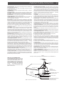
14. Outdoor Antenna Grounding—If an outside antenna or cable system is
connected to the product, be sure the antenna or cable system is grounded
so as to provide some protection against voltage surges and built-up static
charges. Article 810 of the National Electrical Code, ANSI/NFPA 70, provides
information with regard to proper grounding of the mast and supporting structure,
grounding of the lead-in wire to an antenna discharge unit, size of grounding
conductors, location of antenna-discharge unit, connection to grounding
electrodes, and requirements for the grounding electrode.
See Figure A.
15. Lightning—For added protection for this product during a lightning storm,
or when it is left unattended and unused for long periods of time, unplug it from
the wall outlet and disconnect the antenna or cable system. This will prevent
damage to the product due to lightning and power-line surges.
16. Power Lines—An outside antenna system should not be located in the
vicinity of overhead power lines, other electric light or power circuits, where it
can fall into such power lines or circuits. When installing an outside antenna
system, extreme care should be taken to keep from touching such power lines
or circuits as contact with them may be fatal.
17. Overloading—Do not overload wall outlets, extension cords, or integral
convenience receptacles as this can result in a risk of fire or electric shock.
18. Object and Liquid Entry—Never push objects of any kind into this product
through openings as they may touch dangerous voltage points or short-out parts
that could result in a fire or electric shock. Never spill liquid of any kind on the
product.
19. Servicing—Do not attempt to service this product yourself as opening or
removing covers may expose you to dangerous voltage or other hazards. Refer
all servicing to qualified service personnel.
20. Damage Requiring Service—Unplug this product from the wall outlet and
refer servicing to qualified service personnel under the following conditions:
a. When the power-supply cord or plug is damaged,
b. If liquid has been spilled, or objects have fallen into the product,
c. If the product has been exposed to rain or water,
d. If the product does not operate normally by following the operating
instructions. Adjust only those controls that are covered by the operating
instructions as an improper adjustment of other controls may result in damage
and will often require extensive work by a qualified technician to restore the
product to its normal operation,
e. If the product has been dropped or damaged in any way, and
f. When the product exhibits a distinct change in performance—this indicates
a need for service.
21. Replacement Parts—When replacement parts are required, be sure the
service technician has used replacement parts specified by the manufacturer
or have the same characteristics as the original part. Unauthorized substitutes
may result in fire, electric shock or other hazards.
22. Safety Check—Upon completion of any service or repairs to this product,
ask the service technician to perform safety checks to determine that the
product is in proper operating condition.
23. Wall or Ceiling Mounting—The product should be mounted to a wall or ceiling
only as recommended by the manufacturer.
24. Heat—The product should be situated away from heat sources such as
radiators, heat registers, stoves, or other products (including amplifiers) that
produce heat.
NOTE TO CATV SYSTEM INSTALLERS:
THIS REMINDER IS PROVIDED TO CALL THE
CATV SYSTEM INSTALLER'S ATTENTION TO
ARTICLE 820 - 40 OF THE NEC THAT PRO-
VIDES GUIDELINES FOR PROPER GROUND-
ING AND, IN PARTICULAR, SPECIFIES THAT
THE CABLE GROUND SHALL BE CONNECTED
TO THE GROUNDING SYSTEM OF THE
BUILDING, AS CLOSE TO THE POINT OF CABLE
ENTRY AS PRACTICAL.
POWER SERVICE GROUNDING
ELECTRODE SYSTEM
(NEC ART 250, PART H)
GROUND CLAMPS
GROUNDING CONDUCTORS
(NEC SECTION 810-21)
ANTENNA
DISCHARGE UNIT
(NEC SECTION 810-20)
ANTENNA
LEAD IN
WIRE
ELECTRIC
SERVICE
EQUIPMENT
GROUND CLAMP
NEC - NATIONAL ELECTRIC CODE
Figure A
Example of antenna grounding as per National Electrical Code, ANSI/NFPA 70

iv
This page left intentionally blank

Table of Contents v
Thank you for purchasing a DRAKE® FMC 1000 FM
STEREO MODULATOR. This product has been
designed and manufactured to high quality standards,
and will provide reliable operation for many years.
Please carefully read the Instruction Manual for proper
installation and usage.
Caution Statements
Important Safety Instructions
Table of Contents
Specifications / Options and Accessories
Introduction - General Description
Front Panel Controls and Indicators
Rear Panel Controls and Connections
Installation
Setup and Operation
Service Information / If You Need To Call For
Help
Warranty
ii
iii
v
vi
1
2
3
4
4
6
7

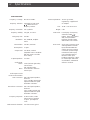
vi Specifications
SPECIFICATIONS -
Frequency Coverage:
Frequency Selection:
Frequency Generation:
Frequency Stability:
Tuning Step Size:
Modulation:
FM Deviation:
Pre-Emphasis:
Output Level:
Output Impedance:
Audio Inputs-
Stereo:
Mono:
Audio Input Level for
75 kHz Peak Deviation-
XLR Connectors:
RCA Phono Connectors:
Frequency Response:
Total Harmonic Distortion:
88.1 to 107.9 MHz.
Selectable by front panel
/ buttons and LCD
frequency readout.
PLL Synthesis.
±10 ppm, 0
0
to 50
0
C.
100 kHz.
FM, 200KF8E, multiplex
stereo.
±75 kHz, maximum.
75 µSec.
+50 dBmV, nominal
(adjustable +40 to +50 dBmV
with rear panel accessible
level control).
75 Ohms.
2 XLR (left and right audio),
2 RCA Phono
(left and right audio).
Use Left XLR or Left RCA
Phono input.
20K Ohm input impedance,
balanced.
-10 to +10 dBu manual gain
adjustment with front panel
modulation indicators.
20K Ohm input impedance,
balanced.
-16 to +4 dBu manual gain
adjustment with front panel
modulation indicators.
20 Hz to 15 kHz, ±3 dB
referenced to a standard
75 µSec. pre-emphasis
curve.
Less than 0.25%, typical.
12 VDC @ 250 mA,
regulated by supplied wall
AC Adapter.
19" W x 1.75" H x 6.25" D.
5 lbs.
LCD Display of Frequency
and Mode, TUNE /
buttons, Input Level Control
with (Over) Modulation
Indicators, Monitor output
with Monitor Level Control.
Qty (2) XLR connectors (Left
and Right Balanced Audio
Input) with GROUND LIFT
Switch, Qty (2) RCA Phono
Connectors (Left and Right
Unbalanced Audio Input),
Use Left Audio Inputs for
Monaural audio input,
Limiting/Compression switch,
DC Power Input with Power
On/Off Switch, and External
Antenna connector.
Power Requirement:
Size:
Weight:
Front Panel:
Rear Panel:

Introduction - General Description 1
The R.L. Drake FMC 1000 FM STEREO MODULATOR is
a high quality cable FM broadcast band modulator.
Synthesized operation permits setting the operating
frequency in 100 kHz increments from 88.1 to
107.9 MHz. The operating frequency and mode of
operation, Stereo or Mono, is programmable with front
panel buttons and is indicated on an LCD display. The
modulator accepts balanced or unbalanced line level
audio signals. Rear panel XLR connectors are provided
for left and right balanced audio inputs and RCA phono
connectors are provided for left and right unbalanced
audio inputs. A Ground Lift switch is also provided for
the XLR connectors. Full transmitter deviation with
monaural audio input is provided by programming the
unit for ‘MONO’ and connecting the audio signal input to
the appropriate Left Audio Input connector. A rear
panel Limiting/Compression switch permits setting no
limiting, limiting only, or limiting and compression
operation. A front panel Input Level control permits
adjusting the audio input level with LED (OVER)
MODULATION indicators. A front panel Monitor Output
connector is provided with separate monitor level
control. The unit is powered by a supplied external AC
line to 12 VDC power adapter. A rear panel Power
switch is also provided. The modulator can be rack
mounted in a standard 1 RU rack package.
TUNE
FMC 1000 FM STEREO MODULATOR
FREQUENCY
OVER MODULATION
LEFT
RIGHT
LEVEL
INPUT
MONITOR
MONITOR OUTPUT
107.9 MHz Stereo

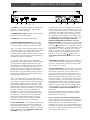
2 Front Panel Controls and Indicators
1. MONITOR OUTPUT - Connect headphones to listen
to the audio that is supplied to the transmitter. The
monitored level will vary with the level of the incoming
audio, the setting of the INPUT LEVEL control, and the
setting of the MONITOR OUTPUT level control.
2. MONITOR OUTPUT LEVEL Control - With the INPUT
LEVEL control set properly, adjust this control for a
comfortable listening level in the connected monitor
headphones.
3. INPUT LEVEL Control - This control is used to adjust
the input sensitivity. For a monaural audio input signal,
set this control at or just below the point where the
(OVER) MODULATION LED indicators light on audio
peaks. For a stereo input signal, set this control at or
just below the point where either of the (OVER)
MODULATION LED indicators light on audio peaks.
4. (OVER) MODULATION Indicators - These indicators
light to aid in the setting of the INPUT LEVEL control for
proper modulation. They light to indicate that full
modulation is being reached when the rear panel
LIMITING/COMPRESSION switch (see rear panel Item
4) is set to “OFF”. With the switch set for either the “L”
or “C+L” position, these indicators will light on audio
signal peaks as the limiter is activated at full modula-
tion. Also see rear panel Item 4 for additional hints for
proper setting of the LIMITING/COMPRESSION switch
for a given type of audio source. Set the INPUT LEVEL
control at or just below the point where the (OVER)
MODULATION indicators light on audio peaks.
5. TUNE / Buttons - Press to set the displayed
operating frequency: 88.1 - 107.9 MHz, in 100 kHz
increments. Press and hold both buttons until the
displayed ‘Mono’ or ‘Stereo’ flashes. Release both
buttons and press either or to alternately set
‘Stereo’ or ‘Mono’ as required. After a short delay, the
displayed 'Stereo' or 'Mono' will stop flashing. With a
steady 'Stereo' or 'Mono' displayed, the TUNE /
buttons permit setting the frequency.
6. FREQUENCY/Mode Display - Indicates the operat-
ing frequency and mode, Mono or Stereo, when the
rear panel ‘POWER’ switch is set to the ‘ON’ position
and the AC Adapter is connected and powered from an
AC source.
1 2 3 4 5 6
TUNE
FMC 1000 FM STEREO MODULATOR
FREQUENCY
OVER MODULATION
LEFT
RIGHT
LEVEL
INPUT
MONITOR
MONITOR OUTPUT
107.9 MHz Stereo

20K
20K
20K
20K
UNBALANCED
16 TO 4dBu
+
-
-
BALANCED
BALANCED
UNBALANCED
-
-
1 GND
-
-
2 HIGH
-
-
3 LOW
10 TO 10dBu
+
-
-
16 TO 4dBu
+
-
-
10 TO 10dBu
+
-
-
G R O U N D
L I F T
MADE IN U.S.A.
BY
R
D C I N P U T
ON OFF
12 VDC 250 mA
+
-
-
P O W E R
OFF C + L
L
L E F T A U D I O
I N P U T
ON OFF
R I G H T A U D I O
I N P U T
(MONO)
R F O U T P U T
L I M I T I N G /
C O M P R E S S I O N
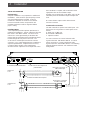
Rear Panel Controls and Connections 3
1. DC INPUT - Connect the supplied AC Adapter to this
connector. Secure AC Adapter DC cable with the
adjacent rear panel strain relief.
2. POWER ON/OFF Switch - Set this switch to the ‘ON’
position to operate the FMC 1000.
3. RF OUTPUT - This is the modulator output.
4. LIMITING/COMPRESSION SWITCH - This switch
selects the operation of the limiter. Select the proper,
or desired, setting according to the following criteria:
“OFF” - For audio sources with limiting and/or compres-
sion already applied. This setting bypasses the limiting
circuitry of the FMC 1000. With the audio source
connected, adjust the INPUT LEVEL control to a setting
at or just below the point where the (OVER) MODULA-
TION indicators light on audio peaks.
“L” - For most types of audio sources and listening
environments. This setting provides automatic limiting
on audio peaks to prevent loud bursts and to avoid
over modulation conditions which can cause distorted
audio at the receiver. With the audio source con-
nected, (for example, the output of a public address
amplifier with a person speaking at a normal level into
the microphone), adjust the INPUT LEVEL control to a
setting at the point where the (OVER) MODULATION
indicators light on audio peaks.
“C+L” - For audio sources that contain relatively low
audio levels combined with relatively high audio levels
as might be encountered when the audio output from a
public address amplifier contains audio from multiple
microphones with different persons speaking. This
setting provides automatic increasing of the low level
audio passages combined with limiting on voice peaks.
This type of audio processing can sometimes aid
intelligibility for a person receiving the signal while
located in a relatively noisy audio environment. With
the audio source connected, and the weaker audio
levels active, adjust the INPUT LEVEL control to a
setting at or just below the point where the (OVER)
MODULATION indicators light on audio peaks.
5. LEFT AUDIO INPUT - Connect monaural audio input
signals to the appropriate unbalanced or balanced
LEFT AUDIO INPUT connector. For monaural input,
program the FMC 1000 to display ‘MONO’. See Item 5;
'TUNE / Buttons' in the ‘Front Panel Controls and
Indicators' section of this manual.
For stereo input, connect an unbalanced line level left
channel stereo audio signal to the phono connector or
connect a balanced line level left channel stereo audio
signal to the 3-pin female XLR connector. The unbal-
anced phono style input and the XLR balanced input
on a given input (Left or Right) are each always active,
so audio will be fed from whichever input is being used.
Do not attempt to connect signals to both the
unbalanced and balanced connectors on a given
input (Left or Right). All inputs can be considered high
impedance (>20K Ohm). The shield connection at pin
1 of the XLR connector can be conveniently connected
to ground (GROUND LIFT = ‘OFF’) or lifted from ground
(GROUND LIFT = ‘ON’) to eliminate hum or noise as
required. For stereo input, program the FMC 1000 to
display ‘STEREO’. See ‘Front Panel Controls and
Indicators: See Item 5; 'TUNE / Buttons' in the
‘Front Panel Controls and Indicators' section of this
manual.
6. GROUND LIFT Switch - Set to the ‘OFF’ position to
connect pin 1 of both LEFT and RIGHT XLR connectors
to ground. Set to the ‘ON’ position to disconnect both
XLR connectors from ground.
7. RIGHT AUDIO INPUT - For stereo input, connect an
unbalanced line level right channel stereo audio signal
to the phono connector or connect a balanced line
level right channel stereo audio signal to the 3-pin
female XLR connector. Never connect signals to both
the unbalanced and balanced connectors on a given
input (Left or Right). The shield connection at pin 1 of
the XLR connector can be conveniently connected to
ground (GROUND LIFT = ‘OFF’) or lifted from ground
(GROUND LIFT = ‘ON’) to eliminate hum or noise as
required. For stereo input, program the FMC 1000 to
display ‘STEREO’. See Item 5; 'TUNE / Buttons' in
the ‘Front Panel Controls and Indicators' section of
this manual.
Connect a monaural audio signal to the appropriate
LEFT AUDIO INPUT connector. See Item 5: 'LEFT
AUDIO INPUT', on this page.
8. Access Hole for RF OUTPUT Level Adjustment -
The RF output level can be reduced to a value approxi-
mately 10 dB below the nominal level by adjustment of
the potentiometer. The potentiometer is tunable
through the access hole. Use a small straight-slot type
screwdriver to adjust the potentiometer, if adjustment is
necessary. Counterclockwise rotation of the potentiom-
eter decreases the output level.
1 2 3 8 4 5 6 7

20K
20K
20K
20K
UNBALANCED
16 TO 4dBu
+
-
-
BALANCED
BALANCED
UNBALANCED
-
-
1 GND
-
-
2 HIGH
-
-
3 LOW
10 TO 10dBu
+
-
-
16 TO 4dBu
+
-
-
10 TO 10dBu
+
-
-
G R O U N D
L I F T
MADE IN U.S.A.
BY
R
D C I N P U T
ON OFF
12 VDC 250 mA
+
-
-
P O W E R
OFF C + L
L
L E F T A U D I O
I N P U T
ON OFF
R I G H T A U D I O
I N P U T
(MONO)
R F O U T P U T
L I M I T I N G /
C O M P R E S S I O N
4 Installation
SETUP and OPERATION
Rack Mounting
Adequate ventilation is very important in multichannel
installations. Units should be spaced apart by at least
one panel height wherever possible. Some air
movement is advisable in enclosed rack cabinets.
Excessive heat will shorten component life and
modulator performance will be degraded without
proper cooling.
Installation Notes
Level adjustment provides optimum performance in
multichannel installations. The RF output level from the
FMC 1000 is +50 dBmV nominal. The level can be
reduced to a value approximately 10 dB below the
nominal level by adjustment of the potentiometer that is
tunable through the rear panel access hole. The
access hole is located adjacent to the RF OUTPUT
connector. Use a small straight-slot type screwdriver to
adjust the potentiometer, if adjustment is necessary.
Counterclockwise rotation of the potentiometer
decreases the RF output level. If an output level of less
than +40 dBmV is required, add an attenuator of the
appropriate value to the modulator output.
Example:
For an output level of +35 dBmV, add a 10 dB
attenuator pad to the modulator output and adjust the
level.
1. Connect the RF Output coaxial cable to the RF
OUTPUT connector.
2. Make audio connections
The FMC 1000 will accept line level audio inputs. The
best sources for a signal from a sound system are as
follows:
A. TAPE OUT or LINE OUT
B. BOOSTER or BRIDGING
C. Speaker Terminal
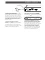
Use XLR connectors to connect balanced audio
signals to the FMC 1000 AUDIO INPUTs. Use RCA
phono connectors to connect unbalanced audio
signals to the FMC 1000 AUDIO INPUTs. The following
diagrams illustrate balanced and unbalanced audio
wiring details:
Balanced
Line
Unbalanced
Line
Male XLR Connector To
FMC 1000 Input
RCA Phono Connector
To FMC 1000 Input
Shield Grounded As Required
12
3
OR
To Combiner/Cable Distribution Access hole for RF output level
potentiometer
-
+

MADE IN U.S.A.
BY
R
D C I N P U T
ON OFF
12 VDC 250 mA
+
-
-
P O W E R
OFF C + L
L
R F O U T P U T
L I M I T I N G /
C O M P R E S S I O N
Installation, continued 5
To set the mode, press and hold both TUNE /
buttons until the mode ‘MONO’ or ‘STEREO’ flashes.
Press either TUNE / button to set the required mode.
TUNE
FMC 1000 FM STEREO MODULATOR
FREQUENCY
OVER MODULATION
LEFT
RIGHT
LEVEL
INPUT
MONITOR
MONITOR OUTPUT
107.9 MHz Stereo
5. Set the INPUT and MONITOR Level Controls
With the audio source active, and the desired type of
limiting set, adjust the INPUT LEVEL control clockwise
until the (OVER) MODULATION LED indicators just
begin to light on audio signal peaks. Refer to the “Rear
Panel Controls and Connections” (Item 4) and the
“Front Panel Controls and Indicators” (Items 3,4)
sections of this manual for details. To monitor the
audio source material, plug a set of headphones into
the MONITOR OUTPUT jack. Adjust the MONITOR
Level control for a comfortable listening level.
3. Connect the Transmitter to Power
Plug the DC power cord of the supplied AC Adapter
into the DC INPUT connector on the rear panel of the
FMC 1000 unit. Secure the DC power cord with the
adjacently located strain relief. Plug the AC Adapter
into a nominal 120 VAC, 60 Hz wall outlet. Set the rear
panel POWER switch to the ‘ON’ position. The front
panel display should now indicate the operating
frequency and mode.
4. Set the Operating Frequency and Mode
Press the front panel
/ button to set the operating
frequency.
If a monaural audio source is being supplied to the
FMC 1000, set the displayed mode to ‘MONO’. Set for
‘STEREO’ with stereo audio source material.
Switch to 'ON'
Strain Relief

6 Service Information / If You Need To Call For Help
SERVICE INFORMATION
You may contact the R.L. DRAKE Service Department for
additional information or assistance by calling
+1 (937) 746-6990, Monday through Friday, between
8:00 A.M. and 4:00 P.M. Eastern Time, except on holidays.
You may also contact the R.L. DRAKE Service Department by
E-mail at the following address:
or by Telefax:
+1 (937) 743-4576.
Should you want to return your unit for service, package
the unit carefully using the original carton or other
suitable container.
Write your return address clearly on the shipping carton
and on an enclosed cover letter describing the service
required, symptoms or problems. Also include your
daytime telephone number and a copy of your proof of
purchase.
The unit will be serviced under the terms of the
R.L. DRAKE COMPANY Limited Warranty and returned
to you.
Red is an overnight service. Send the unit in a way that it
can be traced if we can’t verify receipt of shipment. We
suggest UPS or insured postal shipment.
If the unit is still under the original owner’s warranty,
R.L. DRAKE will pay the cost of the return shipment to
you. Our return shipping policy is that we will return it
UPS Brown if received Brown or by US Mail, it will be
returned Blue if received Blue or Red—or it will be
returned however you prefer if you furnish the return cost
for the method you select.
If the unit is out of warranty, it will be returned by UPS
Brown label COD (UPS does not accept cash/currency)
unless:
1) It was received UPS Blue/Red, in which case it will be
returned UPS Blue/Red COD;
2) You designate billing to American ExPress, VISA,
MasterCard or Discover card;
3) You prepay the service charges with a personal check,
or
4) You specify some other method of return.
When calling, the technician can estimate the repair
charges for you over the phone. This is another good
reason to call before sending a unit in for repair.
Typically, equipment is repaired in five to ten working
days after it arrives at R.L. DRAKE if we have all the facts.
If we must call you, it may take longer. R.L. DRAKE is not
responsible for damage caused by lightning, nonprofes-
sional alterations, “acts of God”, shipping damage, poor
storage/handling, etc. R.L. DRAKE will make note of any
shipping damage upon receipt.
Should your warranty card not be on file at R.L. DRAKE,
you will need to send proof of purchase to receive
warranty service. Typically, a copy of the invoice from an
R.L. DRAKE dealer will suffice. The warranty is for the
original owner only and is not transferable.
IF YOU NEED TO CALL FOR HELP
Call our Customer Service/Technical Support line at
+1 (937) 746-6990 between 8:00 A.M. and 4:00 P.M.
Eastern Time, weekdays. Please have the unit’s serial
number available. We will also need to know the specifics
of any other equipment connected to the unit.
When calling, please have the unit up and running, near
the phone if possible. Our technician(s) will likely ask
certain questions to aid in diagnosis of the problem. Also,
have a voltmeter handy, if possible.
R.L. DRAKE also provides technical assistance by
e-mail: [email protected]
or by Telefax: +1 (937) 743-4576.
Many of the products that are sent to us for repair are in
perfect working order when we receive them. For these
units, there is a standard checkout fee that you will be
charged. Please perform whatever steps are applicable
from the installation sections of the Owner's Manual
before calling or writing—this could save unnecessary
phone charges. Please do not return the unit without
contacting R.L. DRAKE first: it is preferred to help
troubleshoot the problem over the phone (or by mail) first,
saving you both time and money.
Inside the carton, enclose a note with your name,
address, daytime phone number, and a description of the
unit’s problem.
The unit must be sent to the following address:
Service Department
R.L. DRAKE COMPANY
230 Industrial Drive
Franklin, Ohio 45005 U.S.A.
Be sure to include your street address which will be
needed for UPS return. UPS Surface (Brown Label) takes
7-10 days to reach us depending on your location, Blue
takes 2-3 days.

Warranty 7
Three Year Limited Warranty
R.L. DRAKE COMPANY warrants to the original purchaser this product shall be free from defects in material or
workmanship for three (3) years from the date of original purchase.
During the warranty period the R.L. DRAKE COMPANY or an authorized Drake service facility will provide, free of
charge, both parts and labor necessary to correct defects in material and workmanship. At its option,
R.L. DRAKE COMPANY may replace a defective unit.
To obtain such a warranty service, the original purchaser must:
(1) Retain invoice or original proof of purchase to establish the start of the warranty period.
(2) Notify the R.L. DRAKE COMPANY or the nearest authorized service facility, as soon as possible after discovery
of a possible defect, of:
(a) the model and serial number,
(b) the identity of the seller and the approximate date of purchase; and
(c) A detailed description of the problem, including details on the electrical connection to associated equipment and
the list of such equipment.
(3) Deliver the product to the R.L. DRAKE COMPANY or the nearest authorized service facility, or ship the same
in its original container or equivalent, fully insured and shipping charges prepaid.
Correct maintenance, repair, and use are important to obtain proper performance from this product. Therefore
carefully read the Instruction Manual. This warranty does not apply to any defect that R.L. DRAKE COMPANY
determines is due to:
(1) Improper maintenance or repair, including the installation of parts or accessories that do not conform to the quality
and specifications of the original parts.
(2) Misuse, abuse, neglect or improper installation.
(3) Accidental or intentional damage.
All implied warranties, if any, including warranties of merchantability and fitness for a particular purpose, terminate
three (3) years from the date of the original purchase.
The foregoing constitutes R.L. DRAKE COMPANY’S entire obligation with respect to this product, and the original
purchaser shall have no other remedy and no claim for incidental or consequential damages, losses or expenses.
Some states do not allow limitations on how long an implied warranty lasts or do not allow the exclusions or
limitation of incidental or consequential damages, so the above limitation and exclusion may not apply to you.
This warranty gives you specific legal rights and you may also have other rights which vary from state to state.
This warranty shall be construed under the laws of Ohio.
For Service, contact:
R.L. DRAKE COMPANY
230 Industrial Drive
Franklin, Ohio 45005 U.S.A.
Customer Service and Parts Telephone: +1 (937) 746-6990
Telefax: +1 (937) 743-4576
World Wide Web Site: http://www.rldrake.com

R.L. DRAKE COMPANY
230 INDUSTRIAL DRIVE
FRANKLIN, OHIO 45005 U.S.A.
CUSTOMER SERVICE AND PARTS TELEPHONE: +1 (937) 746-6990
TELEFAX: +1 (937) 743-4576
WORLD WIDE WEB SITE: http://www.rldrake.com
-
 1
1
-
 2
2
-
 3
3
-
 4
4
-
 5
5
-
 6
6
-
 7
7
-
 8
8
-
 9
9
-
 10
10
-
 11
11
-
 12
12
-
 13
13
-
 14
14


Ask a question and I''ll find the answer in the document
Finding information in a document is now easier with AI
Related papers
Other documents
-
AG Neovo FMC-02 User manual
-
 T'nB CAJJ Datasheet
-
 T'nB CAJJ02 Datasheet
-
Listen Technologies lt-800 User manual
-
-
Power Acoustik EFM-01 User manual
-
-
Listen Technologies LR-100 Series User manual
-
-

