Page is loading ...

*2P1109* *P506052-01*
2009 Lennox Industries Inc.
Dallas, Texas, USA
INSTALLER’S SYSTEM SETUP
GUIDE
icomfortt Thermostat
Touch Screen Programmable Communicating Thermostat
CONTROLS
506052−01
11/09
Shipping and Packing List1
1 − icomfort Touch Screen Communicating, 7−day Programmable
Thermostat
6 − Mounting Screws
6 − Wall Anchors
1 each − Installation Quick-Start Guide, Installer’s System Setup Guide,
Homeowner’s Manual, Warranty card, Warranty Audit tag
Litho U.S.A.

506052−01 11/09
Page 2
Table of Contents
icomfort Thermostat Terms and Acronyms 3. . . . . . . . . . . . . . . . .
icomfort Technical Description 4. . . . . . . . . . . . . . . . . . . . . . . . . . .
icomfort Thermostat Features 5. . . . . . . . . . . . . . . . . . . . . . . . . . .
Installing icomfort Thermostat 5. . . . . . . . . . . . . . . . . . . . . . . . . . .
Installer setup 6. . . . . . . . . . . . . . . . . . . . . . . . . . . . . . . . . . . . . . . . . .
System settings 7. . . . . . . . . . . . . . . . . . . . . . . . . . . . . . . . . . . . .
Setting time and date 8. . . . . . . . . . . . . . . . . . . . . . . . . . . . . . . . .
Add/remove/modify non−communicating devices 9. . . . . . . . .
Modify communicating device settings 10. . . . . . . . . . . . . . . . . .
Indoor air quality controls 12. . . . . . . . . . . . . . . . . . . . . . . . . . . . .
Tests 14. . . . . . . . . . . . . . . . . . . . . . . . . . . . . . . . . . . . . . . . . . . . . . . . . .
Diagnostics 17. . . . . . . . . . . . . . . . . . . . . . . . . . . . . . . . . . . . . . . . . . . .
Alerts 18. . . . . . . . . . . . . . . . . . . . . . . . . . . . . . . . . . . . . . . . . . . . . . . . .
Access installer program from User Home screen 22. . . . . . . . . . . .
Reconfiguring a system 23. . . . . . . . . . . . . . . . . . . . . . . . . . . . . . . . . .
Editable parameters table (user and Installer) 25. . . . . . . . . . . . . . . .
Alarm Codes and Descriptions 31. . . . . . . . . . . . . . . . . . . . . . . . . . . .
Wiring Diagrams 36. . . . . . . . . . . . . . . . . . . . . . . . . . . . . . . . . . . . . . . .
WARNING
Always turn off power at the main power source by switching the
circuit breaker to the OFF position before installing or removing
this thermostat.
All wiring must conform to local and national building and electri-
cal codes and ordinances.
Do not switch system to cool if the outdoor temperature is below
45°F (7°C). This can damage the cooling system.
CAUTION
This is a 24VAC low−voltage thermostat. Do not install on volt-
ages higher than 30VAC.
Do not short (jumper) across terminals on the gas valve or at the
system control to test installation. This will damage the thermo-
stat and void the warranty.
IMPORTANT
Read this manual before programming this thermostat.
Use this thermostat only as described in this manual.

icomfort Touch Screen 7−Day Programmable Thermostat
Page 3
icomfortt Thermostat Terms and Acronyms
Subnet Controller (SC): (part of the communicating thermostat) Local
device that controls the system.
Subnet: A part of the communication network that contains devices to
control one functional HVAC system.
RSBus − Residential Serial Bus − the means for transmitting data within
the communicating system.
Controller Area Network Protocol: Rules for networking, for transmis-
sion and receipt of information between communicating systems.
Baud Rate: Maximum speed of BUS 40K baud.
Byte: 8 bits of information transmitted on the RSBus.
Integrated Furnace Control (IFC): Communicating control for furnace.
IFC controls ignition, CAI, blower, and monitors all safety features in the
unit.
Air Handler Control (AHC): Communicating control for air handler
units. AHC controls operation of blower, heat strips, and monitors all
safety features in the unit.
HP Control (Defrost Control) (UC): Communicating defrost control.
UC controls low and high speed compressor operation, defrost opera-
tions, fan motor, and reversing valve and monitors all safety features in
the unit.
AC Control: Communicating air conditioning control. AC controls low
and high speed compressor operation, fan motor operation, and all safe-
ty monitors in the unit.
Discharge Air Sensor (DAS): Communicating discharge air sensor.
Provides discharge air temperature to Bus, UI, and IFC for proper opera-
tion of equipment.
R: 24V power
C: 24V common
i+: + data information connection
i−: − data information connection
Configuration: Function that accrues during setup of system to identify
other communicating devices. Configuration is also used in setup of a
variable capacity furnace to properly set furnace parameters.
Memory Fault Recall: Method of checking for errors
Firmware: Software stored on a memory chip instead of being part of a
program
Software: Programming and applications for computer

506052−01 11/09
Page 4
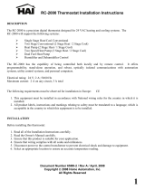
icomfortt Technical Description
The 24VAC icomfort thermostat stores system parameters and set-
tings in a nonvolatile memory (i.e., it retains data when electrical power
fails or is turned off). The thermostat (see figure 1) also:
includes on-board help screens,
supports heat pumps or non−heat pump units, with up to 4 stage
heat / 2 stage compressor operation. (2 stages of heat pump heat-
ing and 2 stages of auxiliary backup heat are provided. Also, 2
stages of emergency heat are provided),
supports Indoor Air Quality with time-based notification of consum-
ables including media filters, UVC bulbs, humidifier pads, and
PureAir catalyst service / replacement,
supports variable capacity / multistage heat/cool, universal com-
patibility (gas/electric/heat pump/ac), and is dual fuel capable with
two balance points.
Important
Always use correct software version as recommended for replacement
configuration (discovery).
Connections to non communication outdoor units and all accessories is
described in the Quick−Start Installation guide. (Wiring diagrams are also
shown beginning on Page 36.)
Thermostat
connections
RSBUS
Minimum wire size is
18 gauge
icomfort Outdoor Units Control
icomfort Furnace Control
icomfort Air Handler Control
External Sensors − outdoor temperature and humidity
Humidify control
Dehumidify control
R I+ I − C
Maximum total length
of all connections on
the RSBus is limited
to 1500ft.
Figure 1. icomfort thermostat system

icomfort Touch Screen 7−Day Programmable Thermostat
Page 5
icomfortt Thermostat Features
Thermostat Type
Electronic communicating, color display touch screen, 7−day program-
mable.
Supports
Humidification Measurement and Control,
Dew Point Adjustment Control,
Dehumidification Measurement and Control,
Humiditrol
®
Enhanced Dehumidification Accessory (EDA),
Multi-stage HVAC Systems,
Equipment Maintenance Reminders.
On-board Help Screens.
The icomfort thermostat’s autochangeover mode permits control of
heating, cooling, humidification, and dehumidification without user in-
volvement.
Outdoor Temperature Sensor
Communicating outdoor units contain a built in outdoor temperature sen-
sor.
Installing icomfortt thermostat
Refer to the Quick Start Guide for all the information about installing the
thermostat to a wall and for wiring diagrams for connecting the thermo-
stat to the system using one of a number of possible configurations.
(Wiring diagrams are also shown beginning on Page 36.)
After all the wiring is in place, apply power to the system. 24VAC will be-
gin to power up the thermostat.
Continue with the Installer setup that follows.

506052−01 11/09
Page 6
Installer setup − Page 1 of 8
After power is applied to the thermostat for the first time, the processor
checks the system for installed communicating devices, the System
discovery" screen (figure 2) is displayed on the thermostat; followed by
the Use this thermostat" screen (figure 3). Press press here to contin-
ue.
SYSTEM DISCOVERY IN PROGRESS
Figure 2. System discovery
tests
Thermostat 1
Use this Thermostat?
press here
setup HELP
Figure 3. Use this thermostat screen
During the setup process, alerts may pop open to inform the installer
some item of information that affects the setup (figure 4). Tend to any
such alerts prior to continuing setup.
Active
Critical Alert Code: 31
AIR HANDLER reports:
Lost Communication with
THERMOSTAT −
Latest occurrence: 8/23/09
1:57 PM
press for more
critical alert
close
Figure 4. Alert window

icomfort Touch Screen 7−Day Programmable Thermostat
Page 7
Installer setup − Page 2 of 8
System settings (figure 5) appear first. As you use the up/down arrows
to scroll through the settings, the right hand side will show the current
value, for example, Current Value: (35% ) shows the current setting of
the Circulate Fan ON time.
edit
next step
back
setup HELP
Time and Date
Daylight Saving
Time
Circulate Fan ON
time
Dealer Name
Dealer Address
Dealer Phone
Number
Dealer Email
To view/edit a setting,
highlight it, then press edit.
Current Value:
(35%)
system settings
Figure 5. System settings
The following shows the range/condition and defaults for the settings.
system setting range/condition default use
Time and Date see Page 8
Daylight Saving Time Enabled/Disabled Enabled
Circulate Fan ON Time 15 to 45 35%
Dealer Name
(alpha−numeric
characters)
Lennox
1−800−9−LENNOX
www.lennox.com
use type
writer to
change
Dealer Address
Dealer Phone Number
Dealer Email
Dealer Website
If you want to modify a setting, use one of the tools shown in figure 6.
(Make time and date as described on Page 8.) After changes have
been made, use save to store the changed data or cancel to exit the
screen and return to the list of settings.
up/down arrows
scroll through a
numeric range for
some settings
save
cancel
Daylight Saving Time
Enabled
Disabled
typewriter tool to input
names, address, phone
numbers etc.
*
=
r
Lennox Repairman
Dealer Name
21
qwe
43658709
ityu po
f
@!
asd
$#^%(&)
kghj l
v
−
zxc
_
/
+
.
bnm
space
back
space
symbols
CAPS
ON
save
cancel
Figure 6. Settings change tools

506052−01 11/09
Page 8
Installer setup − Page 3 of 8
Setting time and date
Use the arrows to select Time and Date; press edit (see figure 7). Press
next to proceed to the Set current time and date" screen (figure 8).
tests
setup HELP
system settings
to adjust a setting, highlight
it, then press edit.
Current Value:
(September 15, 2009,
09:23 AM)
edit
next step
back
Time and Date
Daylight Saving
Time
Circulate Fan ON
time
Dealer Name
Dealer Address
Dealer Phone
Number
Dealer Email
Figure 7. View/edit time and date
When the Time and Date" screen appears, enter the correct date as fol-
lows:
Press one of the time and date boxes − the text will change to white
type in a dark box (for example, press the 10" box in figure 8).
Press the up/down arrows to change the data.
Press other boxes and adjust with the arrows for all time and date
information. When the date and time is correct, press save to save
settings and return to previous settings screen.
adjust
Time and Date
10 :19 AM
Oct 15 2009
save
cancel
setup HELP
Figure 8. Set current time and date
NOTE − After setting the time and date, if you don’t need to add any non−
communicating devices, you may wish to accept the default system pa-
rameters and skip forward to tests". To do so, repeatedly press next
step on each screen until you get to the tests screen. From there, you
can check the systems operation. Thereafter, should you need to
change a communicating device parameter, access those settings by
pressing the equipment tab in the installer section.

icomfort Touch Screen 7−Day Programmable Thermostat
Page 9
Installer setup − Page 4 of 8
Add/remove/modify non−communicating devices
From this screen (figure 9), use the yes button to access a list of non−
communicating devices for installing or removing. A list similar to that
shown in figure 10 will appear.
setup HELP
yes
next stepback
Add or Remove
Non−communicating
equipment?
HP
XP19−060−230−06
5809K00015
AIR HANDLER
CBX32MV−60
5809K00020
THERMOSTAT
49W95
A109K00139
SYSTEM
system devices
Figure 9. Add/remove/modify non−communicating devices
Humidification / Dehumidification Control Modes depend on a hu-
midifier and/or dehumidifier being added to the system. Therefore, you
must press yes on the button near "Add or Remove Non−communicating
equipment?" Also, in order for the user’s display to show these controls,
the system controls must be set. See Page 12 for more information.
Use the up/down arrows (see figure 10) to select a setting. The right hand
side of the screen indicates what is currently selected, for example, Cur-
rent Value: (Not Installed); press edit if you want to modify that setting.
setup HELP
edit
back
non−communicating
device list
HUMIDIFIER
DEHUMIDIFIER
UV LIGHT
to adjust a setting, highlight it,
then press edit
Current Value:
(Not Installed)
Figure 10. Installing UV Light
A typical Installed status screen (Figure 11) shows if the device is not
installed or type of equipment installed. Use the arrows to change and
use save to save the change. (Cancel goes pack to previous screen.)
Installed Status
save
cancel
Not Installed
UV LIGHT
Figure 11. Typical non−communicating device edit screen

506052−01 11/09
Page 10
Installer setup − Page 5 of 8
Modify communicating device settings
Use this screen (figure 12) to access communicating devices’ settings.
Use back to return to the previous screen or next step to go on.
HP
XP19−060−230−06
5809K00015
AIR HANDLER
CBX32MV−60
5809K00020
THERMOSTAT
49W95
A109K00139
SYSTEM
setup HELP
about
next step
back
system devices
edit
reset ALL
to adjust a device, highlight
it, then press edit
Figure 12. Accessing communicating device settings
With one of the devices highlighted, press about, then use arrow keys to
see a list of data about the selected device. If you select reset ALL, and
then confirm, ALL devices will be reset to their factory settings. (You
would see a screen similar to figure 14.)
With one of the devices in figure 12 highlighted, press edit to go to that
device’s list of settings (see figure 13).
Use the up/down arrows to scroll through the device’s settings and ob-
serve the right hand side of the screen (figure 13) to see the current set-
ting, for example, Current Value: (Off). Press edit if you want to modify
that setting, or press back to return to the previous screen.
Equipment Name
Compressor Short
Cycle Delay
Defrost
Termination Temp
Compressor Shift
Delay On/Off
setup HELP
back
HP
edit
reset
to adjust a setting, highlight it,
then press edit
Current Value:
(Off)
Figure 13. Modify communicating device settings
Settings available for the devices are dependant on the components you
have. Shown below is an example of changing the compressor shift
delay on. After using the arrows to select On, press save to save the
changes and return to the previous screen.
save
cancel
On
Off
Compressor Shift Delay On/Off

icomfort Touch Screen 7−Day Programmable Thermostat
Page 11
Installer setup − Page 6 of 8
If you select reset and then confirm, the highlighted device will be reset
to its factory setting. You would see a screen similar to figure 14, but ref-
erencing only the selected device.
confirm
cancel
Resetting ALL devices to their factory default
settings will cause the system to restart the
setup process. If you want to continue, then
press ’confirm’ or press ’cancel’.
Figure 14. Reset device confirmation note
After a reset, the device which had its settings reset to
default will display in the system devices screen in red
type. You will be required to highlight the red−type de-
vice(s) and use edit (see figure 12) to change, or at
least view the changed settings of the red−type de-
vices .
HP
XP19−060−230−06
5809K00015
AIR HANDLER
CBX32MV−60
5809K00020
In the edit mode, the feature list will show the selected
device’s changed features in red type. Use the up/
down arrows to select each red−typed feature and
press edit. Make changes to the settings using the
Edit tools if desired, or at least, press save in each fea-
ture screen. Upon saving, the previous screen will
display and the type will again be black. Press back to
return the Modify communicating device settings
screen.
Equipment
Name
Electric Heating
Airflow
Low Cooling
Airflow
Low Cooling
Airflow
At this point press next step to advance to the test controls.

506052−01 11/09
Page 12
Installer setup − Page 7 of 8
Indoor air quality controls
An example of installing UV Light is shown in figure 10, Page 9.
To turn on humidification or dehumidification controls, in addition to
the setup described on Page 9, work from either the setup tab or the
equipment tab to get to the adjustment screen (figure 15). Use the arrows
to highlight the SYSTEM selection. Press edit.
A long list of features are listed on the right of the next screen (see figure
16). Use the arrows to locate Humidification Control Mode and/or De-
humidification Control Mode. Press edit.
Depending on the type of equipment installed, the lists of options may be
different than those shown in figure 17. In order for either or both of these
controls to display, the selected option must be other than Display
Only".
setup tests equipment HELP
XP19−060−230−06
5809K00015
AIR HANDLER
CBX32MV−60
5809K00020
THERMOSTAT
49W95
A109K00139
SYSTEM
49W95
A109K00139
about
next step
back
(to adjust a device, highlight
it, then press edit)
system devices
edit
reset ALL
Figure 15. Accessing the SYSTEM adjustment screen

icomfort Touch Screen 7−Day Programmable Thermostat
Page 13
Installer setup − Page 8 of 8
setup tests equipment HELP
Equipment Name
Filter 1 Timer
Selection
.
.
(various)
.
.
Dehumidification
Control Mode
Humidification
Control Mode
back
(to adjust a setting, highlight
it, then press edit)
Current Value:
(Display Only)
SYSTEM
edit
reset
Figure 16. SYSTEM adjustment screen
save
cancel
Display Only
Basic
Precision
Dew Point Control
save
cancel
Display Only
Basic
Precision
Humiditrol
(or Auxiliary
Dehumidifier)
Humidification Control Mode
Dehumidification Control Mode
Figure 17. Selecting Dehumidification/Humidification mode
HUMIDIFICATION modes
BASIC & PRECISIONthese modes allow user control of RH between
15 and 45%. These conditions must be met for either mode to operate:
humidification mode has been enabled, and
the unit is in HEAT mode, and
humidification demand exists (24V present at H), and
BASIC mode also requires heat demand exists (Y for HP heat, or W for
gas heat [W may be energized with G de−energized]).
DEW POINT CONTROLDew point adjustment mode will change the
humidification setpoint based on the outdoor temperature and a user−de-
fined dew point adjustment setting.
DEHUMIDIFICATION modes
In BASIC mode, dehumidification occurs if these conditions are met and
signals are present at specific terminals:
dehumidification has been enabled on installer settings, and
the unit is in COOL mode, and
dehumidification demand exists (RH above setpoint), and
cooling demand exists (Y1 energized).
In PRECISION mode, dehumidification occurs if all BASIC conditions
are true, except cooling demand may or may not be present. Maximum
overcool from cooling set point is 2ºF.
HUMIDITROL or AUX. DEHUMIDIFIER mode requires:
outdoor sensor must be installed and setup
dehumidification has been enabled on installer settings, and
the unit is in COOL mode, (or if in AUTO, at least one thermostat cooling
call made prior to the dehumidification demand), and
a dehumidification demand exists (RH above setpoint), and
outdoor temp. below 95°F; indoor temp. above 65°F, and
for HUMIDITROL, Humiditrol comfort adjust parameters as follows:
MAX adj. − Indoor temp > 2°F above heating setpoint
MID adj. − Indoor temp >
HEAT SETPOINT+COOL SETPOINT
2
MIN adj. − Indoor temp > 2°F below cooling setpoint

506052−01 11/09
Page 14
Tests − Page 1 of 1
The tests feature is not available until after setup has been completed
once. After you press next step in the final setup screen, the Select
tests to run" screen (figure 18) appears.
If you re−select the tests tab from any other screen, a message to press
Start button below to begin system testing" appears; press start.
setup tests equipment HELP
selected tests
select tests to run
select
TEST ALL
Blower
HP Heat − 1st
Stage
HP Heat − 2nd
Stage
Defrost Now
Cooling − 1st
Stage
Cooling − 2nd
Stage
skip tests
press start button below to begin system testing
start
alerts diagnostics EXIT
Figure 18. Select tests to run
When the tests screen opens, TEST ALL will be highlighted (but not yet
selected). If you want to run TEST ALL, press select. Note your selection
on the right side says selected test TEST ALL". Also, note there are now
two buttons along the bottom labeled remove and start. Use remove to
deselect a selected test.
If you prefer, run tests one−at−a−time using the arrows to highlight a de-
sired test and then press select.
Press start to begin testing.
setup tests equipment HELP
selected tests
TEST ALL
select tests to run
select
TEST ALL
Blower
HP Heat − 1st
Stage
HP Heat − 2nd
Stage
Defrost Now
Cooling − 1st
Stage
Cooling − 2nd
Stage
startremove
alerts diagnostics EXIT
Figure 19. Start running tests

icomfort Touch Screen 7−Day Programmable Thermostat
Page 15
Tests − Page 1 of 1
After the tests have been started, the screen will describe which test is
running (see figure 20). After concluding that the results are the desired
results for any test, press next (if using TEST ALL) to proceed to the next
test or done (if running a single test).
CURRENT TEST: Blower
Check Blower Operation
done
cancel
CURRENT TEST: Blower
Check Blower Operation
next
cancel
TEST ALL example
single test example
Figure 20. Typical tests results screens
After pressing done, the Testing finished" screen will appear (see figure
21). At this point, use the EXIT tab (if you are finished with all setup), or
use diagnostics tab (to analyze the system), or use equipment tab (if
you wish to make any changes to device details).
setup tests equipment HELP
alerts diagnostics EXIT
The Testing Process is Finished
press the ’tests’ tab to run more tests.
press the ’EXIT’ tab to start normal operation.
Figure 21. Testing finished screen

506052−01 11/09
Page 16
Equipment − Page 1 of 1
This feature allows the installer to edit details of devices in the system
without having to re−run the setup program. The following appears after
the equipment tab has been selected
press start button below to edit details of devices in
the system
start
Press start; the Equipment details edit" screen (figure 22) will open.
You may view information about or modify communicating devices as
described earlier in the setup pages, beginning on page 10.
setup tests equipment HELP
HP
XP19−060−230−
06
5809K00015
AIR HANDLER
CBX32MV−60
5809K00020
THERMOSTAT
49W95
A109K00139
SYSTEM
about
next step
back
to adjust a device, highlight
it, then press edit
system devices
edit
reset ALL
Figure 22. Equipment details edit
setup tests equipment HELP
Equipment
Name
Filter 1 Timer
Selection
Filter 2 Timer
Selection
UV Bulb Timer
Selection
Humidifier Pad
Timer Selection
back
(to adjust a setting, highlight
it, then press edit)
Current Value:
(System)
SYSTEM
edit
reset
Figure 23. Equipment details edit
Table on Page 25 shows a list of Editable Parameters for the currently
available devices designed to communicate in this system. Other de-
vices and additional parameters may be added at a later date. Check the
unit installation manuals (i.e. furnace, air handler, heat pump, ac unit) for
current information and default parameters.

icomfort Touch Screen 7−Day Programmable Thermostat
Page 17
Diagnostics − Page 1 of 1
If you need to run diagnostics to analyze the system, press the diagnos-
tics tab. The Select device to run diagnostics" screen (figure 24) will
open.
HP
XP19−060−230−
06
5809K00015
AIR HANDLER
CBX32MV−60
5809K00020
run diagnostics on:
select device to run
diagnostics on
select
diagnostics
Figure 24. Select device to run diagnostics
Use the arrow buttons to scroll through the list of items found on the left of
the screen. Then press select. The right side of the screen shows which
item is selected (figure 25). Use start to begin the process. The screen
will show DIAGNOSTICS IN PROGRESS..." briefly, then change to
show the list of values and conditions discovered.
Use the arrow buttons to scroll through the information and take note of
any found to be out of operating range.
Press done when finished with the information and select another device
to diagnose or use EXIT if finished.
HP
XP19−060−230−
06
5809K00015
AIR HANDLER
CBX32MV−60
5809K00020
start
remove
run diagnostics on:
HP
select type of device to run
diagnostics on
diagnostics
Line Voltage 220 volts
24VAC Voltage 24 volts
Y1 − Output On
PSC Fan Relay Closed
ECM Fan 1 On
ECM Fan 2 On
Y2 Solenoid On
HP
Diagnostics
done
Figure 25. Running diagnostics

506052−01 11/09
Page 18
Alerts − Page 1 of 4
As described earlier on Page 6, alerts may pop up on the screen during
setup. To view alerts otherwise, press the alerts tab. Up to 10 alerts are
stored for recall by the technician.
The left side of the main alert screen shows a list of each communicating
device discovered in the system and includes model and serial number
information. The up/down arrows allow you to scroll through the list of
discovered devices. The selected device is shown in bold lettering.
On the right side of the alert screen, press view active alerts to list all
active alerts for either SYSTEM ALERTS (lists alerts from all communi-
cating devices) or a selected device. If there are no alerts, the display will
show There are no new alerts that require service".
Press view cleared alerts to list previously active alerts that were
cleared by the device or installer. Until at least one alert has been cleared
by the device or the installer, the display will show There are no new
alerts that require service".
SYSTEM ALERTS
HP
XP19−060−230−06
5809K00015
AIR HANDLER
CBX32MV−60
5809K00020
THERMOSTAT
49W95
A109K00139
view active
alerts
view cleared
alerts
System Devices
use the arrows to
select a device
alerts diagnostics EXIT
Figure 26. System Devices alerts
The first alert will be displayed in the Device alert" screen (figure 27), in
order of:
1. critical first (red icon),
2. service next (yellow icon).
If the information in the alert box exceeds the box size, press press for
more to see the remaining information.
alert description
clear
next alert
ALERT 1 of 5
(Service) Alert Code − (0)
(Thermostat) reports:
(Replace Filter 1)
Latest Occurrence
(04/03/09)
(08:45 PM)
(4) Occurrences
press for more
active alerts
remind later
back
alerts diagnostics EXIT
Figure 27. Device alert

confirm
press ’confirm’ to clear the
alert, or press ’cancel
cancel
was action taken?
yes no
icomfort Touch Screen 7−Day Programmable Thermostat
Page 19
Alerts − Page 2 of 4
Clearing alerts
A critical alert (red icon) identifies a system or device issue that can pre-
vent the system from working properly or at all, and if allowed to run,
could cause damage to the system. The issue raised by the alert must
be addressed before clearing the alert.
Press clear (see figure 27) to request
clearing of a critical alert; then confirm
the request (shown to the right). The de-
vice will respond to the request indicating
whether or not the alert can be cleared at
that time. If it cannot be cleared, revisit
the alert issue and make repairs accord-
ingly.
The edit date option is not available for a critical alert.
A service alert (yellow icon) reminds users to service filters, humidifier
pad, UV light and PureAir Air Purification system.
Press clear (see figure 27) to request
clearing of a service alert. If you answer
no to the was action taken" screen
(shown to the right), the alert reappears
and is not cleared. Action must be taken,
either to perform the maintenance re-
quired, or instead of clearing, you may
edit the time to again be reminded (de-
scribed later).
If you press yes to ’was action taken?’, the Set new alert date" screen
(figure 28) appears. You may chose from the list of options or set a cus-
tom time (see figure 30).
set time for next reminder
disabled
3 months
6 months
12 months
24 months
custom time
select
set
alert description
ALERT 1 of 5
(Service) Alert Code − (0)
(Thermostat) reports:
(Replace Filter 1)
Latest Occurrence
(04/03/09)
(08:45 PM)
(4) Occurrences
press for more
cancel
Figure 28. Set new alert date
After selecting a time period using either method and pressing set, the
Cleared alert confirmation" screen (figure 29) appears.
done
the alert was cleared and
moved to alert history.
please press ’done’ to
return to the list of
active alerts.
alert description
ALERT 1 of 5
(Service) Alert Code − (0)
(Thermostat) reports:
(Replace Filter 1)
Latest Occurrence
(04/03/09)
(08:45 PM)
(4) Occurrences
press for more
Figure 29. Cleared alert confirmation
Press done to return to the device alert screen (figure 27, page 18).

506052−01 11/09
Page 20
Alerts − Page 3 of 4
Using custom time"
Use Setting custom time" screen (figure 30) to set an exact date and
time for the reminder to appear. Press in one of the boxes to highlight it
and use the up/down arrows to change the value in that box. Repeat for
all boxes. When desired reminder is displayed, press set.
set time for next reminder
10 19 AM
12 19 2009
cancel
set
alert description
ALERT 1 of 5
(Service) Alert Code − (0)
(Thermostat) reports:
(Replace Filter 1)
Latest Occurrence
(04/03/09)
(08:45 PM)
(4) Occurrences
press for more
Figure 30. Setting custom time
Using remind later"
You may chose remind later and select from Remind later options" list
(see figure 31) or set a custom time as described earlier (see figure 30).
set time for next reminder
1 day
1 week
1 month
3 months
custom time
select
cancelset
alert description
ALERT 1 of 5
(Service) Alert Code − (0)
(Thermostat) reports:
(Replace Filter 1)
Latest Occurrence
(04/03/09)
(08:45 PM)
(4) Occurrences
press for more
Figure 31. Remind later options
After selecting a reminder time using the listed options or a custom time,
press set; the Remind later confirmation" screen appears (see figure
32).
done
remind later
set for:
1/19/10 9:49AM
alert description
ALERT 1 of 5
(Service) Alert Code − (0)
(Thermostat) reports:
(Replace Filter 1)
Latest Occurrence
(04/03/09)
(08:45 PM)
(4) Occurrences
Figure 32. Remind later confirmation
Press done to return to the device alert screen (figure 27, page 18).
/