Page is loading ...

1
ENG
Multipress 8.1
INSTALLATION & OPERATING MANUAL

2
Index
Index 2
Safety Instructions 3
Assembly - Multipress 4 – 19
Assembly - Training Bench 20 – 23
Care, Cleaning & Maintenance 24
Disposal 24
Recommended Accessories 24
Training Recommendations 25 – 26
Exploded Drawing - Multipress 27
Parts List - Multipress 28
Exploded Drawing - Training Bench 29
Parts List - Training Bench 30
Warranty 31
Repairs Contract / Notication of Damage Claim 32
© 2017 by MAXXUS Group GmbH & Co. KG
All rights reserved
This publication may not be reproduced, stored in retrieval system, or transmitted on whole or in part, in any form or by any means, electronic,
mechanical, photocopying, recording, or otherwise, without the prior written permission of Maxxus Group GmbH & Co. KG.
Errors, colour and technical modication subject to change, reproduction as well as electronic duplication only with written permission of MAXX-
US Group GmbH & Co. KG.

3
ENG
Please read and observe all sections of this Operating Manual. Thorough attention should be paid to the safety,
service and maintenance instructions and to the training information at all times. Please ensure that anyone using
the training device is equally familiar with these instructions and that they follow them. Keep this manual in a safe
place for further reference on information, maintenance and cleaning and for details on ordering of spare parts.
It is very important strictly to follow the service and maintenance and safety instructions contained in this Manual.
This training device is only to be used for its intended purpose. This means it is to be used for body workouts by adults only.
If this equipment is used for any other purposes than intended, there is a possible risk of accident, damage to health or
damage to the training device. The Distributor cannot be held responsible for damages caused by improper use.
Training Environment
− Select a suitable space for your training device to provide an optimum amount of free space and highest level of safe-
ty.
− Ensure that the load capacity of the oor or ground of the chosen area is sucient for the load.
− Make sure that the area is well ventilated and that an optimum amount of oxygen is available during training. Avoid
draughts.
− It is not permitted to locate your training device in busy areas or areas near to main walkways (emergency exits, doors
or passageways)
− Your training device is not suitable for outside use and so storage and training can only take place in a temperate, dry
clean room.
− Operation and storage of your training device in wet areas such as in swimming pools, saunas etc. is not possible.
− Make sure that your training device is kept on at, hard and clean ground both in operation and at standstill. Any une-
ven surfaces must be removed or made good.
− It is recommended that a oor covering (carpet, mat, etc.) should be placed under the device to protect damageable
oors such as wood, laminates, oor tiles etc. We recommend placing MAXXUS® oor protection mats permanently
under the device. Please ensure that these mats cannot slip or slide.
− Do not put this training device on pale or white coloured carpets or rugs as the feet of the device may leave marks.
− Make sure that your training device is kept out of contact with hot items and is kept at a safe distance from any sourc-
es of heat e.g. central heating, hot stoves, furnaces, ovens or open res.
Personal Safety Instructions for Training
− You should go to the doctor and have a health check before you start working out.
− Stop training immediately if you feel physically unwell or are experiencing any breathing diculties.
− Always start your training session at a low workload increasing it slowly but steadily throughout. Reduce the workload
again towards the end of your training session.
− Suitable sports shoes and clothes should always be worn during training sessions. Make sure that loose clothes do not
get caught up in any moving parts of the device.
− Your training device is only to be used by one person at a time.
− Check each time before a training session to see if your device is in perfect condition. Never use your training device if
it is faulty or defective.
− You are only permitted to carry out repairs to the device yourself after having contacted our Service Department and
on receipt of explicit permission to do so. Only original spare parts may be used at any time.
− Improper repairs or structural modications (attachment of non-permissible parts, removal of original parts etc) are not
permitted. This can impair the technical safety of the device and cause risk for the user.
− Your training device must be cleaned after each use. Remove all dirt including body sweat or any other liquids.
− Your training device is not suitable for use by children.
− Third parties, especially children and animals, must be kept at an appropriate safety distance during training.
− Check before each training session if there are any items underneath the training device and remove them without fail.
Never use the training device when items are underneath it.
− Do not allow children to use your training device as a toy or climbing frame at any time.
− Ensure that no body parts of your own or of third parties ever come into contact with any of the moving mechanisms.
− Warn anyone present at your training sessions, especially children, of the possible risk. This applies to the areas
where weight plates, weight stacks or barbells.
− Check all parts at regular intervals (at least once a month) and make sure that all screws and nuts are tightened prop-
erly.
The construction of this training device is based on state of the art technology and highest modern technical safety stand-
ards.
This training device is to be used by adults only!
Extreme misuse and/or unplanned training can cause damage to your health!
Any manipulation of or interference with the device can cause damage to the device and be a danger to people.
If you have any questions or queries contact your specialist dealer or the MAXXUS Service Team and they will be pleased
to help you further.
Safety Instructions

4
3
2
1
4
Carefully unpack all delivered parts. Have someone there to help you as some of the training device parts are
bulky and heavy.
Check that all the parts and xing materials (screws, nuts, etc.) have been delivered.
Assemble the parts carefully as any damages or defects occurring due to mistakes made at the time of assem-
bly are not covered by the warranty or guarantee. Therefore, read through the assembly instructions carefully
before you start assembling, follow each assembly step exactly as described and keep to the correct sequence
of assembly as instructed.
Assembly of the training device must be carried out thoroughly by an adult person only.
Assemble the training device in a location which is level, clean and clear of obstructions. 2 people are required
to carry out the assembly.
Please be aware a possible risk of injury at the time of assembly and at each time of using this device exists.
For this reason, always be careful and thorough in your actions when assembling this device.
Make sure that the parts necessary for each stage of assembly are only hand tightened together and only tight-
en parts completely when all parts have been tted together perfectly.
Training can only start when the training device has been fully assembled.
CAUTION: all necessary screws, nuts and washers required to assemble this training device are de-
livered pre-assembled. Please loosen the xing materials before each assembly step and follow the
instructions as shown in the drawings and descriptions and then tighten up the xing materials again
afterwards.
Assembly Step 1
Attach the rear stand (2) with the cross-pipe (1)
To do this use two screw sets (3+4)
Assembly - Multipress

4
13
14
8
5
9
7
11
10
6
12
10
9
9
7
4
8
11
9
4
3
2
1
5
ENG
Assembly Step 2
Connect the left side-frame (5) and right side-frame (6) to the top of the pull-up frame (14) at the front. To do this
use two screw sets (12+4) and one xing plate (8) on each side.
Connect the rear left side-frame (2) and the right side-frame (3) at the bottom with the the T-frame (1+2) already
assembled in Assembly Step 1.
To do this use two screw and nut sets (10+9/11+9) and a xing plate (7) on each side.
Note:
Please only tighten screws by hand until all component parts have been tted together properly. Only after this
should all screws be tightened securely.
Assembly - Multipress
2
3

15
16
16
16
16
19
19
17
18
15
15
20
21
6
Assembly Step 3
Loosen the headless screw (20) and remove pipe retainer ring (21) from the top of the
left-hand slide pipe (15). Take the left slide pipe out of the left side-frame.
Now, remove the following components from the left-hand slide pipe:
2 x rubber stops, round (16)
1 x safety bracket, left (18)
1 x rubber ring (19)
Assembly - Multipress

28
28
27
4
25
26
22
24
29
23
15
16
16
16
16
19
19
17
18
15
15
20
21
7
ENG
Assembly Step 4
Loosen and remove the hexagonal head screw M12x40 (25) on the outer righthand side of the
dumbbell bar (27). Then remove:
− Spring Washer Ø12 (26)
− Washer Ø12 (4)
− Cap (22)
− Sleeve (29)
− Aluminium Ring (23)
− Guide Piece (28)
CAUTION: Only do this assembly step at the right end of the dumbbell bar (27)!
Assembly - Multipress

16
28
21
17
15
20
16
19
8
Assembly Step 5
Place the components onto the end of the slide pipe (15) in the following order:
− Guide piece (28)
− Rubber stop, round (16)
− Safety bracket (17)
− Rubber stop, round (16)
− Rubber ring (19)
Place the right guide pipe (15) in the lower mounting on the right side-frame. Slide the pipe holder (21)
onto the end of the right guide pipe (15) and then put this in the upper mounting on the right side-frame.
Slide the pipe holder up to the top and x it with the headless scree (20).
Assembly - Multipress

21
20
15
27
28
28
18
19
15
16
16
27
28
16
28
21
17
15
20
16
19
9
ENG
Assembly Step 6
Place the components onto the bottom end of the slide pipe (15) in the following order:
− Guide piece with dumbbell bar (28+27)
CAUTION:
There are linear slide bearings in the guide piece. Place the slide pipe very carefully into the guide
piece (28). Do not use any force when putting them together!
− Rubber stop, round (16)
− Safety bracket, right (18)
− Rubber stop, round (16)
− Rubber ring (19)
Slide the left end of the dumbbell bar (27) through the sleeve on the right guide piece (28).
Then place the left slide pipe (15) in the guide on the bottom left side frame.
Place the pipe holder-ring (21) on the top end of the left slide pipe (15).
Then place this in the top guide on the left side frame and slide the holder-ring (21) upwards and x
it with headless screw (20).
Assembly - Multipress

29
24
26
25
22
4
23
10
Assembly Step 7
Now slide the following components onto the righthand end of the dumbbell bar (27)
− Aluminium Ring (23)
− Pipe (29)
− Sleeve (24)
− Cap (22)
− Washer Ø12
− Spring Washer Ø12
At the end of this assembly step, screw a hexagonal screw M12x40 (25) into the right end of the
dumbbell bar (27) and tighten it securely.
Assembly - Multipress

77
33
76
9
37
11
9
76
33
9
11
35
9
29
24
26
25
22
4
23
11
ENG
Assembly Step 8
Remove the roller (77) from the centre upright frame (33).
Place the upright centre frame (33) onto the T-frame already assembled in Step 1 and
screw them both together with three screw/nut sets (35+9/11+9)
Now replace the roller (77).
Assembly - Multipress

31
34
30
36
20
36
32
9
12
Assembly Step 9
Place both dumbbell weight holders (36) right and left on the weight slide (30) and x them both with
a headless screw (20) – see circular section diagram.
Place both guide pipes (34) into the mounts on the weight slide (30).
Make sure here that the two dumbbell weight brackets on the weight slide are pointing upwards.
Slide one of the rubber stops (31) from the bottom onto the guide pipe (34).
Now place the guide pipes (34) into the drill holes on the lower T-frame and x each of them with a
screw M10x25 (32) and a washer Ø10 (9).
Note:
Please only tighten screws by hand until all component parts have been tted together properly.
Only after this should all screws be tightened securely.
Assembly - Multipress

38
32
35
39
11
9
9
9
9
31
34
30
36
20
36
32
9
13
ENG
Assembly Step 10
Fix the upper frame (38) from above onto the upright centre frame with two screw/nut sets
(35+9/11+9) and then x it to the rear slide pipe (34) with one screw set (39+9)
Now x the upper frame (38) to the pull-up frame at the front. To do this use two screw sets (32+9).
Note:
Please only tighten screws by hand until all component parts have been tted together properly.
Only after this should all screws be tightened securely.
Assembly - Multipress

11
41
48
45
46
409
32
44
50
51
49
42
43
47
14
Assembly Step 11
Fix the foot plate (40) on the front of the lower T-frame using two screw sets (32+9)
Attach the buttery joint (41) with the shaft pin (45) to the upper frame and x the shaft pin (45) at each end
using two nut sets (11+46).
Fix the left and right buttery arms (43 – left/42 right) each with a nut set (48+47) to the appropriate mountings
on the buttery joint (41).
Slide a round foam cushion onto both the left and right buttery arms.
Fix a hand grip on the end of each buttery arm using a screw set (50+51).
Note:
Please only tighten screws by hand until all component parts have been tted together properly. Only after this
should all screws be tightened securely.
Assembly - Multipress

f
g
h
D
53
55
5452
a
b
c
e
d
11
41
48
45
46
409
32
44
50
51
49
42
43
47
15
ENG
Assembly Step 12
Remove the ball bracket from the end of the traction cable (54) – see circular section diagram.
Screw the other threaded end of traction cable (54) into the screw hole on the slide carriage.
Feed the traction cable over the rollers as shown in the diagram:
a - b - c (upper roller on the double roller) - d - e - f - g - h
Finally, attach the ball bracket back onto the traction cable (54).
Assembly - Multipress
Double roller, parallel (52)
Traction Cable (54) – Length 4.120 mm

10
957
11
58
56
10
9
9`
11
57
85
1
2
16
Assembly Step 13
Attach the roller bracket (57) to the appropriate mount on the upright centre frame.
To do this use a screw/nut set (10+9/11+9) – Circular Section Diagram 1.
Hang the eyelet on the traction cable (58) onto the hook in the left buttery arm – Circular Section Diagram 2.
Run the cable through as shown in the Diagram and hook the other end of the traction cable (58) onto the right
buttery arm with the hook.
Assembly - Multipress
Double roller, cross connected (30) Roller bracket (57), 2x Traction Cable (58) - Length 3.045 mm

i
j
k
l
60
55
59
55
10
957
11
58
56
10
9
9`
11
57
85
1
2
17
ENG
Assembly Step 14
Remove the ball bracket on the end of the traction cable (60) – see Circular Section Diagram.
Connect a carabiner hook from chain (55) with the eyelet on the end of the traction cable (60). Clip
the other carabiner hook onto the eyelet on the lower T-frame.
Now run the other end of the traction cable (60) through the rollers in the order marked and shown in
the Diagram: i - j - k - l
After you have fed the traction cable through the opening in the foot plate, replace the ball bracket
and clip the second chain onto it with the carabiner hook.
Assembly - Multipress
Traction Cable (32) - Length 3.345 mm
Chain with 2 Carabiner Hooks (33)

37
9
69
9
11
K
66
67
63
65
62
61
9
32
18
Assembly Step 15
Connect the three dumbbell weight brackets (61) onto the outside of the left and right rear curved
frame pipes using the pre-assembled screws and washers already on the dumbbell weight brackets.
to the left side frame.
Now t a buttery cap (62) onto the end of each of the brackets (61).
Then x the back cushion (65) using two screw sets (66+67) to the upright centre frame.
Now x the adjustable dumbbell brackets (63) onto the lower frame of the left side frame.
Connect the xed dumbbell bracket (69) to the outside of the lower frame pipe on the righthand
side- frame. To do this use two screw/nut sets (37+9/11+9).
Note:
The adjustable dumbbell brackets (63) can be xed onto the outside or the inside of the left side
frame. However, if there is enough room beside the training device to have the brackets on the out-
side of the frame, we would recommend doing this.
Assembly - Multipress

71
72
74
70
70
75
75
74
62
37
9
69
9
11
K
66
67
63
65
62
61
9
32
19
ENG
Accessories
Assembly - Multipress
Hand grips for dips and press-ups (71/72)
Rubber Band (74)
Buttery Cap (62)
Storage rack and safeguard for free training with
barbells, short type (75)
Storage rack and safeguard for free training with barbells,
long type (70)

17
21
56
16
32
30
3
19
20
6
7
2
3
51
4
5
33
33
52
55
53
54
1
20
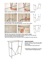
Assembly Step 1
Fix the rear oor bar (2) to base bar (3) using two hexagonal head screws M10x75 (6),
four washers Ø10 (33), two safety nuts M10 (52) and straight retaining plate (7).
Place standpipe (51) onto front oor bar (1) and x it with two hexagonal screws M12x75
(55), four washers Ø12 (54) and two safety nuts (53).
Fix the standpipe (51) to the base bar (3). For this use two hexagonal screws M10x100
(5), four washers Ø10 (33), and two safety nuts M10 (52) and the bent mounting plate
(4).
Assembly - Training Bench
Assembly Step 2
Fix support tube (17) each with two hexagonal head screws M8x20 (19), two washers
Ø8 (32) and distance tube (30) on the rear mount of the sliding carriage (16)
Then place the two guide pipes (20) in the left and right mounts on the base bar (3) and
in the mount on standpipe (17) and x them each with two aluminium caps (21) and two
headless screws M10x16 (56)
/