Page is loading ...

IMPORTANT
TO PREVENT ELECTRICAL SHOCK, POWER SHOULD BE TURNED OFF AT THE FUSE BOX BEFORE INSTALLATION.
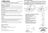
DSK34 - 6” DISK
SAFETY WARNINGS:
Read all product labels and directions.
•
WARNING-Risk of fire or electric shock. Install this kit only in the luminaires that have the construction features and dimensions
shown in the photographs and/or drawings and where the input rating of the retrofit kit does not exceed the input rating of the
luminaire.
•
Do not make or alter any open holes in an enclosure of wiring or electrical components during kit installation.
•
WARNING – To prevent wiring damage or abrasion, do not expose wiring to edges of sheet metal or other sharp objects.
•
Please examine all parts that are not intended to be replaced by the retrofit kit for damage and replace any damaged parts prior
to installation of the retrofit kit.
• Replace only with RAB Lighting Inc. Visit our website: RABLIGHTING.COM Call our experts at 888 722-1000
MODEL# DSK34-6R169XX120WS.
• The recessed luminaire is intended for mounting only in a covered ceiling where only the led side of the luminaire will be
exposed to damp or dry locations.
• INSTALLATION SHOULD ONLY BE PERFORMED AFTER POWER TO THE FIXTURE HAS BEEN DISCONNECTED.
• THIS DEVICE IS NOT INTENDED FOR USE WITH EMERGENCY EXITS.
• These instructions shall be included on an information sheet packaged with each unit.
DSK34-6R169XX120WS
Disk (1) Nuts (3)
DO NOT TO INSTALL OR OPERATE INCANDESCENT LAMPS IN THIS LUMINAIRE
ATT TEMP
THIS LUMINAIRE HAS BEEN MODIFIED TO OPERATE LED LAMPS.
REPLACE ONLY WITH RAB Lighting Inc.
RABLIGHTING.COM 888 722-1000
MODEL#
Lumi Sticker (1)
1
7 3/4”
Bracket(1)
Screws (4)
7
6
5 4
7
6
5
4
THIS SIDE FACING CEILING
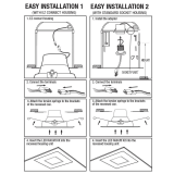
Installation with J-BOX and Existing Housing
A screwdriver is needed for installation.
Compatible with most common 5in and 6in recessed
housings
Female connector(1)
E26 adapter(1)
Screw (2)
Model# DSK34-6/ACC - including E26 adapter, female connector
4”, 5” and 6”
J-box
Min Volume - 15.9 in
3
, Min Length: 3.2in, Height: 1.55in
Compatible with standard J-box
Min lamp compartment dimensions - Dia: 4in, Height: 4.1in

DSK34 - 6” DISK
5. Put the lens back to disk. (Fig.4)
Fig: 1
Fig: 4
Fig: 2
2. Take out lens from disk. (Fig.1)
INSTALLATION WITH J-BOX (Mounting Diameter 2.7 & 3.5in)
1. Make sure the POWER IS TURNED OFF at the source to
the J-box in which you are installing the product.
3. Connect the Ground Wire (Cooper) to J-box and the wires
of J-box to disk, white - white, black - black. (Fig.2)
JBOX
Black (line)
Ground
White (neutral)
Black (line)
Cooper (ground)
White (neutral)
DISK
Nuts
Fig: 3
4. Fasten the disk to J-box with the two short screws provided
in package.
(Fig.3)
(2.7in) (3.5in)
1. Make sure the POWER IS TURNED OFF at the source to the J-box
in which you are installing the product.
Fig: 5
Fig: 6
Fig: 7
2. Take out lens from disk.
(Fig.5)
INSTALLATION WITH J-BOX (Mounting Diameter3.5in)
3. Fasten the bracket to J-box with the two long screws provided
in package. (Fig.6)
7
6
5 4
7
6
5
4
THIS SIDE FACING CEILING
4. Connect the Ground Wire (Cooper) to J-box and the wires of
J-box to disk, white - white, black - black.
(Fig.7)

6. Put the lens back to disk. (Fig.9)
Fig: 9
Fig: 8
5. Fasten the disk to the bracket with the two short screws
provided in package.
(Fig.8)
DSK34 - 6” DISK
7
6
5 4
7
6
5
4
THIS SIDE FACING CEILING
Fig: 13
Fig: 12
4. Install the friction clip on the back of the disk with screws
provided in accessories package.
(Fig.13)
3. Fasten the bracket to J-box with the two short screws
provided in package.
(Fig.12)
7
6
5 4
7
6
5
4
THIS SIDE FACING CEILING
1. Wire the disk with female connector. (Fig.10) Insert the black wire
into the side marked(-) and the white wire into the side without mark.
Make sure both wires are tightly secured.
INSTALLATION WITH 4” EXISTING HOUSING
Fig: 10
Fig: 11
2. Take out lens from disk. (Fig.11)
5. Put the lens back to disk. (Fig.14)
Fig: 14
Fig: 16
Fig: 15
Fig: 17
6. Screw the E26 adapter into the socket. Then connect male
connector of E26 adapter to the female connector of the disk
(Fig.15)
Simply slide the trim and metal friction clips into the housing.
(Fig.16)
ceilings.
(Fig.17)
INSTALLATION WITH J-BOX - Mounting Diameter3.5in (Cont’d) INSTALLATION WITH 4” EXISTING HOUSING (Cont’d)

v
Easy Answers
Fig: 19
Fig: 20
Fig: 21
Fig: 24
Fig: 23
Fig: 22
Fig: 25
INSTALLATION WITH 5”/6” EXISTING HOUSING
2. Make sure the POWER IS TURNED OFF at the source to the
recessed housing in which you are installing the product.
3. Take out lens from disk. (Fig.19)
4. Fasten the bracket to disk with the two short screws provided in
package. (Fig.20) Pay attention to the direction of bracket.
5. Install the torsion springs on the back of the disk. (Fig.21)
Put the lens back to disk. (Fig.22)
DSK34 - 6” DISK
1. Wire the disk with female connector. (Fig.18) Insert the black
wire
into into the side marked(-) and the white wire into the side
without mark.
Make sure both wires are tightly secured.
Fig: 18
7
6
5 4
7
6
5
4
THIS SIDE FACING CEILING
6. Screw the E26 adapter into the socket. Then connect male
connector of E26 adapter to the female connector of the disk
(Fig.23)
Simply slide the trim and
torsion springs
into the
housing.
(Fig.24)
ceilings.
(Fig.25)
INSTALLATION WITH 5”/6” EXISTING HOUSING(Cont’d)
DSK346IN-0820
/