Page is loading ...

R1 Series
Pull-Type Disc Mowers
Driveline Extension Kit (B6390 and B6391)
Installation Instructions
214229 Revision B
Original Instruction
The harvesting specialists.

R1 Series Pull-Type Disc Mower
Published in October 2017

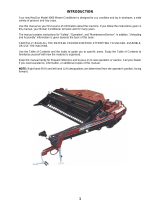
Introduction
Some tractor models using a two-point hitch may require a longer primary driveline than the one shipped from the
factory with MacDon R1 Series Pull-Type Disc Mowers. Driveline Extension kits (MD #B6390 and B6391) can be
used to extend the primary driveline by an additional 152 mm (6 in.) in length. Install the kit that is sized for the
relevant tractor model:
• B6390 – 1-3/8 in. driveline shaft size with 21-tooth spline
• B6391 – 1-3/4 in. driveline shaft size with 20-tooth spline
This document explains how to install the kit. A list of parts included in the kit is provided in Chapter 2 Parts List,
page 5.
Installation Time
Installation time for this kit is approximately 20 minutes.
Conventions
The following conventions are used in this document:
• Right and left are determined from the operator’s position. The front of the mower is the side that faces the crop.
• Unless otherwise noted, use the standard torque values provided in the mower operator’s manual and technical
manual.
NOTE:
Keep your MacDon publications up-to-date. The most current version of this instruction can be downloaded from
our Dealer-only site (https://portal.macdon.com) (login required).
NOTE:
This document is not currently available in any language except English.
214229 i Revision B

List of Revisions
At MacDon, we’re continuously making improvements, and occasionally these improvements affect product
documentation. The following list provides an account of major changes from the previous version of this
document.
Summary of Change
Location
Fixed parts list description. 2 Parts List, page 5
Revised procedure.
3 Installation Instructions, page 7
214229 ii Revision B

214229 iii Revision B
Introduction................................................................................................................................................i
List of Revisions ........................................................................................................................................ii
Chapter 1: Safety .................................................................. .................................................................. 1
1.1 Signal Words ....................................................................................................................................... 1
1.2 General Safety.....................................................................................................................................2
Chapter 2: Parts List .............................................................................................................................. 5
Chapter 3: Installation Instructions ................................................................. .................................. 7
TABLE OF CONTENTS


214229 1 Revision B
1 Safety
1.1 Signal Words
Three signal words, DANGER, WARNING, and CAUTION, are used to alert you to hazardous situations. Signal
words are selected using the following guidelines:
DANGER
Indicates an imminently hazardous situation that, if not avoided, will result in death or serious injury.
WARNING
Indicates a potentially hazardous situation that, if not avoided, could result in death or serious injury.
It may also be used to alert against unsafe practices.
CAUTION
Indicates a potentially hazardous situation that, if not avoided, may result in minor or moderate injury.
It may be used to alert against unsafe practices.

214229 2 Revision B
1.2 General Safety
Figure 1.1: Safety Equipment
CAUTION
The following are general farm safety precautions that
should be part of your operating procedure for all types
of machinery.
Protect yourself.
• When assembling, operating, and servicing machinery,
wear all protective clothing and personal safety devices
that could be necessary for job at hand. Do NOT take
chances. You may need the following:
• Hard hat
• Protective footwear with slip resistant soles
• Protective glasses or goggles
• Heavy gloves
• Wet weather gear
• Respirator or filter mask
Figure 1.2: Safety Equipment
• Be aware that exposure to loud noises can cause hearing
impairment or loss. Wear suitable hearing protection
devices such as earmuffs or earplugs to help protect
against loud noises.
Figure 1.3: Safety Equipment
• Provide a first aid kit for use in case of emergencies.
• Keep a fire extinguisher on the machine. Be sure fire
extinguisher is properly maintained. Be familiar with its
proper use.
• Keep young children away from machinery at all times.
• Be aware that accidents often happen when Operator is
tired or in a hurry. Take time to consider safest way.
Never ignore warning signs of fatigue.
SAFETY

214229 3 Revision B
Figure 1.4: Safety around Equipment
• Wear close-fitting clothing and cover long hair. Never
wear dangling items such as scarves or bracelets.
• Keep all shields in place. NEVER alter or remove safety
equipment. Make sure driveline guards can rotate
independently of shaft and can telescope freely.
• Use only service and repair parts made or approved by
equipment manufacturer. Substituted parts may not meet
strength, design, or safety requirements.
Figure 1.5: Safety around Equipment
• Keep hands, feet, clothing, and hair away from moving
parts. NEVER attempt to clear obstructions or objects
from a machine while engine is running.
• Do NOT modify machine. Unauthorized modifications
may impair machine function and/or safety. It may also
shorten machine’s life.
• To avoid bodily injury or death from unexpected startup of
machine, ALWAYS stop the engine and remove the key
from the ignition before leaving the operator’s seat for
any reason.
Figure 1.6: Safety around Equipment
• Keep service area clean and dry. Wet or oily floors are
slippery. Wet spots can be dangerous when working with
electrical equipment. Be sure all electrical outlets and
tools are properly grounded.
• Keep work area well lit.
• Keep machinery clean. Straw and chaff on a hot engine is
a fire hazard. Do NOT allow oil or grease to accumulate
on service platforms, ladders, or controls. Clean
machines before storage.
• NEVER use gasoline, naphtha, or any volatile material for
cleaning purposes. These materials may be toxic and/or
flammable.
• When storing machinery, cover sharp or extending
components to prevent injury from accidental contact.
SAFETY


214229 5 Revision B
2 Parts List
The following parts are included in the kits.
Figure 2.1: Driveline Half
Kit
Part
Number Description Quantity
B6390 281575 DRIVELINE – 1.375 IN., 21 TOOTH, HALF 1
B6391 281576 DRIVELINE – 1.75 IN., 20 TOOTH, HALF 1


214229 7 Revision B
3 Installation Instructions
CAUTION
To avoid bodily injury or death from unexpected startup of machine, always stop engine and remove key
from ignition before leaving operator’s seat for any reason.
1. Park machine on flat level surface.
2. Lower mower conditioner onto blocks or leave mower conditioner raised.
3. If leaving mower conditioner in raised position, engage lift cylinder lock-out valves.
4. Stop engine, and remove key from ignition.
Figure 3.1: Mower Conditioner
5. Locate primary driveline (A).
Figure 3.2: Primary Driveline
6. Pull back collar (A) on driveline, and slide coupler off
tractor power take-off shaft.
7. Pull out half part of the driveline and store for
future use.

214229 8 Revision B
Figure 3.3: Driveline with Shield On
8. Install the new driveline half (B) (MD #281575 or
MD #281576) to the tractor, as shown.
9. Mark (C) the new driveline shield (B) at end of mower
conditioner’s driveline half (A).
10. Measure and mark a 200 mm (8 in.) overlap (D) from
the mark (C) on the new driveline shield.
11. Remove the driveline shield of the new driveline half (B)
(MD #281575 or MD #281576).
12. Mark (C) tractor’s driveline shaft (B) at end of mower
conditioner’s driveline half (A).
13. Measure and mark a 150 mm (6 in.) overlap (D) from
the mark (C) on the tractor’s driveline shield.
14. Cut the tractor’s driveline shaft and shield at the
overlap marks.
Figure 3.4: Uncut Driveline
15. If you have cut more than 26 mm (1 in.) off the end of
the new driveline half, you will need to relocate the
grease fitting (A). Cut a 26 mm (1 in.) access hole (B) in
the driveline’s outer shield.
16. Through the access hole, drill/tap a hole in the shaft,
26 mm (1 in.) back from the newly cut end of the shaft,
and move the grease fitting (A) there.
Figure 3.5: Primary Driveline
17. Connect the trimmed driveline half (A) to the existing
driveline half, then position to storage hook (B) or
connect to tractor power take-off (PTO).
INSTALLATION INSTRUCTIONS


MacDon Industries Ltd.
680 Moray Street
Winnipeg, Manitoba
Canada R3J 3S3
t. (204) 885-5590
f. (204) 832-7749
MacDon, Inc.
10708 N. Pomona Avenue
Kansas City, Missouri
United States 64153-1924
t. (816) 891-7313
f. (816) 891-7323
MacDon Australia Pty. Ltd.
A.C.N. 079 393 721
P.O. Box 243, Suite 3, 143 Main Street
Greensborough, Victoria, Australia 3088
t. 03 9432 9982
f. 03 9432 9972
MacDon Brasil Agribusiness Ltda.
Rua Grã Nicco, 113, sala 202, B. 02
Mossunguê, Curitiba, Paraná
CEP 81200-200 Brasil
t. +55 (41) 2101-1713
f. +55 (41) 2101-1699
LLC MacDon Russia Ltd.
123317 Moscow, Russia
10 Presnenskaya nab, Block C
Floor 5, Office No. 534, Regus Business Centre
t. +7 495 775 6971
f. +7 495 967 7600
CUSTOMERS
MacDon.com
DEALERS
Portal.MacDon.com
Trademarks of products are the marks of their
respective manufacturers and/or distributors.
Printed in Canada
/